Page is loading ...

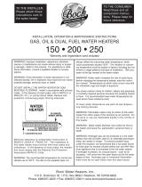
Commercial/Industrial
Water Heaters
3-Year Limited Warranty
Featuring Bock’s Legendary
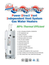
Multiple heat exchangers
inside each unit with
hundreds of turbons to
boost heat transfer --
heating water faster
with less fuel.
166 to 275 Gallon Capacities
400,000 to 1,500,000 BTU
Wet Leg Design - Combustion
chamber is surrounded by water on
all sides for continuous operation and
additional heat transfer
Cobalt-enriched Glass-Lined Tank
Multiple Magnesium Anode Rods
(from 4 to 11 by model)
to Inhibit Corrosion
Integrated 2” Steel Skid for Safe
and Easy Movement
Large Handhole Cleanouts are standard
Power Gas, Oil and Dual Fuel Burners
ASME construction is available
Multi-Flue

www.bockwaterheaters.com
110 South Dickinson Street , Madison, Wisconsin 53703
Toll Free 800.794.2491
•
Phone 608.257.2225
●
Fax 608.257.5304
80015 Rev 2/08
*Nipple not included
**Weight includes burner and controls
NOTE: To specify burner type use “E” for oil, “G” for power gas, and “DF” for dual fuel
T&P Valve: Factory Installed
Drain Valve: Factory Installed Brass Valve
Standard Voltage (all): 120V, 60 Hz, 1P
Pressures (all): Working Pressure, 150 psi; Testing Pressure, 300 psi
Burner Motor does not exceed .75HP
ASHRAE: All Bock Products Meet or Exceed Current ASHRAE Standards.
Warning: Do not install on combustible ooring. Installation should be in accordance with all national and/or local codes. In the absence of local
codes, refer to NFPA 31, NFPA 54 or ANSI Z.21.10.1.
Caution: The recommended maximum hot water termperature setting for normal residential use is 120°F. Bock recommends a tempering valve or
anti-scald valve be installed and used according to the manufacturer’s directions to prevent scalding.
FRONT SIDE
E
H
G
F
D
C
B
A
AQUASTAT
RETURN*
OUTLET*
HIGH LIMIT
OBSERVATION
DOOR
T&P
RELIEF
VALVES
INLET*
Multi-Flue
(on selected models)
Model
Storage
(gal)
Rated Input
Recovery
@ ∆ 100°F
(GPH)
Oil/Dual
Fuel
Recovery
Time @
∆ 100°F
(GPH)
Oil/
Dual Fuel
Recovery
@ ∆ 100°F
(GPH)
Power
Gas
Recovery
Time @
∆ 100°F
(GPH)
Power
Gas
Inlet
Pipe
Dia.
Outlet
Pipe
Dia.
Return
Pipe
Dia.
Dimensions
Shipping Weight
(lbs)**
BTH/HR GPH A B C D E F
G
Oil
G
Power
Gas
G
Dual
Fuel
H Standard ASME
150-400 175 400,000 2.8 402 26 393 27 2” 2” 2” 76” 67” 8” 40” 8” 18” 12” 19-3/4” 29-1/2” 40” 2,108 2,283
150-600 166 600,000 4.3 604 17 589 17 2” 2” 2” 76” 67” 8” 40” 8” 18” 12” 19-3/4” 29-1/2” 40” 2,208 2,383
150-800 157 800,000 5.7 805 12 785 12 2” 2” 2” 76” 67” 8” 40” 10” 18” 12” 19-3/4” 29-1/2” 40” 2,308 2,483
200-450 245 450,000 3.2 453 29 442 30 2” 2” 2” 79” 69” 8” 42” 8” 19” 12” 19-3/4” 29-1/2” 44” 2,665 2,840
200-650 212 650,000 4.6 654 19 638 20 2” 2” 2” 79” 69” 8” 42” 8” 19” 12” 19-3/4” 29-1/2” 44” 2,735 2,910
200-850 204 850,000 6.1 855 14 835 15 2” 2” 2” 79” 69” 8” 42” 10” 19” 12” 19-3/4” 29-1/2” 44” 2,815 2,990
200-1150 191 1,150,000 8.2 1157 10 1129 10 2” 2” 2” 79” 69” 8” 42” 12” 19” 14” 19-3/4” 29-1/2” 44” 2,925 3,100
250-800 271 800,000 5.7 808 20 785 21 2” 2” 2” 86” 76” 8” 40” 10” 19” 12” 19-3/4” 29-1/2” 48” 3,516 3,700
250-1000 257 1,000,000 7.1 1017 15 982 16 2” 2” 2” 86” 76” 8” 40” 12” 19” 14” 19-3/4” 29-1/2” 48” 3,606 3,954
250-1250 247 1,250,000 9.0 1253 12 1227 12 2” 2” 2” 86” 76” 8” 40” 14” 19” 14” 19-3/4” 29-1/2” 48” 3,666 3,999
250-1500 247 1,500,000 11.0 1527 10 1473 10 2” 2” 2” 86” 76” 8” 40” 14” 19” 33-3/4” 33-3/4” 33-3/4” 48” 3,726 4,560
/


