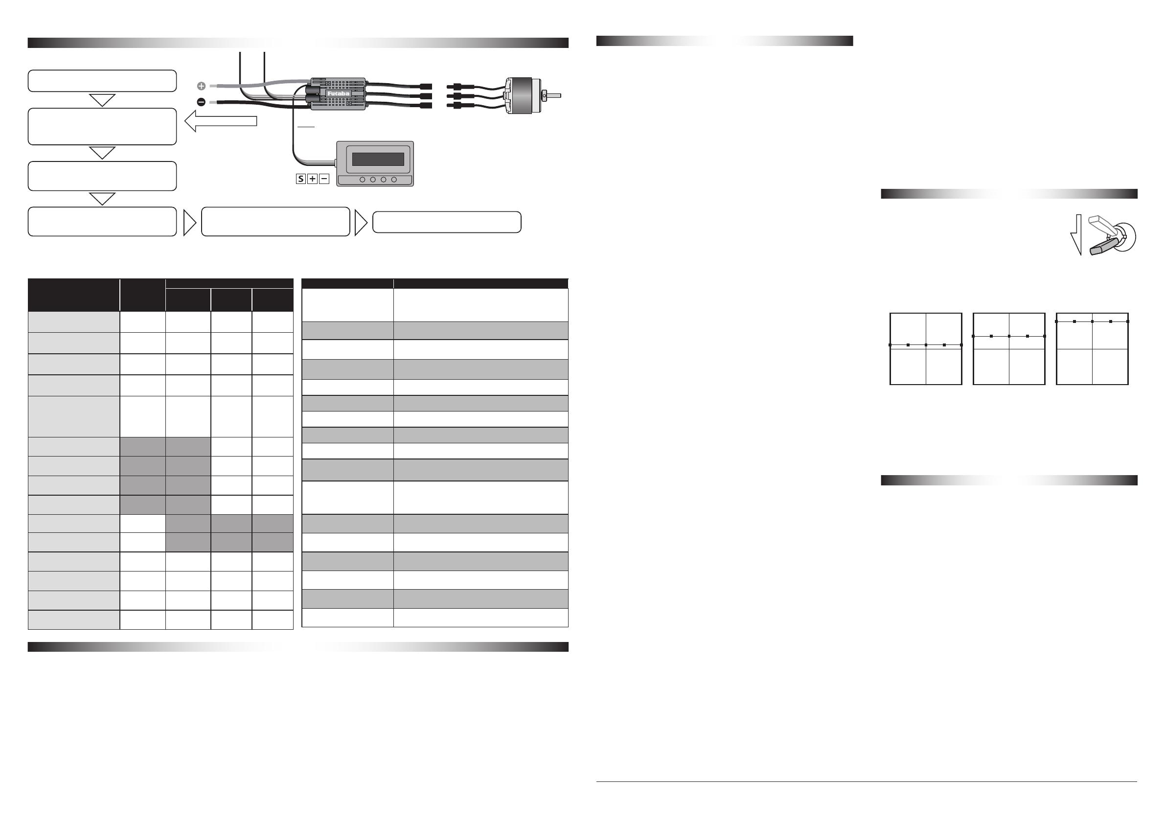
ESC Programming
MC-980H/A
To drive battery Program wire
White Red Black Program box MCP-2(Sold separately)
Connect the program box MCP-2 and
the battery to the ESC as shown.
1
After changing the parameter values,
press the "OK" button to save the new
values you entered in the ESC.
4
Press any button.
Connecting ESC → Please Wait.
→ SoftwareVer → 1: Flight Mode
2
Press the "ITEM" button to browse
for other programmable items or exit
programming.
5
Press the "ITEM" button to browse the
programmable items. Press the "VALUE"
button to change the parameter value.
3
Disconnect the battery and programming
cable from the ESC and program box.
6
RPM standardization(When using a helicopter governor )
Program items 〇: Default
ITEM Setting items
1. Flight Mode
● Fixed-wing Air plane
● Ext.Gov Heli linear
〇 Heli ElfGov Elf Governor
● Heli StoGov Store Governor
2. LiPo Cells 〇 Auto Calc
● 3-6 cells
3. Cuto Type 〇 Soft Cuto
● Hard Cuto
4. Cuto Volt ● Disabled
● 2.8 V~3.8 V ( 〇 Default 3.0 V)
5. BEC Voltage ● 5 V~8 V ( 〇 Default 6.0V)
6. Start-up Time ● 0~21 ( 〇 Default 11)
7. Gov Param P ● 0~9 ( 〇 Default 4)
8. Gov Param I ● 0~9 ( 〇 Default 5)
9. AR time
Autorotation restart time ● 0 s~90 s ( 〇 Default 25 s)
10. Restart Accel
Restart acceleration time ● 1 s~3 s ( 〇 Default 1.5 s)
11. Brake Type
〇 Disabled
● Normal
● Proportiona
● Reverse
12. Brake Force ● 0~100% ( 〇 Default 0%)
13. Timing ● 0° ~30° ( 〇 Default 15° )
14. Motor Rotate 〇 CW
● CCW
15. Active FW
Regenerative brake 〇 Enabled
● Disabled
16. Startup Power ● 1~7 (〇 Default 3)
17. Restore Default Press OK to reset to Default.
Flight Mode Air plane
Helicopter
Linear
Throttle
Elf
Governor
Store
Governor
LiPo Cells Adjustable Adjustable Adjustable Adjustable
Cuto Type Adjustable Adjustable Adjustable Adjustable
Cuto Volt Adjustable Adjustable Adjustable Adjustable
BEC Voltage Adjustable Adjustable Adjustable Adjustable
Start-up Time Adjustable
Adjustable
when soft
start is
enabled /
disabled
Adjustable Adjustable
Gov Param P ― ― Adjustable Adjustable
Gov Param I ― ― Adjustable Adjustable
AR time
Autorotation restart time ― ― Adjustable Adjustable
Restart Accel
Restart acceleration time ― ― Adjustable Adjustable
Brake Type Adjustable ― ― ―
Brake Force Adjustable ― ― ―
Timing Adjustable Adjustable Adjustable Adjustable
Motor Rotate Adjustable Adjustable Adjustable Adjustable
Active FW
Regenerative brake Adjustable Adjustable Valid
(Not adjustable)
Valid
(Not adjustable)
Startup Power Adjustable Adjustable Adjustable Adjustable
ESC has four flight modes. See the table below to see what
is programmable in each mode.
1. Theory of RPM Standardization
During the RPM standardization, the ESC will establish a “Motor RPM-Throttle” curve
by itself based on the actual battery voltage and the actual KV rating of the motor.
Therefore, you need to standardize the speed with a fully charged battery, and
ensure the main blade pitch is 0° (in order to make the helicopter not take off). In
general, people use the default “Throttle Curve & Pitch Curve” of the transmitter (as
shown below) when they standardize the speed.
Attention! Please ensure the main blade pitch is 0° and the throttle amount is
above 40% (we recommend using 50%) when standardizing the speed.
2. Procedures of RPM Standardization
• We recommend using the default “Throttle Curve & Pitch Curve” . (If you don’ t
want to use the default setting, then please ensure the throttle amount is 50%and
the main blade pitch is 0° when the motor rotates.
• Turn on the transmitter, move the throttle stick to the bottom position and then
wait for the ESC completing the self detection.
• If you’ ve set the “throttle cut” function, please lock the “throttle cut” , and then
move the throttle stick to the 50% position and then unlock the “throttle cut” . If
there is no “throttle cut” , then you can move the throttle stick to the 50% posi-
tion directly.
• The ESC drives the motor to rotate, the main blades start to accelerate slowly (be-
cause the main blade pitch is 0° , so the helicopter won’ t take off, but you still
needs to be careful), you need to wait for the acceleration completing and the
speed getting stable, and then lock the “throttle cut” or move the throttle stick to
the bottom position.
• The ESC will stop driving the motor, the main blades start to slow down and then
stop rotating.
• he RPM standardization completes.
Attention! Please calibrate the throttle range before the RPM standardization. There
will be no need if you’ ve carried out the ESC/Radio Calibration when the first time
you used this ESC or you didn’ t restore the settings to factory defaults after the
calibration (changing the transmitter & receiver is an exception).
Transmitter settings
Throttle Cut settings
Throttle curve setting
Program items
Each protection function
1. Flight Mode
1-1 Fixed-wing
In “Fixed-wing” mode, the motor will start up when the throttle amount reaches 5%
or above. There is no soft start-up, the motor responds to the throttle increase rapidly.
1-2 Helicopter Linear Throttle
In “Helicopter (Linear Throttle)” mode, the motor will start up when the throttle
amount reaches 5% and it will start up in a soft way with the throttle (from 0 to 100%)
acceleration time is fixed to 3.5 seconds. It will accelerate to the RPM corresponds to
the specific throttle amount at the fixed rate.
1-3 Helicopter Elf Governor
In “Helicopter (Elf Governor)” mode, the motor will start up when the throttle amount
reaches 40% or above. And it will complete the speed standardization and enter the
speed-governing operation in the preset start-up time. In this mode, the motor will
standardize its speed every time it starts up. Due to dierent discharge rates/capabili-
ties of dierent batteries, the RPM you standardize each time may be a little dierent.
In consequence, at the same throttle amount, the RPM may be a bit dierent when
using dierent batteries, but this won’ t aect the speed-governing eect.
1-4 Helicopter Store Governor
In “Helicopter (Store Governor)” mode, the motor will start up when the throttle
amount reaches 40% or above. It will also start up in a very soft way. And it will also
complete the speed standardization and enter the speed-governing operation in
the preset start-up time. In this mode, the motor will only standardize its speed
the rst time when it starts up. When performing RPM standardization for the rst
time, we recommend using a fully-charged battery with good discharge capability.
After the RPM standardization, change another battery to y your aircraft. At the
same throttle amount, the RPM should be the same as the RPM of the rst ight. For
consistent control feel, we recommend using this mode.
2. LiPo Cells
The ESC will automatically calculate the number of LiPo cells you have plugged in as
per the “3.7V/Cell” rule if “Auto Calc.” is selected. Or user can set this item manually.
3. Cuto Type
The ESC will gradually reduce the output to 50% of the full power in 3 seconds after
the voltage cuto protection is activated, if soft mode is selected. It will immediately
cut o all the output when hard mode is selected.
4. Cuto Volt
2.8 V-3.8 V (custom), 3.0 V (default).
5. BEC Voltage BEC
5-8 V (adjustable), 0.1V (step), 6 V (default).
6. Start-up Time
0-21(adjustable), 11 (default). Note: It only functions in Helicopter Store Governor
and Helicopter Elf Governor.
7. Gov Param P
Governor correction response proportional control adjustment. Increasing the value
will improve the correction response. The correction when the rotation drops is faster,
but the rotation speed becomes easier to hunting. In that case, lower the value.
8. Gov Param I
Governor correction response Integral control adjustment. Use this when you want to
make further adjustments by adjusting the governor parameter p. Increasing the value
will improve the correction response, but the number of revolutions will hunting. In that
case, lower the value.
9. AR time Autorotation restart time
This is a function only for the governor. Throttle works in the range of 5% to 40%. The
motor can be restarted quickly when the autorotation descent is interrupted. If you
set the value to 10 seconds and want to instantly cancel the autorotation descent,
turn o the HOLD switch and increase the throttle to 40%, and the motor will rotate
immediately. (It will reach full power from rest in 1.5 seconds.) If the Throttle HOLD
switch is turned on for 10 seconds or longer, this function will not work.
● If the autorotation landing is successful within 10 seconds, never turn o the hold
switch before out of battery. If the hold switch is turned o, there is a danger that
the motor will rotate at full speed in 1.5 seconds, which may cause an accident.
For example, if the IDLE-UP switch is ON and the HOLD switch is turned OFF after
landing, the blades of the main rotor will rotate at high speed, and there is a
danger that the helicopter will suddenly surface or tip over.
● If this function is not used in governor mode, the motor will only start slowly
even if the hold switch is turned o.
10. Restart Accel
1-3s (adjustable), 0.5s (step), 1.5s (default). This item controls the time the motor
will cost to restart and accelerate to the full speed. (This function only eects in
“Helicopter Governor Elf/Store” mode)
11. Brake Type
Proportional Brake:when the throttle range on the transmitter is between 20%
and 100%, the corresponding ESC throttle output is between 0% and 100%.When
the throttle range on the transmitter is between 20% and 0%, the corresponding
brake force is between 0 and 100%
Reverse:Set the reverse switch (ON-OFF) on the transmitter. When the Reverse
line is connected to that channel and the amount of operation exceeds 20%, the
reverse function is activated. When the power of ESC is started, ESC will not start
unless the reverse switch is OFF. When the reverse switch is turned on, the throttle
stick is raised and the motor reverses linearly.
12. Brake Force
0-100% (adjustable), 1% (step), 0 (default).
Note: this function only effects in “Normal Brake” mode.
When using the governor with ESC, set the throttle cut
function on the transmitter. Set the Throttle to be fixed in the
stopped state when the throttle cut switch is turned on. Be
sure to perform connect the battery in the state of throttle
cut. When the throttle cut switch is turned off, the motor
starts (it starts to rotate slowly to the specified number of
revolutions) and is ready for flight. After landing, throttle cut to stop the motor.
13. Timing
0-30° (adjustable), 1° (step), 15° (default).
14. Motor Rotate
CW/CCW. User can adjust this item via a program box.
15. Active FW Regenerative brake
It can be set in "Air plane" mode or "Helicopter: Linear Throttle" mode. It cannot
be set in store governor and ELF governor modes. When the propeller is in free
rotation, such as during diving, the generated power from the motor is regenerated
to charge the battery. At the same time, the effect of braking the aircraft will occur.
16. Startup Power
This item is for adjusting the start-up force of the motor (during the start-up
process). The higher the value, the larger the start-up force. It’s adjustable between
1 and 7 (and it’s 3 by default).
17. Restore Default
Press OK to reset to Default.
1. Start-up Protection
The ESC will monitor the motor speed (RPM) during the start-up process. When the speed stops
increasing or the speed increase is not stable, the ESC will take it as a start-up failure. At that time,
if the throttle amount is less than 15%, then the ESC will automatically try to restart up; if it is
larger than 20%, then you need to move the throttle stick back to the bottom position and then
restart up the ESC.
(Possible causes of this problem: poor connection/ disconnection between the ESC and motor
wires, propellers are blocked, etc.)
2. ESC Thermal Protection
The ESC will gradually reduce the output but won’ t cut it off completely when the ESC
temperature goes above 110 . For ensuring the motor can still get some power and won’ t cause
crashes, so the maximum reduction is about 50% of the full power. The ESC will gradually resume
its maximum power after the temperature lowers down. In addition, the ESC temperature cannot
exceed 70 when it’ s powered on. Otherwise, it cannot be started up but flashes Blue LED and
beeps a series of beeps to indicate the ESC temperature is too high. (Here we are describing the
ESC’ s reaction in the “Soft Cutoff” mode, while if in the “Hard Cutoff” mode; it will immediately
cut off the power.)
3. Thermal protection of capacitors
The ESC activates this protection when the operating temperature of the capacitor exceeds 130 °C.
This protects the capacitor in the same way that ESC thermal protection does for ESC.
4. Throttle Signal Loss Protection
When the ESC detects loss of signal for over 0.25 second, it will cut off the output immediately
to avoid an even greater loss which may be caused by the continuous high-speed rotation of
propeller. The ESC will resume the corresponding output after normal signals are received.
5. Overload Protection
The ESC will cut off the power/output and automatically restart itself when the load suddenly
increases to a very high value. If the load still remains high or the motor still remains out of sync,
then it will completely cut off the power/output.
6. Over-current Protection
During use, the ESC will cut off the output immediately if the current exceeds the regulated value
and then resume it quickly; the ESC will cut off the output completely and won’ t resume it if the
regulated value is exceeded again.
In governor mode, set the throttle curve to a horizontal straight line. Set the value
according to the rotor speed.
EX : ● Normal : 55% ● Idle-up1 : 70% ● Idle-up 2 : 80%
Be sure to connect the battery with Throttle Cut ON.
When Throttle Cut is turned o, the motor starts and starts waiting.
After landing, turn on Throttle Cut to stop the motor.
Normal curve Idle-up 1 Idle-up2
●Throttle curve setting
Throttle Cut
FUTABA CORPORATION
Hobby Radio Control Business Center Sales & Marketing Department 1080 Yabutsuka, Chosei-mura, Chosei-gun, Chiba-ken, 299-4395, Japan TEL: +81-475-32-6051, FAX: +81-475-32-2915
©FUTABA CORPORATION 2021, 11 (1)


