Newel 3

DIGITEL Newel 3 User manual

  • Hello! I've reviewed the user manual for the N43 Energy Meter. This document provides details on how to configure the meter, connect it to communication buses, and how to use it to measure network parameters and analyze energy consumption. It also covers the usage of an impulse counter. I'm ready to assist with any questions you may have about the device described in this document.
  • What communication parameters must be set for the N43 counter?
    What is the minimum impulse length for the impulse counter?
    What parameters of the network are measured by N43 Energy Meter?
127
USER MANUAL
ENERGY METERING
Digitel reserves the right to modify the
technical characteristics described
without prior notice.
Non-contractual document
Digitel SA
All rights reserved
128
11. ENERGY METERING
11.1. ENERGY COUNTER N43
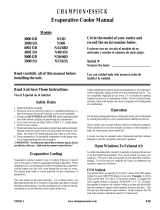
Energy metering can be performed using the N43 meters. They must be connected to one of the
communication buses according to the diagram below. They measure all important parameters of the network.
These values, recorded in the central unit, allow a detailed analysis of the consumption, creation of statistics,
estimation of the operating costs etc ...
The communication parameters of the N43 counter must be programmed as follows:
[Adr] - 1 à 31 (address - value between 1 and 31 unique for each module)
[trb] - r8n1
[bAU] - 19.2k
L1
L2
L3
N
S1
S1
S1
S2
S2
S2
P1
P1
P1
P2
P2
P2
AL1 AL2 AL3Uaux
~RS485
A
B
GNDI OC +
DC58
25 24 18
19
20
21
22
23 17 16 15 9
10
11
12
13
14 87
4
3
156
N43 DIGITEL
13 1514 16 17 18 19 20 21 22 23 24 25
1 32 4 5 6 7 8 9 11
N43 DIGITEL
13 1514 16 17 18 19 20 21 22 23 24 25
1 32 4 5 6 7 8 9 11
N43 DIGITEL
13 1514 16 17 18 19 20 21 22 23 24 25
1 32 4 5 6 7 8 9 11
BUS 1
BUS 2
BUS 3
2
129
11.2. IMPULSE COUNTER
The diagram below shows the measurement of energy consumption using a pulse counter.
Figure 11.1.1
Figure 11.1.2
Impulse outpout
Impulse length
min. 50ms
Max. 10 meters
L1 L3L2
Impulse outpout
Impulse length
min. 50ms
Max. 10 meters L1 L3L2
Energy counter N°1
Energy counter N°2
-
+
-
+
BUS
N
L1
N
Alarm
Output
RL3
Output
RL2
Output
RL1
C3 C4 C5
The contact between 26 and
28 will be interrupted in case
of an alarm or interruption in
supply
DC24D
31 30 29 28 27 26 25 24 23 22 21 20
1 2 3 4 5 6 7 8 9 10 11 12 13 14 15
40 41 42 43 44 45 46
130
/