Page is loading ...

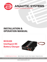
INSTALLATION &
OPERATION MANUAL
8128 River Way, Delta B.C. V4G 1K5 Canada T. 604.946.9981 F. 604.946.9983 TF. 800.668.3884 (US/CANADA)
www.analyticsystems.com
An ISO9001 Registered Company Battery Chargers • Inverters • Power Supplies • Voltage Converters
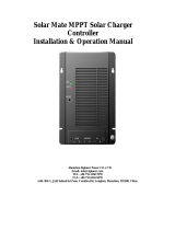
SMP100
MPPT SolarMax
Charge Controller

Copyright (2005-2020) Analytic Systems Ware (1993) Ltd.
Revised - March 25, 2020

3
SAVE THESE INSTRUCTIONS — This manual contains important safety and operating instructions for the charge
controller
WARNING
Installation of the SolarMax Charge Controller should be performed by qualied personnel only. The SolarMax has no
user-serviceable parts. To reduce the risk of electric shock, do not perform any installation (or servicing) other than
specied in these instructions. See our RMA and warranty policies should servicing be required.
1. Do not expose the SolarMax charge controller to rain, snow, spray, or dust. To prevent overheating, do not
obstruct any ventilation openings.
2. Use of an attachment not recommended or sold by Analytic Systems may result in a risk of re, electric shock,
or injury to persons.
3. Do not disassemble the SolarMax charge controller; consult the manufacturer rst, or take it to a qualied
serviceman when service or repair is required. Incorrect reassembly may result in a risk of electric shock or re.
4. To reduce risk of electric shock, disconnect from solar panel before attempting any maintenance or cleaning.
5. Never place the SolarMax charge controller directly above a battery; gases from battery will corrode and
damage it.
6. Never allow battery acid to drip on the SolarMax charge controller, especially when checking the specic
gravity of the battery or lling battery with distilled water.
Always isolate the SolarMax charge controller. Connect and disconnect the DC output connections only after
disconnecting the solar panels from the SolarMax charge controller.
CHARGE CONTOLLER
IMPORTANT SAFETY INSTRUCTIONS

4
Overview of SolarMax MPPT Charge Controller
Introduction
Congratulations on choosing a photovoltaic electric system for your energy storage needs. When properly planned and
installed, your system will give you decades of trouble-free service.
The Analytic Systems SMP100 SolarMax MPPT Charge Controller is a key component of your system. SolarMax accepts
a wide range of input voltages from 30-230 volts, and support a similarly wide range of battery voltages from 24 to 72
Volts nominal (battery voltage must be equal to or less than solar panel voltage). SolarMax features a patented MPPT
(Maximum Power Point Tracking) algorithm allowing you to maximize the energy harvested from your solar array.
SolarMax allows you to use a higher voltage PV array than the batteries you are charging as it is designed to step down
the array voltage, allowing greater exibility in the choice of array for your system.
A PC communications port and software allow viewing and programming SolarMax parameters as well as data logging.
A battery temperature sensor (supplied) allows programmable compensation of the charging voltage.
How the charger operates
The SolarMax is a DC-to-DC smart battery charger that works in two ways. The charger harvests the maximum energy
from the PV (Photo-Voltaic) array using Analytic Systems’ patented maximum power point tracking (MPPT) strategy. The
controller’s secondary objective is to ensure that the batteries receive a full charge without becoming overcharged. This
is accomplished through a three stage charging process. The end result is that you can safely maintain your energy
storage system while getting the maximum benet of your solar array.
The DC to DC converter feature of the SolarMax allows for a wide variety of PV array inputs and battery voltage
congurations. Batteries may be congured from 24 to 72 volts nominal. PV arrays may be wired up to maximum
allowable Voc (Open Circuit Voltage) of 230 volts at worse case conditions.
Chargeable battery types
This charger is designed to charge both starting and deep cycle lead acid batteries and all versions of these batteries:
• Wet Cell (ooded)
• Gel Cell
• Absorbed Glass Mat (AGM).
See your battery manufacturers’ documentation for recommendations for bulk absorption and oat voltage levels.
Support for Lithium-Ion and other battery types will be provided by future rmware updates.
For example, a Mitsubishi PV-MLE270HD module has an Open Circuit Voltage of 38.4 volts at 25C, but at -25C, the Voc
rises to 120% or 46.08 volts. Dividing 230 by 46.08 gives a result of 5, so 5 of these panels can be wired in Series for
1350 watts per string, and then as many strings in parallel as will produce the maximum output power at the nominal
battery voltage as shown in the table below.
The charging of batteries from a solar array is enhanced by the use of a patented MPPT control design as explained in
detail below.

5
Maximum Power Point Tracker
MPPT Power from the PV array (green) and the Current vs. Voltage (blue)
MPPT Maximum Power Point Tracking
MPPT enables the SolarMax Charge Controller to utilize the maximum power available from the PV array. A solar panel
has a variable power output. Power is measured in watts and is the product of the voltage multiplied by the current.
The SolarMax constantly searches for this maximum power point, using a patented MPPT algorithm, to ensure that you
get the maximum
Charge Controller
A maximum power point tracker (or MPPT) is a high efciency DC to DC converter which functions as an optimal
electrical load for a solar array, and converts the power to a voltage and current level which is optimum for charging
batteries.
The benets of MPPT regulators are greatest during cold weather, on cloudy or hazy days or when the battery is deeply
discharged. The SolarMax Charge Controller also monitors battery voltage and temperature to prevent overcharging.
The Charge Controller can accept PV open cell voltages (Voc) up to 230 volts for charging lead acid batteries. SolarMax
produces up to 100 amps of charging current for battery voltages between 24 and 72 volts.
When charging, the SolarMax regulates the voltage and output current to the battery, based on the amount of power
available from the PV array, the state of charge of the battery and the temperature of the battery bank.

6
Charging Lead Acid Batteries
For standard ooded lead acid batteries, vent caps should always be kept in place and tight during both charging and
discharging.
It is very important to monitor the water level in the batteries (if possible). Rell the batteries as necessary using
distilled water. If the batteries need water frequently, recheck the charging voltage settings of the SolarMax and
reduce if necessary.
Three Stage Battery Charging
The three stage charging process results in a more efcient charging of the batteries. The three stages of charging are
the bulk stage, the absorption stage and the oat stage. Your SolarMax Charge Controller will automatically move from
one charging stage to the next as your batteries require.
Bulk Stage
In this rst stage of the charging, the battery is allowed to have a large constant draw on the available current.
SolarMax uses MPPT technology to provide the maximum available power in this stage, to shorten the charge
time or increase the amount of stored energy.
Absorption Stage
The absorption stage commences when the charging voltage reaches the preset absorption voltage. SolarMax
continues to charge at this constant elevated voltage until the current reaches the switch to oat preset.
Absorption charging applies peak charge until battery is fully charged. This stage is critical to using the storage
capacity of the batteries to their full potential.
Float Stage
The Float stage is a maintenance charge at a preset constant voltage. It can be maintained indenitely to ensure
the batteries maintain the maximum state of charge by allowing the current to vary.

7
Charge Timer
The charge timer starts once battery voltage goes above the oat voltage by a certain amount. The timer will run for
a pre-determined amount of time based on the battery specications provided by the manufacturer, but is adjustable
in the PowerWizard software. When the timer expires, the charger will switch into oat mode. A new timer will start
and the charger will not return to bulk or absorption mode for a predetermined amount of time to allow the battery to
recover.
Battery Maintenance
Maintain the batteries in your battery storage system according to the battery manufacturer’s recommendations. In
particular, monitor the water level in the batteries as described on the previous page.
Battery Temperature Sensor
A Battery Temperature Sensor (BTS) is included with the SolarMax charge controller. Battery temperature affects
the ideal charging voltage, the cooler the battery temperature the higher the ideal charging voltage. SolarMax, with
a properly installed BTS, will protect the batteries from overcharging by adjusting the charging voltage to match the
battery temperature. One of the setup values in PowerWizard is the Battery Temperature Coefcient. This value should
be supplied by the battery manufacturer and used during setup. There is no need to use a minus sign when entering the
coefcient. The coefcient is the value recommended by the manufacturer times the number of batteries in series.
The BTS should be rmly attached to a battery in a central part of the pack by double sided tape, either on the side or
on the top of the battery

8
System Calculations
Loads
The rst step in planning a PV system is to determine the load. What is the power intended for? How much power will
be required and for how long? There are many resources available in print and on-line to help determine average and
peak load requirements. It is recommended that you use these resources to calculate anticipated load requirements
and that your system planner design for load growth. Experience has shown that loads rarely remain static over time,
and most often increase. Once the load characteristics are determined your system planner can make decisions about
the appropriate battery voltage, and hence the number and arrangement of batteries that can meet the anticipated
demands. This leads to the charging current and voltage needed from the SolarMax to charge the batteries.
Maximum Voc
The maximum operating input voltage of the SolarMax is 230 volts. Above this voltage the unit will shut down to avoid
damage. The absolute maximum input voltage the controller can accept without damage is 250 volts. In practice the
actual voltage should never reach the Voc point as SolarMax will be loading the array down to the Maximum Power
Point at all times unless the batteries reach full charge and will not accept any more charge current.
Conversion Efciency
The conversion efciency of the SolarMax in the proposed conguration must be considered. The table below
shows the minimum Vmp and recommended Vmp (Maximum Power Voltage) for each battery voltage as well as
the recommended array power. Also keep in mind not to exceed the maximum open circuit voltage in any array
conguration.
Nominal
Battery
Volts
Battery
Float Volts
Battery
Absorption
Volts
Maximum
Output Power
(Watts)
Recommended
Array Power (Watts)
Minimum Maximum
Power Voltage
(Vmp)
Recommended
Maximum Power
Voltage (Vmp)
Maximum Open
Circuit Voltage
(Voc)
24 27.2 28.8 2880 3000 30 Volts 55 Volts 230 Volts
28 31.7 33.6 3360 3500 35 Volts 62 Volts 230 Volts
36 40.8 43.2 4320 4500 45 Volts 80 Volts 230 Volts
48 54.4 57.6 5760 6000 60 Volts 106 Volts 230 Volts
60 68.0 72.0 7200 7500 75 Volts 133 Volts 230 Volts
72 81.6 86.4 8640 9000 90 Volts 160 Volts 230 Volts

9
Every brand of panel is different, so ensure you are familiar with your panels’ specications. Also be aware that
weather and temperature will affect the Voc of your panels. A higher temperature will produce a lower Voc and lower
Vmp voltage, while lower temperatures will produce a higher Voc and higher Vmp voltage. To determine the corrected
Voc, consult the data sheet for your solar panel and allow for the lowest possible temperature the solar panel will
be exposed to. If the data sheet is not available, use the table below to make the calculation using the formula Voc
Expected = Voc @ 25C * Correction Factor.
Temperature Correction Factor
25° to 10° C (77° to 50° F) 1.06
9° to 0° C (49° to 32° F) 1.10
-1° to -10° C (31° to 14° F) 1.13
-11° to -20° C (13° to -4° F) 1.17
-21° to -40° C (-5° to -40° F) 1.25
Wire Sizing
The distance between the PV array and the controller will be a factor in choosing an optimum string voltage for the
SolarMax. The higher the input voltage the smaller the wire can be for any given amount of power. Be sure to consult
your local electrical code specications regarding wire sizing.
SolarMax is designed to deliver a maximum of 100 amps to the output. The wire size chosen must be rated for this
much current over the length of the run between SolarMax and the batteries. The NEC requires that the output
conductors have an amperage capacity of 1.25 X the rated current after all temperature and conduit ll corrections are
calculated. For the SolarMax this means conductors must be rated to carry 125 amps. The minimum cable necessary
to carry the full rated output of the SolarMax is #2 AWG, corrections for cable run length, conduit ll and temperature
could result in a larger wire size being necessary, to a maximum of #1/0 AWG.
The maximum input current is a function of the array Short Circuit Current (Isc), assuming a failure of SolarMax that
creates a short circuit on the input. In this case, multiply the Isc rating of one panel times the number of panels in
PARALLEL to determine the maximum short circuit current.
PV input circuits require a double correction factor for over current so PV Isc (short circuit current) must be multiplied
by 1.56. All PV input wires must be sized accordingly. This apparent over sizing is done to reect the fact that solar
modules can, and often do, produce more than their rated power in conditions of heightened insolation and cold
temperatures. Any PV input disconnect or circuit breaker must also be rated at 1.56 of array Isc.
Coming back to our example solar panel, the Mitsubishi PV-MLE270HD, the Isc for one panel is 9.18 amps, and from
the charts we can see that there is almost no temperature coefcient. Assuming 5 panels in series for 1350 watts per
string, and 7 strings for a maximum power of 9450 watts, the maximum short circuit current would be 9.18 x 7 or 64.26
amps. Multiplying this times the safety factor of 1.56 gives a maximum of 100 amps, so likely in this case, the same
wire could be used for the input wiring as the output wiring assuming similar run lengths.

10
Circuit Protection
All electrical circuits require protection from over current and short circuits and the SolarMax is no exception. The
SolarMax should be installed with circuit breakers or fused disconnects on the input and output. The SolarMax
has a maximum current limit of 100 amps on the output and it is designed and listed to run at its maximum rating
continuously. A breaker or fuse rated at 100 amps carrying current at the highest expected ambient temperature should
be wired between SolarMax and the battery bank.
The maximum input current needs to be calculated. The best way is to divide the array power by the array maximum
power voltage. In our example above, we have an array power of 9450 watts and a maximum power voltage of 160
volts giving a maximum input current of 60 amps, only slightly less than the short circuit current. So the minimum circuit
breaker or fuse rating is 60 amps at the highest expected ambient temperature.
If a disconnect is tted on either the input or the output of the SolarMax, it should have a minimum current rating equal
to the maximum input or output current as calculated above.
The circuit would require a 160 amp input breaker. Of course the 1.56 multiplier has to be applied specically to your
installation and if your anticipated Isc is lower then the wiring and disconnects will reect this.
Lightning Protection
Like any other electronic device the SolarMax may be damaged during lightning storms if left unprotected. We strongly
recommend not letting the SolarMax get struck by lightning.
The box you have received should contain:
• 1 SMP100 SolarMax MPPT Charge Controller
• 1 Battery Temperature Sensor
• 1 Serial Connection Cable
• This Manual
• Warranty Card
If anything is missing from your box, please contact your dealer.
Box Contents

11
Installation
Mounting
The SolarMax Unit must be installed in a weather proof enclosure or inside the building housing the batteries. It is
preferable to mount it in a room adjacent to the battery storage for safety reasons. The SolarMax should be mounted
vertically with the input/output wiring entering the bottom of the unit. A diagram of the mounting screw positions is
provided below. The reason for this mounting position is to allow the temperature activated fans to most effectively cool
the unit. The fans will exhaust hot air at the top of the unit. Natural convection within the unit will aid this air movement
and help with the cooling.
If SolarMax is mounted vertically, as recommended,
the horizontal distance between the screws is 8”
and the vertical distance is 12”. Use either 4 ¼”x1.5”
machine screws or 4 #10 X 3” at head wood screws
if it will be mounted on plywood or into wall studs.

12
System Wiring Diagram for SolarMax
WARNING
This charger controller must be used with an external GFDI device as required by the Article 690 of the National
Electrical Code (NEC) for the installation location.
The simplied single-line drawing below shows the appropriate location and maximum amper- age capacity rating of
circuit breakers. Please note that all circuit protection devices must be installed inside UL/CSA recognized enclosures.
Follow all applicable electrical codes.
Wiring methods shall be in accordance with NEC, ANSI/NFPA 70.
Only use circuit protection equipment which is DC rated for the appropriate amperage capacity and DC voltage.
Wiring Your System
Wiring to and from the SolarMax must be sized and installed in accordance with your local electrical code. Installation
should be performed by a qualied electrician.
Connections to and from the SolarMax require sealed copped ring terminal lugs with 5/16” hole.

13
Charge Controller Conguration and Software Setup
A standard unit comes pre congured with the following default settings:
• Standard (nominal battery voltage) 24.0 V
• Bulk absorption voltage 28.8 V
• Float voltage setting 27.2 V
• Battery Amp-Hours rating (AH) 100 AH
However the SolarMax is user programmable for (24 – 72) V nominal batteries. If the settings need to be changed or
the unit requires a fresh installation, the unit must rst be connected to a computer using the RS232 serial port. If your
computer or laptop does not have a serial port, a usb to serial converter will be required. They are readily available at
any computer store.
The computer must have the SolarMax Power Wizard software installed. The Software for SolarMax consists of two
les. The rst is a Windows only executable named SolarMax.exe. The second le is a conguration le that contains
all the setup values for the SolarMax unit. The conguration values can be changed by the software.
Wherever the two les are located a Data folder and a Logs folder are created to hold the data logging les and
logging le respectively. The folder structure should look like this:
C:\Program Files\ASW\SolarMax
Data Logs SolarMax.exe
SolarMax_Conguration.pty
The rst time you start the Software, you need to have the serial cable connected to a powered SolarMax. The program
will test all the serial ports on your PC to nd the one connected to the SolarMax
Opening screen:

14
Opening screen with data logging enabled:
Help > About

15
Conguration Setup
The rst time you use your SolarMax you will have to congure its settings; from the menu select Congure ->
SolarMax
Click the SolarMax Conguration button in the (SolarMax Conguration) screen so you can read the initial values from
your SolarMax unit.
To edit the conguration values, click the edit button.

16
Correct any values that are wrong for your installation and click OK button.
You must now click (Set SolarMax) to program all of the values into your system. You should then click SolarMax
Conguration to conrm that the SolarMax is setup with your values.
Click the (Exit) to return to the main screen

17
Data Logging
Once the serial port and the conguration values have been set, the data logging can be started.
To congure your data logging setup, click on Congure Data Logger.
To change the logging frequency, select a rate from the control. Click the Reset sampling rate button to update the
conguration and click Exit to return to the main screen. The next session of logging will be at this new sampling rate.
The data logging le is saved in the Data folder. The le is formatted in the CSV format for easy import into Excel.
The data format in the CSV le is as follows:
Unit ID, Date, Time, Vin, Iin, Vout, Iout, Pin, Pout

18
SolarMax Charge Controller Specications
Electrical Input Specications
PV Open Circuit Voltage (Voc) Max 230V
Input Range 30-250V
Input Amps (max) 100A
Input Protection No Internal Fuse, recommended 100A in-line circuit breaker or fuse.
Electrical Output Specications
Output Range 24, 28, 36, 48, 60, 72 V nominal battery voltage
Output Current (Max) 100A
Output Power (Max) 10KW
Typical Output Power 3-9KW
Standby Power Consumption 3W Max
Efciency 97%
Charge Type 3 Stage, Bulk, Absorption, Float
Supported Battery Chemistries Lead Acid (PbA)
Output Voltage Regulation User Programmable 24-100V
Battery Temperature Compensation User Programmable (mV/ °C)
MPPT Enabled Yes, Targets 5% of max power point
Status Display RS232- PC Interface Port
Output Protection No Internal Output Fuse, recommended 100A in-line output circuit breaker or fuse
Data Logging PC Data logging software included
Operating Temperature Range -25° to +55°C with derating over +55°C
Mechanical Specications
Depth 17 in/ 434 mm
Width 8.2 in/ 208 mm
Height 3.5 in/ 89 mm or 2U
Clearance 1 inch (25 mm) all around
Material Anodized Marine Grade Aluminum
Finish Green Anodized
Fastenings All 18-8 Stainless Steel
Weight 17.0 lb / 7.7 kg
Connections Four contact terminals, AWG 1/0 Maximum gage
Warranty 3 years
Safety
Built to meet CSA and UL 1741
US Patented No. 6,690,590

19
Troubleshooting
If any problems are encountered this section should be used as a reference.
OPERATIONAL PROBLEMS
Q: SolarMax is not producing the expected output power.
A: Are the PV panels shaded by clouds or structures? Clouds, shade and dirty panels can cause lower than expected
performance from the solar arrays.Is the current limit on either the input or output set lower than needed for the efcient
operation of the charger?
Are the batteries fully charged? If so the SolarMax will only trickle charge the batteries to maintain a full charge. In this
instance the charger cannot use the maximum output from the PV array.
Q: Batteries are hot, and/or out gassing.
A: Check that the BTS (battery temperature sensor) is installed and connected to the batteries properly; if this is the
case, there may be a defect in the charger unit itself. Contact Analytic Systems for assistance. Check that battery
charging parameters are correct using Power Wizard software.
Q: Cables from the charger to the batteries are hot.
A: The size (AWG) of the cables may be under sized for the current. Check that the size or distance of the wire run is
within the guidelines of the NEC. Make sure the breakers/fuses are the correct sizing to handle the current. Check for a
short in the PV wiring if it is the PV breaker.
Q: Erratic behavior of the charger unit.
A: Check that the PV arrays are balanced for voltage, ie. That all the arrays are wired to supply the charger with the
same voltage. Arrays of different voltages are not tolerated by the charger. One array may have a damaged panel
causing the voltage to be lower than it should be.

20
Sample Solar Panel Data Sheet
1625 (64.0)
1167 (45.9)
B
B
D
E
AA
C
ø4.09 (ø0.16) (4 PLACES) ø4.09 (ø0.16) (4 PLACES)
ø 9 (ø0.35) (4 PLACES)
1000 (39.4)
1200 (47.2)
1019 (40.1) 46 (1.81)
976 (38.4)
A-A (1:2)
Grounding Mark
Grounding Mark
Drainage Holes
C (1:2, 4 PLACES)
B-B (1:2)
24.5 (0.96)
46 (1.81)
10 (0.39)
ø9 (ø0.35)
ø4.09
(ø0.16)
ø4.09
(ø0.16)
21.5 (0.85)
25.3 (1.00)
30 (1.18)
6 (0.24)
6
(
0.24
)
10 (0.39)
D (1:2, 4 PLACES)
E (1:2, 4 PLACES)
Specification Sheet
Drawings and Dimensions
Unit: mm (inch)
Electrical Characteristics
Mitsubishi Electric Photovoltaic Module
Mitsubishi Electric US, Inc.
5900-A Katella Avenue, CA 90630-5019
Telephone: 714-236-6137 Email: pv@meus.mea.com
www.MitsubishiElectricSolar.com
PVDMEUS0015 Specifications subject to change without notice.
Printed on recycled paper.
Manufacturer MITSUBISHI ELECTRIC
Model name PV-MLE270HD
Cell type
Monocrystalline Silicon, 78mm x 156 mm
Number of cells
120 cells
Maximum power rating (Pmax)
Warranted minimum Pmax
Tolerance of maximum power rating
PV USA test condition rating (PTC)
Open circuit voltage (Voc)
Short circuit current (Isc)
Maximum power voltage (Vmp)
Maximum power current (Imp)
46.5ºC
Maxi
mum system voltage, DC
Normal operating cell temperature (NOCT)
600V & 1000V (UL), 1000V (IEC)
Fuse rating
15A
Dimensions
64.0 x 40.1 x 1.8
1 inch (1625 x 1019 x 46 mm)
Weight
Static load test passed
44 lbs (20kg)
22
616
Output terminal
Number of modules per pallet
Number of modules per container (40 ft. container)
Module efficiency
Certifications
Fire rating
Number of bus bars per cell
(+) 800mm (-) 1250mm with
SMK (PV-03) connector
241.3Wp
38.4V
-0/+5%
4 Bus bars
5,400 Pa
270W
270.
0W
9.18
A
31.9V
8.48A
16.3%
17.6%
UL 1703, IEC 61215 2nd Edition, IEC 61730
Type 2, 5 & 8
Aperture efficiency
Temperature dependence of Isc, Voc and Pmax Irradiance dependence of Isc, Voc and Pmax
Normalized Isc, Voc and Pmax (%)
Normalized Isc, Voc and Pmax (%)
Temp. Coe. of Isc (
α
) = +0.056% / ºC
Temp. Coe. of Voc (ß) = - 0.350% / ºC
Temp. Coe. of Pmax (
γ
) = - 0.450% / ºC
2014_PV_MLE 270W Spec Sheet_v1.indd 2 10/1/14 12:18 PM
/
