NEUTRALS
240V 208V
24V
COM
11
22
RC
HI LO
PRIMARY
GAS VALVE
C
54321
54321
VARIABLE
SPEED
BLOWER
MOTOR
1
2
3
4
5
6
7
8
9
10
11
12
13
14
15
16
1
2
3
4
5
6
7
8
9
10
11
12
13
14
15
16
FLAME
TWIN
STATUS
L1
XFMR
EAC
COOL
HEAT
M3
M2
M1
HUM
EAC
COM
3 AMP FUSE
BLOWER OFF
24V
HUM
1
2
3
4
5
6
7
8
9
4
5
6
1
2
3
RC YGW
R
S
C
CHF
TO 208/230 VAC
POWER SUPPLY
FLAME ROLL-OUT SWITCH LIMIT SWITCH
FLAME
SENSOR
PRESSURE
SWITCH
INDUCER MOTOR
IGNITOR
GROUND
HIGH
PRESSURE
SWITCH
DUAL CAPACITOR
CONTACTOR
COMPRESSOR
LOW
PRESSURE
SWITCH
L1L2
T1T2
AMBIENT
SENSOR
COIL
SENSOR
TEST
LRCYO
W2
IN
W2
OUT
COND FAN
AMBIENT
AMBG
COILG
COIL
DEMAND
DEFROST CONTROL
BOARD
M
PRESS
SW
REV
VALVE
TERM.
STRIP
13
R
12
HUM
HUM
10
5
7
11
2
W
4
123456789
D1 D2 D3 D4 D5 D6 D7 D8
VARIABLE SPEED BOARD
YELLOW/BLACK
TRANSFORMER
ORANGE
ORANGE
BROWN
BROWN
BROWN
BLUE
BLUE
YELLOW
YELLOW
GRAY
GREEN
WHITE
RED
G
C
L
W1
R
Y2
E
O
Y1
W2
YELLOW/BLACK
BLUE
BLACK
L1
Y1
L2
OUTDOOR
FAN MOTOR
Y2
C
YELLOW
BROWN
BLACK
BLUE
WHITE
YELLOW
REV. VALVE SOL.
BLACK
BLACK
YELLOW
BLACK
YELLOW
RED
RED
RED
RED
RED
RED
RED
RED
RED
WHITE
WHITE
WHITE
WHITE
WHITE
YELLOW
YELLOW
YELLOW
YELLOW
WHITE
BLACK
BLACK
BLACK
BLACK
BLACK
BLACK
BLACK
BLACK
BLUE
BLUE
BLUE
YELLOW/BLACK
BLACK/WHITE
ORANGE
ORANGE
GREEN
GREEN
GREEN
BLUE
BROWN
BROWN
BROWN
BROWN
ORANGE
BROWN
BLACK
BLACK
WHITE
BLUE
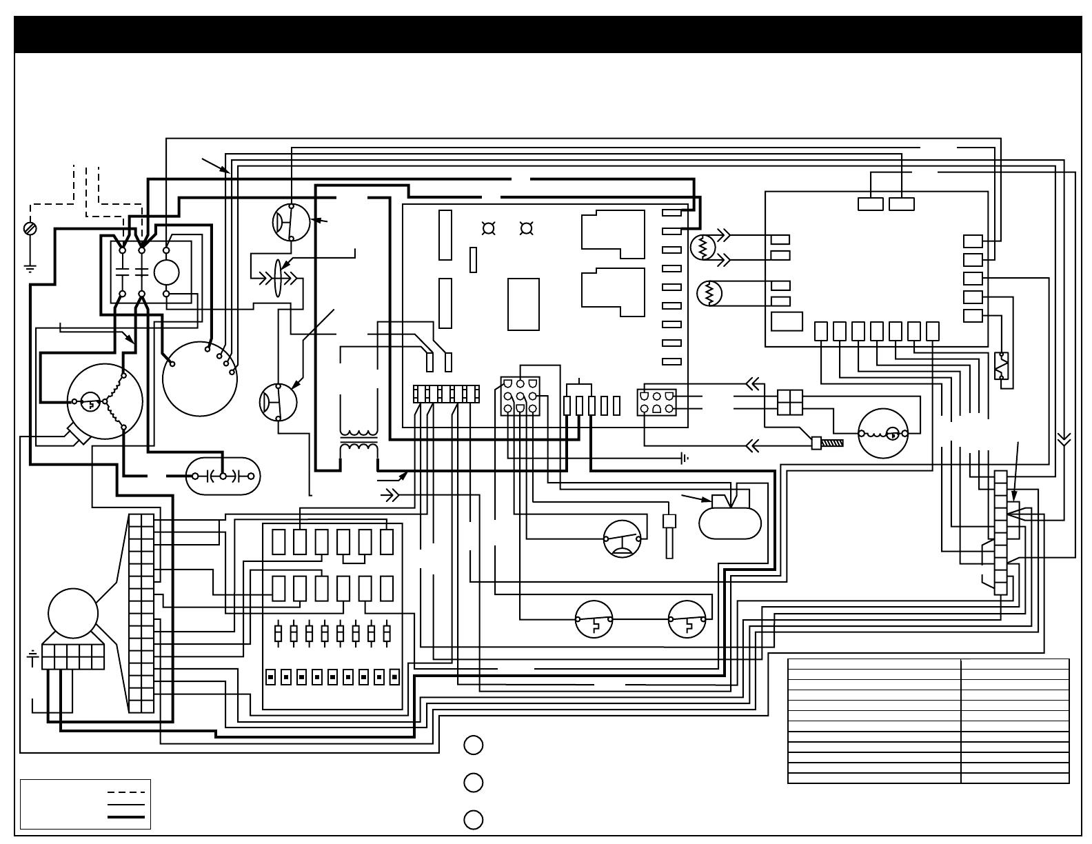
208/230 VoltDual Fuel Heating and Cooling Packaged System Single Phase / 60 Hz.
WIRING DIAGRAM
NOTES:
1. Disconnect power before servicing.
2. For supply connections use copper conductors only.
3. Not suitable on systems that exceed 150V to ground.
4. If any of the original wire as supplied with the furnace must be replaced,
it must be replaced with wiring material having a temp. rating of at least 105˚C.
5. For supply wire ampacities and overcurrent protection, see unit rating plate.
6. Ensure that wires from the blower remain connected to the board
thermostat terminals after making the field thermostat connections.
7110000
0909
FIELD WIRING
LEGEND:
LOW VOLTAGE
HIGH VOLTAGE
NOTES:
1. Couper le courant avant de faire letretien.
2. Employez uniquement des conducteurs en cuivre.
3. Ne convient pas aux installations de plus de 150 V
a la terre.
DEFROST BOARD OPERATION:
Heat Pump operates in heating mode until the combination of outdoor ambient
and outdoor coil temperatures initiate a defrost cycle. The outdoor coil
temperature must be at or below 32˚F before the defrost cycle begins.
There must be a minimum of 20 minutes between defrost cycles. After this
time, temperature conditions must call for defrost continuously for 4 1/2
minutes before a defrost cycle is initiated.
The defrost cycle ends when the outdoor temperature reaches 32˚F or the
defrost terminate time of 13 minutes 39 seconds is reached.
1
2
3
FAULT CONDITION STATUS LIGHT (RED)
Limit Circuit Open 1 Flash
Pressure Switch Stuck Open with Inducer On 2 Flashes
Pressure Switch Stuck Open with Inducer Off 3 Flashes
Ignition Failure (Check Ground) 4 Flashes
230 VAC & Neutral Reversed or No Ground 5 Flashes
False Flame or Gas Relay Shorted Continuous Flash
FAULT CONDITION STATUS LIGHT (YELLOW)
Low Flame Sensor Signal Continuous Flash
7. Wiring shown for single stage operation. For two stage operation, move brown wire from
low side of the gas valve to W2 on the terminal block and remove jumper from W1 to W2.
See installation instructions for an alternate means of controlling second stage.
8. A heat pump thermostat with fossil fuel back-up heat capability is REQUIRED for this system.
¢711000H¤
(Replaces 7109430)
