
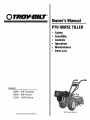
O TRO_YBILT
Models
12089 - 8HP Standard
12090 - 8HP Electric
12204 - IOHP Electric
GARDEN WAYINCORPORATED
Owner'sManual
PTOHORSETILLER
• Safety
• Assembly
• Controls
• Operation
• Maintenance
• PartsList
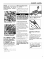
(8HP model shown)

DearOwner:
Younowownoneofthefinestrear-tinetillersavailable.
YournewPTOHorseModeltillerenablesyoutotilland
cultivateyourgardenwithease,andaccomplishdozensof
otherpropertymanagementprojectsaswell.ItsPTO
(PowerTakeOff)capabilityenablesittopoweravarietyof
attachments,includingachipper/shredderandalog
splitter.Yourtillerisfamousforitsruggedness,perfor-
manceandhigh-qualityengineering.Weknowyou'llenjoy
usingit.
PleasecarefullyreadthisManual.Ittellsyouhowtosafely
andeasilyassemble,operateandmaintainyourmachine.
Be surethat you and anyother operators carefully follow
the recommendedsafetypractices atall times. Failureto
do socould result in personal injury orproperty damage.
Ofcourse, if you should ever haveany problems or
questions, pleasecontact your local authorizedservice
dealeror call the Factory(seeback cover). Wewant to be
surethat you are completely satisfied at all times.
NOTE: Besure to fill out andreturn the Owner Registration
Cardincluded includedwith this manual.
See BackCoverfor
CustomerServiceInformation
Safety AlertSymbol
,_. This isa safety alert symbol, It is used in this
manualand on the unit to alert you to
potential hazards, Whenyou seethis symbol,
read and obeythe messagethat follows it.
Failureto obeysafety messagescould result in personal
injury or propertydamage.
This machine meets voluntary safety standard B71.8
- 1996, which is sponsored by the Outdoor Power
Equipment Institute, Inc., and is published by the
American National Standards Institute.
WARNING
The engine exhaust from this product contains
chemicals known to the State of California to cause
cancer, birth defects or other reproductive harm.
TABLEOFCONTENTS
SECTION1: SAFETY .................................................. 3
Training........................................................................................ 3
Preparation.................................................................................. 3
Operation..................................................................................... 3
Maintenanceand Storage............................................................ 5
Decals.......................................................................................... 5
SECTION2: ASSEMBLY.............................................. 6
Step 1: Unpacking Instructions.................................................... 6
Step 2:Attach Handlebar............................................................. 6
Step 3: MoveTiller Off Shipping Platform.................................... 7
Step 4:Connect Forwardinterlock Wire Harness......................... 7
Step 5:Attach Wheels/Tines/PTODriveLever.............................. 7
Step6: CheckGearOil Levels...................................................... 8
Step 7:Add Motor Oil to Engine................................................... 9
Step8: Attach EngineThrottle Lever andCable........................... 9
Step9: Adjust Air Pressurein Tires............................................. 9
Assembling TheElectric Start System......................................... 10
SECTION3: FEATURES& CONTROLS................................ 13
PTOAttachments Feature............................................................ 13
Wheels/Tines/PTODriveLever..................................................... 13
Forward InterlockLevers............................................................. 13
WheelSpeed Lever...................................................................... 14
Tine/PTOClutch Lever................................................................. 14
DepthRegulatorLever................................................................. 14
HandlebarHeight Adjustment Lever............................................. 14
EngineThrottle Lever................................................................... 15
KeyswitchStarter......................................................................... 15
EngineControls ........................................................................... 15
SECTION4: OPERATION.............................................. 16
Break-In Operation....................................................................... 16
Starting and Stopping the Engine................................................ 16
Operating the Tiller ...................................................................... 18
Testing the ForwardInterlock Safety System............................... 20
Loadingand Unloading the Tiller ................................................. 20
Changing SpeedBelts.................................................................. 21
Choosing WheelandTine Speeds................................................ 22
Tilling Tips & Techniques............................................................. 23
PTOPowerUnit ........................................................................... 27
PTOPowerUnit Operating Instructions ....................................... 28
SECTION5: MAINTENANCE.......................................... 30
RequiredMaintenance Schedule.................................................. 30
Tighten Bolts and Nuts................................................................. 31
Tiller Lubrication .......................................................................... 31
Transmission GearOil.................................................................. 32
Adding or Changing GearOil........................................................ 33
DriveBelt Maintenance................................................................ 35
ReverseDisc Maintenance........................................................... 37
Bolo Tine Maintenance................................................................. 39
Tine ShaftMaintenance................................................................ 41
Tire andWheelMaintenance........................................................ 41
EngineOil Maintenance................................................................ 41
Air CleanerMaintenance.............................................................. 41
Throttle CableMaintenance.......................................................... 41
Ignition System Maintenance....................................................... 41
Spark Plug Maintenance.............................................................. 41
BatteryCareandMaintenance..................................................... 41
Storing your Tiller........................................................................ 43
inspecting Forward Interlock Wiring System............................... 43
Testing the Forwardinterlock Wiring System.............................. 43
APPENDIX A: TROUBLESHOOTING...................................... 44
APPENDIX B: ATTACHMENTS & ACCESSORIES....................... 46
PARTSLIST............................................................... 47
CUSTOMERSERVICEINFORMATION.............. Back Cover
2

S
........................................Safety
SPARKARRESTERWARNINGTORESIDENTSOFCALIFORNIAAND SEVERALOTHERSTATES
UnderCalifornia law, and under thelaws of severalother states,you are not permitted to operatean
internal combustion engine using hydrocarbon fuels on anyforest, brush, hay, grain, or grass
covered land;or land covered by anyflammable agricultural crop without an enginespark arrester in
continuous effectiveworking order.
The engineon the unit isan internal combustion engine which burns gasoline, a hydrocarbon fuel, and must be equippedwith a
spark arrester muffler in continuous effectiveworking order. Thespark arrester must beattachedto theengine exhaustsystem in
such a mannerthatflames or heatfrom the systemwill not ignite flammable material. Failureof the owner/operator of theunit to
comply with this regulation isa misdemeanor under California law (and other states) and may also be aviolation of other state
and/or federalregulations, laws, ordinancesor codes. Contactyour localfire marshal or forest servicefor specific information
aboutwhich regulations apply in your area.
Training
1. Carefullyreadthis Owner's Manual,the
separateEngineOwner'sManual, and any
other literature you may receive.Be thor-
oughly familiar with thecontrols and the
proper useof thetiller and its engine.
Know how to stop the unit and disengage
the controls quickly.
2. Neverallow children to operatethe
tiller. Neverallow adults to operatethe
tiller without proper instruction.
3. Keepthe areaof operation clearof all
persons,particularly children and pets.
4. Keepin mind that the operator or user
is responsible for accidentsor hazards
occurring to other people,their property,
and themselves.
Preparation
1. Thoroughly inspect the areawherethe
tiller is to be usedand remove all foreign
objects.
2. Putthe Wheels/Tines/PTODrive Lever
into NEUTRALbeforestarting theengine.
3. Donot operatethe tiller without
wearingadequateouter garments. Avoid
loose garmentsorjewelry that could get
caught in moving parts.
4. Donot operatethe tiller when barefoot
or wearingsandals,sneakers,or light
footwear. Wearprotective footwear that
will improve footing on slippery surfaces.
5. Donot till nearunderground electric
cables,telephonelines, pipesor hoses.If
in doubt, contact your telephoneor utility
company.
6. Warning:Handlefuel with care;it is
highly flammable and its vapors are
explosive. Besureto takethe following
precautions:
a,
b.
Storefuel in containers specifically
designedfor this purpose.
The gascapshall neverbe removed
or fuel addedwhile the engine is
running. Allow the engine to cool
for severalminutes before adding
fuel.
C,
Keepmatches,cigarettes, cigars,
pipes, open flames, and sparks
awayfrom thefuel tank and fuel
container.
d. Fillfuel tank outdoors with extreme
care. Neverfill fuel tank indoors.
Use afunnel or spout to prevent
spillage.
e. Replaceall fuel tank and container
caps securely.
f. If fuel is spilled, do not attempt to
start the engine,but move the
machine awayfrom thearea of
spillageand avoid creating any
source of ignition until fuel vapors
havedissipated.
7. Nevermake adjustmentswhen engine
is running (unlessrecommendedby
manufacturer).
Operation
I. Do not put handsor feet near or under
rotating parts. Donot allow handsor any
other part of the bodyor clothing near the
rotating tines or near anyother moving
part. Thetines beginto rotate forward
oncethe enginestarts, the Tines/PTO
ClutchLeveris in the ENGAGEposition,
the Forward Interlock Leversare squeezed
closed andthe Wheels/Tines/PTODrive
Leveris shifted to FORWARD.Thetines
rotate in Reversewhether the Interlock
Leversare closed or open.
2. Exerciseextremecaution when on or
crossing graveldrives, walks, or roads.
Stayalert for hidden hazardsor traffic. Do
not carry passengers.
3,After striking aforeign object, stop the
engine,removethe wire from thespark
plug wire and prevent it from touching the
spark plug. Thoroughly inspectthe
machinefor anydamageand repair the
damagebefore restarting and operating
the machine.
4, Exercisecaution to avoid slipping or
falling.
5. If theunit should start to vibrate abnor-
mally, stop the engine,disconnect the
spark plug wire andprevent it from
touching the spark plug, and check imme-
diatelyfor the cause.Vibration is
generallya warning of trouble.
6. Stopthe engine,disconnect the spark
plug wire and prevent it from touching the
spark plug wheneveryou leavethe
operatingposition, before unclogging the
tines, or when making any repairs, adjust-
ments or inspections.
7. Takeall possible precautionswhen
leavingmachine unattended.Stopengine.
Disconnectspark plug wire and move it
awayfrom spark plug. Removeignition
keyon electric start models

Section1: Safety
8. Beforecleaning, repairing,or inspect-
ing, stop theengine and make certain all
moving parts havestopped. Disconnect
the spark plug wire and prevent it from
touching thespark plug to preventacci-
dentalstarting.
9. Theflap on the fine hood must be
down whenoperating the tiller, unless
using the HillerlFurrower attachment.
10. Neverusethe tiller unless proper
guards, plates,or other safety protective
devicesare in place.
11. Donot run engine in anenclosed
area.Engineexhaustcontains carbon
monoxide gas, a deadlypoison that is
odorless, colorless, and tasteless.
12. Keepchildren and pets away.
13. Neveroperatethetiller underengine
power if the WheelSpeedLeveris in the
FREEWHEELposition. In FREEWHEEL,
thewheels will not hold the tiller backand
the revolving tines could propel the tiller
rapidly, possibly causing loss of control.
Alwaysengagethe WheelSpeedLeverin
either FASTor SLOWposition before
starting the engine or engaging the tines
with theWheels/TineslPTODrive Lever.
14. Beawarethatthetiller mayunex-
pectedly bounceupwardorjump
forward ifthetines shouldstrike
extremelyhardpackedsoil, frozen
ground,or buriedobstacleslike large
stones,roots, orstumps.If in doubt
aboutthetilling conditions,alwaysuse
thefollowing operatingprecautionsto
assistyouin maintainingcontrolof the
tiller:
a. Walk behindandtoone side ofthe
tiller, usingonehandonthehan-
dlebars.Relax yourarm, but usea
secure handgrip.
b. Useshallower depthregulator
settings, workinggraduallydeeper
witheachpass.
c. Useslowerwheel, fine and engine
speeds.
d. Clearthe tilling areaof all large
stones,rootsand otherdebris.
e. Avoidusingdownwardpressureon
handlebars.Ifneed be, useslight
upwardpressureto keepthe tines
from diggingtoodeeply.
f_
Beforecontactinghardpackedsoil
at the endof a row, reduceengine
speed and lift handlebarsto raise
tines outofthe soil.
g. In an emergency,stop tines and
wheels byshifting the
Wheels/Tines/PTODriveLever
intoNEUTRAL.If youcannot
reachthe lever orhave lostcontrol
ofthetiller, let goof thehandle-
barsand all controls. Do not
attempttorestrainthetiller.
15. Do not overloadthe filler's capacityby
attempting to till too deeplyat too fast a
rate.
16. Neveroperatethe tiller at high
transport speedson hard or slippery
surfaces. Look behindand usecarewhen
backing up.
17. Do not operatethe tiller on aslope
that is too steep for safety.When on
slopes, slow down and makesureyou
havegood footing. Never permit the tiller
to freewheel down slopes.
18. Neverallow bystandersnear theunit.
19. Onlyuse attachmentsand accessories
that areapproved bythe manufacturer of
the tiller.
20. Usetiller attachments and acces-
sories when recommended.
21. Neveroperatethe tiller without good
visibility or light.
22. Neveroperatethe tiller if you are
tired, or under the influence of alcohol,
drugs or medication.
23. Operatorsshall not tamper with the
engine-governor settings on the machine;
the governor controls the maximum safe
operating speedto protect the engine and
all moving parts from damagecausedby
overspeed. Authorized serviceshall be
sought if a problem exists.
24. Do not touch engineparts which may
be hot from operation.Let parts cool
down sufficiently.
25. POISON/DANGER--CAUSES
SEVEREBURNS.Thebattery on electric
start models contains sulfuric acid. Avoid
contact with skin, eyesor clothing. Keep
out of reachof children.
Antidotes:
External- Flushimmediately with lotsof
water=
Internal- Drink largequantities of water
or milk= Followwith milk of magnesia,
beateneggsor vegetableoil. Calla
doctor immediately=
Eyes- Flushwith water for 15 minutes=
Get prompt medical attention=
26. DANGER-BATTERIESPRODUCE
EXPLOSIVEGASES. Keepsparks, flame
or smoking materialsaway. Ventilate
when charging battery or using in an
enclosed space. AIwayswearsafety
goggles whenworkingnear battery.
27. Pleaseremember:You canalways
stop the tines and wheels by releasingall
controls, or bymoving the ignition switch
andlor throttle control leveron the engine
to OFFor STOP.
28. To load or unload the tiller, seethe
instructions in Section 4 of this Manual.
29. Useextremecaution whenbacking or
pulling the machinetowards you.
30. Startthe enginecarefully according to
instructions andwith feet well awayfrom
the tines.
31. Neverpick up or carry a machine
while the engine is running.
32. When loading or unloading the tiller,
alwaysdisengagetines anduse slower
wheel and enginethrottle speeds. Use
sturdy ramps wide and strong enough to
easily support the tiller (280-to-325 Ibs.,
depending on model) and operator.
Nevergo down ramps in FORWARD
drive--the tiller could tip forward,
exposing you to the tines (which should
be disengaged). AIwaysuse REVERSE
drive and backdown ramps. Togo up
ramps, useFORWARDdrive and follow
the tiller.
33. TheForward Interlock SafetySystem
should betested for correct functioning
every time thetiller or PTOpower unit is
used. SeeSection 4 in this Manual.
34. If using the optional Dozer Blade,
either removethe tine attachment,or
disengagethe tines with the TineslPTO
Clutch Lever= Revolvingtines are
dangerous.

Section1: Safety
Maintenance and Storage
1. Keepthe tiller, attachments and acces-
sories in safe working condition.
2. Checkall nuts, bolts, and screws at
frequent intervalsfor proper tightness to
be sure theequipment is in safeworking
condition.
3. Neverstore the tiller withfuel in the
fuel tank insidea building where ignition
sources are present such ashot water
and space heaters,furnaces, clothes
dryers, stoves, electricmotors, etc.).
Allow engine to cool before storing in any
enclosure.
4. To reducethe chancesof afire hazard,
keepthe enginefree of grass, leaves,or
excessivegrease.
5. Store gasolinein a cool, well-ventilated
area,safelyaway from any spark- or
flame-producing equipment. Store
gasolinein anapprovedcontainer, safely
awayfrom the reachof children.
6. Referto the Maintenancesections of
this Manualandthe separateEngine
Owner's Manualfor instructions if the
tiller is to be stored for an extended
period.
7. Neverperform maintenancewhilethe
engine is running or the spark plug wire is
connected, exceptwhen specifically
instructed to do so.
8. If thefuel tank hasto be drained,do
this outdoors.
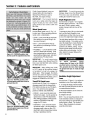
Decals A) WARNING:HotSurfaces. C) WARNING:Operatingand
Foryour safety andthe safety of others, Topoftheair cleanerhousing. SafetyInstructions
various safetyand operational decalsare
located on your unit (Figure1)=
Keepthe decalscleanand legible at all
times. Contact your local servicedealer
or the Factoryfor replacementsif any
decals aredamagedor missing.
D) Power Unit
Referto the Parts List for decal locations,
descriptions and part numbers.
F) EngineStabilization.
Topoffuel tank.
B) WARNING:EngineIgnition.
Electricstart modelsonly.
Figure1:LocationofSafetyand OperatingDecals.
(Briggs & Strattonengineshown)
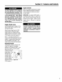
OperatingSymbols
Varioussymbols (shown here,with word
descriptions)areusedonthetilleranderoine.
Yourunitmaynothaveallofthesymbols.
H I÷1
FAST SLOW CHOKE CHOKE
STOP ON OFF
ROTATING
TINES
TO AVOID SERIOUS INJURY:
• READTHEOWNER'SMANUAL.
• KNOWLOCATIONSAND FUNCTIONSOFALL CONTROLS.
• KEEPALLSAFETYDEVICESANDSHIELDSIN PLACEANDWORKING.
• NEVERALLOWCHILDRENOR UNINSTRUCTEDADULTSTOOPERATETILLER.
• SHUTOFFENGINEAND DISCONNECTSPARKPLUGWIRE BEFOREMANUALLYUNCLOG-
GINGTINES ORMAKINGREPAIRS.
• KEEPBYSTANDERSAWAYFROMMACHINE.
• KEEPAWAYFROMROTATINGPARTS.
• USEEXTREMECAUTIONWHENREVERSINGORPULLINGTHEMACHINETOWARDSYOU.

!1
Assembly
To prevent personal injury or property
damage, do not start the engine until
all assembly steps are complete and
you have read and understand the
safety andoperating instructionsin this
manual.
Introduction
Carefullyfollow these assembly stepsto
correctly prepareyour tiller for use. It is
recommendedthat you readthis Section
in itsentirety beforebeginning assembly.
NOTE:Varioustiller models are presented
in this Manual. Useonly the information
appropriatefor your tiller model,
Inspect Unit
Inspectthe unit and carton for damage
immediatelyafter delivery, Contactthe
carrier (trucking company) ifyou find or
suspect damage. Inform them of the
damageand request instructionsfor filing
a claim. To protect your rights, put your
claim in writing andmail a copy to the
carrier within 15days after the unit has
beendelivered. Contact usat the Factory
if you needassistancein this matter.
STEP1: Unpacking Instructions
NOTE:Donot severelybend anyof the
control cables on the unit.
I. Thetiller is heavy. Do not attempt to
remove it from the shipping platform until
instructed to do so in these Assembly
steps.
2. Removeall unassembledparts from
the carton. Thehardwarebag is included
in your literature packaging.
3. If you orderedan ElectricStart Tiller,
remove the hardwarebag from under the
battery clamp (A,Figure2-16).
4. Checkthat you havethe items listed
below (contact your local dealeror the
6
Factory if anyitems are missing or
damaged).
NOTE: Usethe screw lengthtemplate
(Figure2-1) to identify screws.
LoosePartsList
Qty. Description
1 HandlebarAssembly
1 Wheels/TinesPTODrive Lever
Thefollowing items
are in the hard-warebag:
1 Clutch PawlSpring
1 BeltAdJustingTool
2 PlasticCableTies
1 Curved HeadScrew, 1/4-20 x 2
1 FlangedLock Nut, 1/4-20
1 PanHeadScrew,#20-24 x 1/2
Thefollowing parts (electric start models
only/),packagedseparately,are located
under the batteryclamp,
2 Nuts, I/4-20
(for battery terminals)
2 Screws, I14-20 x 518
(for battery terminals)
1 BatteryVent Tube
2 Keys
(Fnignition switch)
IMPORTANT:Motor oil must be added to
the engine crankcase beforethe engine is
started. Follow the instructions in this
Assembly Section and in the separate
EngineOwner's Manual.
NOTE:LEFTand RIGHTsides of thetiller
are asviewedfrom the operator's
position behind the handlebars(unless
otherwise noted).
Tools/Materials Needed
for Assembly
(1) 3/8"open-end wrench*
(2) 7/16"open-end wrench*
(2) 1/2"open-end wrench*
(1) 9/16°open-end wrench*
(1) 3/4"open-end wrench*
(1) Flatbladescrewdriver
(1) Scissors (to trim plastic ties)
(1) Tire pressure gauge
(1) Cleanoil funnel
(1) Motor Oil. Referto the Engine
Owner's Manualfor motor oil spec-
ifications and quantity.
(1) 4-1/2" highwood block (or other
sturdy block) to prop unit
* Adjustable wrenchesmay be used.
Figure2. I: Toidentifylengthof screw,
place screwon templateas shownand
measuredistance betweenbottomof screw
headand tipof screw.
STEP2: Attach Handlebar
IMPORTANT: When disassembling
handlebar assembly, keep left-side clamp
and ratchet separatedfrom the right-side
clamp and ratchet.
I. Disassemblethe handlebarassembly.
To do this, remove the heightadjustment
leverby turning the leverin acounter-
clockwise direction (Figure2-2).

Section2: Assembly
2. Placethe handlebarends on either side
of the base,with the wire harnesstoward
the rear of the base(Figure2-2).
3. Installthe height adjustment lever
through the right-side clamp, handlebar
end, ratchet, and base;then out through
the left-side ratchet, handlebar end,and
clamp (Figure2-2). Securewith nut, but
don't fully tighten.
IMPORTANT:Donot force the height
adjustment leverthrough the handlebars.
Theinterlock wires may be blocking the
leverand could be damaged.Youmay
gently move thewires asideif this
condition occurs.
4. Raisehandlebarsto one of two height
settings and tighten the height adjustment
lever. Also, make sureall other mounting
hardware is securelytightened.
NOTE: Fully assembledhandlebar
assembly should appearas shown in
Figure2-3.
Figure 2-3. Fully assembled handle.
bars.
STEP3: Move Tiller Off Shipping
Platform
1. Setthe Depth Regulator Lever
(A, Figure2-4) to Travel position. Dothis
by lifting the tiller by the handlebars,then
pulling straight back on the leverand
sliding down to the highest notched
setting.
2. Setthe WheelSpeedLever (B,Figure
2-4) to Freewheelposition. To do this,
move the leverapproximately halfway
betweenthe Fastand Slow settings while
you rock the tiller forward and backward
until thewheels movefreely.
3. Lift Handlebarshigh enough to clear
tiller tines and pull back firmly to dislodge
the tiller from the platform wheel wells.
Right
Height
Adjustment Base
Lever
FRONT
OFTILLER
Figure 2-2. Handlebar assembly.
Figure 2.4: Photo shows the Depth
Regulator Lever (,4) and the Wheel
Speed Lever (B).
STEP4: Connect Forward
Interlock Wire Harness
I. Removeanydirt from the Forward
Interlock wire harness plug (C, Figure
2-6) and its receptacle(D).
2. Connectthe Forward Interlock wire
harness plug (C, Figure2-6) to the recep-
tacle (D).
STEP5: Attach
Wheels/Tines/PTO Drive Lever
I. Loosenthe bolt (Figure2-2) on the
handlebar baseand swing the handlebars
out to the right side.
Handlebars
Left
Clamp
Nut
Wire
Harness
Figure 2.5. Forward Interlock Wire
Harness connection.
2. Removeboth sets of nuts, star
washers, screws, and one bushing
(A, B,C, D, E,F,G, Figure2-6) from the
yoke plates (H). Thereis a bushing inside
the short link (I). Becareful not to lose it
when removing screw (G).
3. Slide the plates atthe end of the
Wheels/Tines/PTOLeverover theyoke
plates (Figure2-9). To aid in the next
step,insert a screwtemporarily into the
forward most holes (J, Figure2-7) of the
yoke plates and the lever.
4. Align the rear most holesof theyoke
platesand the WheelslTineslPTOLever.
Uselong nosepliers to hold the bushing
(L, Figure27) in placewhile inserting the
screw (K) through the leverand yoke
plates.Install star washer (B, Figure2-6)
andnut (A), then handtighten.
5. Retrievethe clutch pawl spring (Figure
2-8) from hardwarebag.

Section2: Assembly
Removethe temporary screw (J, Figure
2-7) from the forward holes and move the
Wheels/Tines/PTOLeverfully forward.
Install the wider hook end of the clutch
pawlspring (M, Figure2-8) down into the
small holeat the end of the handle. Use
pliers to insert the other end into the hole
in the long link bar (N).
NOTE:Do not bend or over stretch the
spring while installing,
6. Pull the Wheels/Tines/PTOLeverback
to align the forward most holes (Q,Figure
2-9) in the yoke platewith the holes in the
leverplates. Also align the bushing that is
insidethe short link bar (P). Install the
screw, star washer, and nut, then tighten
securely.
Securelytighten all other hardware (Q,R,
Figure2-9). Alsoensure that the spring
(S) is properly seatedat both ends.
Completedassembly should appearas
illustrated in Figure2-9,
7. Testthe operation of the
Wheels/Tines/PTOLever. Pushthe lever
down until it engagesin the Forward
position. The clutch roller (T, Figure2-
10) must rest beneaththe adjustment
block (U). Next,move the lever upto the
Neutralposition. Theclutch roller (T,
Figure2-I I) should rest on theface of the
adjustment block (U). To test Reverse,lift
and hold the leverall the way up in
Reverseposition, then let it go. Thelever
should automaticallyreturn to the Neutral
position (Figure2-11). If not, do not use
the tiller. Seeyour localauthorized dealer
or call the FactoryTechnicalService
Departmentfor instructions.
Figure 2.9: Fully assembled
WheelslTines/PTO Lever assembly.
Figure 2.10 Forward position; roller
(T) rests under the adjustment
block (U).
Figure 2-6: Illustration shows the yoke plates (H), nuts, washers, and
screws (A, E, B, F, D, G), bushing (C), and long and short links (I, J).
Figure 2-7: Drive Lever assembly.
Figure 2.8: Clutch pawl spring. Tilt
Wheels\Tines_PTO Lever fully
forward before installing spring.
Figure 2.11: Neutral position; roller
(T) rests against middle area of the
adjustment block (U).
STEP6: Check Gear Oil Levels
Your tiller hastwo separatetransmis-
sions: one for the Power Unit (Figure2-
12), the otherfor the TineAttachment
(Figure2-13). Both transmissions were
filled at thefactory with SAE#85W-140
weight gear oil (with an A.P.I rating of
GL-4). Checklevelin both transmis-
sions to verify that they are still correct.
SeeSection 5, TransmissionGearOil
Maintenancefor complete information
on how to check and fill the transmis-
sions.

Section2: Assembly
IMPORTANT:Checkgear oil level in both
transmissions after the first 2 hours of
new tiller operation, then every 30
operating hours thereafter. SeeSection 5
for instructions.
Figure 2-12: Checking oil level on
Power Unit Transmission.
Figure 2.13: Checking oil level on
Tine Attachment Transmission.
STEP7: Add Motor 0il to Engine
I. Beforeadding motor oil, park thetiller
on levelground. Levelthe engine by
placinga sturdy block under thetines or
the tines depth regulator bar.
2. Add high-quality, APl-rated motor oil
to engine beforestarting. Referto the
EngineOwner's Manualprovided with
your tiller for detailed information on how
to add motor oil and for motor oil
specifications.
IMPORTANT:
• Changeengine oil after first 2 hours of
newoperation.
• Checkengine oil levelevery 5 hours of
operationor eachuse.
STEP8: Attach Engine Throttle
Lever and Cable
Forshipping purposes,the throttle cable,
together with the throttle lever, is wound
around the engine. Carefullyunwind the
cable. If the throttle control label is
coveredwith a clearprotective coating,
peel it off.
To avoid electric shock from a short
circuit (electric starttillers only), never
allow the throttle cable to touch the
battery. Routecable belowthe battery,
onthe outsideof thebatteryholder.
To attachthe throttle leverand cable:
I. Runthe throttle cableup the inside
edge of the right handlebarand position
the leverasshown in Figure2-I 4.
2. Fromthe outside of the handlebar,
insert the curved headscrew (A, Figure2-
14), through the handlebarand the center
hole in the throttle levermounting
bracket.
3. Loosely install the flanged lock nut
and move the throttle leverback to the
STOPposition.
4. Fromthe lever sideof the bracket,
thread a pan headscrew (B, Figure2-14)
through the small hole in the throttle lever
bracket and into the handlebar. Tighten
the screw securely.
5. Securelytighten both theflanged lock
nut and the curved head screw.
6. Usetwo plastic ties to securethe
throttle cableto the right handlebarin two
places (Figure2-15). Loop eachtie
around the handlebarand cable (serrated
side facesin) and pull theties tight. Trim
the ends.
B
Figure 2-14: Engine Throttle Lever
position and installation.
Figure 2.15: Plastic Ties placement
on handlebars.
STEP9: Adjust Air Pressure in
Tires
Forshipping purposes,the tires may be
overinflated. Checkthe air pressure in
eachtire andadjust them to between10
and20 pounds per square inch=You
must inflate eachtire to equalair
pressuresto prevent thetiller from pulling
to one side.
Assembly is complete for recoil start
tillers. SeeAssembling TheElectric
Start System if you own an electric
start tiller; otherwise, refer to Section
3, Controlsfor information on tiller
controls.

Section2: Assembly
ASSEMBLINGTHEELECTRICSTARTSYSTEM
Thefollowing stepsexplainhow to activate, charge,and install the battery on electric start tillers. Foryour safety,follow all steps
and observeall accompanying safetymessages. Section 5 contains other generalbattery maintenanceand recharging instructions.
STEP1: Activating and
Charging the Battery
IMPORTANT: The battery is shipped dry.
It needs battery electrolytic fluid (battery-
grade sulfuric acid). It must then be fully
charged with a battery charger before
use,
Adding electrolytic fluid to the batteryand
charging the batterycan be dangerous.
Electrolytic fluid contains acid that can
burn or blind you. Batterycharging also
produces explosivegases.
To ensurethat the battery is properly
activatedand charged, you should review
these instructions with your battery
technician.
IMPORTANT: It is strongly recom-
mended that you have the battery
activated and chargedby a trained profes-
sional (Troy-Bilt Dealer, service station,
farm equipment dealer, etc.), if you are
not experiencedwith these procedures.
Battery electrolytic fluid is
poisonous and burnsseverely.
Electrolytic fluid is a sulfuric acid
solution. Avoid spills or contact with
skin, eyes,clothing.
• To prevent accidents,wear protective
clothes, rubber gloves and shield
eyes with safety goggles when
workingonor nearthe battery.
• Neutralize acid spills with a baking
soda and water solution. Neutralize
electrolyte container with same
solution. Thenrinsewith clear water.
• Antidote:External- Flush with water;
Eyes- Flushwith waterfor 15 minutes
andget immediatemedicalattention.
• Antidote: Internal- Drink large
quantityof wateror milk. Followwith
milk of magnesia, beaten eggs, or
vegetableoil. Call a doctorimmedi-
ately.
Batteryproducesexplosivegases.
• Keep away sparks, flames, and
cigarettes.
• Ventilate areawhen chargingor using
batteryin an enclosedspace.
• Make sure batteryventtube is always
openafterbatteryisfilled with acid.
TOACTIVATETHEBATTERY:
Remove metal jewelry before working
near the battery or near the electrical
system. Failure tocomplymaycausea
short circuit, resulting in electrical
burns, a shock, or battery gas
explosion.
For shipping purposes,the battery and its
hold-down clamp (A,Figure2-16) were
installed backwards atthe factory. When
reinstalling the batteryand hold-down
clamp, be sureto facethem in the
opposite direction from which theywere
shipped.
A
Figure2.16: Batteryshown installed
backwardsforshippingpurposesamy.
I. Removethe two I-I12" long screws
and thetwo I/4" whiz nuts that securethe
front and rear hold-down clamp legsto
the battery bracket(C, Figure2-16).
Lift off the clamp and removebattery.
Savethehardware.
2. If installed, remove anddiscard the
short, plastic tubing (B, Figure2-16) that
covers the vent fitting on the negative-
sideof the battery.
3. Placethebattery on a levelwork
surface,far awayfrom heator flame
sources likestoves,water heaters,dryers,
and furnaces.
4. Removethe six filler caps (D, Figure
2-17) on top of thebattery.
IMPORTANT: Be sure to wearing protec-
tive clothes, rubber gloves, and eye
protection.
5. Filleachcell to the Upper Levelline
printed on the batterycase (E, Figure2-
17) using battery-gradeelectrolytic
solution. (This is 1.265specific gravity
sulfuric acid.) Temperatureof battery and
electrolytic fluid is idealwhen between
60°Fand 80°F. Donot add water or any
other liquid to the batteryduring this
initial activation.
Figure 2-17: Illustration shows filler
caps (D) and Upper Level fill line (E).
6. Let batterystand for 30 minutes.
Checkelectrolytic fluid levelin eachcell.
Add morefluid, if needed=Do not overfill
battery- this could leadto flooding from
the cells during charging=
10

Section2: Assembly
TOCHARGETHEBATTERY:
1. Useone of the three charging methods
described belowfor maximum starting
capacityand longest battery life.
NOTE:Bubbling (gassing freely) elec-
trolyte solution within the battery cells
indicates that the battery ischarged.
Thesebubbles emit toxic gasesthat
escapefrom the cells when you remove
the cell caps. Always wearsafety goggles
to protectyour eyeswhen checkingfor
bubbles. A flashlight makesthe inspec-
tion easier. Inspect all cells.
To Avoid Personal Injury or Property
Damage:
• Batteries produce explosive gases -
always keep sparks and flame away
from battery.
• Ventilate area when chargingor using
thebattery.
• During charging, do not leave battery
unattended. Charging time need not
becontinuous.
• Follow safety rules and instructions
supplied by battery and charger
manufacturers.
• Do not chargebattery at a rate higher
than 12 amperes to avoid generating
excessive heat and gassing which
coulddamagethe battery.
• Our RecommendedMethod:
Chargethe batteryat a rateof 14o-2
amperesuntil all cells bubble freely. Do
not exceed24 hours chargetime.
• FirstAlternative ChargingMethod:
Chargethe batteryat a rate of 440-6
amperesuntil all cells bubblefreely. Do
not exceed8 hours chargetime.
• SecondAlternative ChargingMethod:
Chargethe batteryat a rate of
6-to-12 amperesuntil all cells bubble
freely. Do not exceed4 hours charge
time.
2. Turn offthe charging equipment and
disconnect the chargercables from the
batteryterminals.
3. Recheckelectrolyte levelin eachcell.
Top off anylow cells with electrolyte
solution up to the "Upper" level line.
4. Securelyreplaceall six filler caps. Use
a baking sodaand water mixture to rinse
off electrolytic fluid that may havespilled
on the battery.
STEP 2: Connect the Wire
Harness Receptacle
I. Beforeinstalling the batteryand its
hold-down clamp, insert the plastic wire
harness receptacle(A,Figure2-18) into
the prongs of the keyswitch (B) located
on the hold-down clamp.
2. Removethe ignition keysfrom the
keyswitch and store them safelyaway=
Do not insert the key intothe keyswitch
until you completethis section and read
Section 3, Controls.
STEP3: Installing the Battery
1. Carefullyplacethe activatedbattery
back on the battery mounting platform
(C,Figure2-18). Facethe side of the
batterywith the terminals posts and the
fill linesto the rear of the tiller. The
positiveterminal (marked +)should be on
the left sideof the tiller when standing
behindthe handlebars.
To Avoid Personal Injury or Property
Damage:
• Do not touchpositive battery terminal
and any surrounding metal objects
with tools, jewelry or other metal
items. Failure to complycouldcause
a short circuit leading to electrical
burnsor explosionof batterygases.
• Neverbringa gascannear thepositive
(+) battery terminal. A short circuit
couldoccurleadingto an explosionof
the gasoline or the battery gases.
Always fill the engine fuel tank from
thefront or side ofthe engine.
2. Placethe batteryhold-down clamp (D,
Figure2-18) overthe battery. Usetwo
screws (H) and whiz nuts (I) to secure the
two legsto the platform (C). Insert the
screws up from thebottom. Tightenthe
hardwarebut do not overtighten. (The
clamp tabs will bend if screwsare over-
tightened.)
Improper battery venting can cause a
battery to explode resulting in severe
personalinjury. Besurethe venttube is
notcrimped, pinched,folded, or blocked
inanyway.
3. To install thevent tube (E,Figure2-
18), slide one end of the tube overthe
vent fitting (F)=Uncoil the tube andslide
theother end down into the black vent
tube shield (G).
Neverjump start the battery with a
vehiclebatteryor chargingsystem.This
may produce a battery explosion,
causingacid or electricalbums.
Figure 2-18: Battery mounting and venting assembly. 11

Section2: Assembly
STEP 4: Install the
Battery Cables
NOTE:Thecableterminals should be
toward the rear (keyswitch side) of the
battery posts.
1. Usea 5/8" long screwand 1/4-20 hex
nut to connect the positive (+) battery
cable(J, Figure2-19) to the positive
(marked +) battery post (K). Makesure
that this is the cableon the left side, with
one end attachedto the solenoid (Q).
2. Slidethe black rubber boot (P) com-
pletely overthe battery post and cable
connector.
3. Usea 5/8" long screwand 1/4-20 hex
nut to connect the negative(-) battery
cable(L) to the negative (marked -)
battery post (M) and securewith screw
(R) and nut (S),
4. Slidethe black rubber boot (T) com-
pletely overthe battery post and cable
connector.
5. Makesurethat the lower end of the
vent tube shield (U) is positioned in front
of the wheelshaft axle. Move it there if
necessary.
Assembly is complete for electric start
tillers. SeeSection 3, Controlsfor
information on tiller controls.
N
Figure 2.19: Battery cable assembly.
12

n
FeaturesandControls
Before operating your machine,
carefully read and understand all
safety, controls, operating instructions
in this Manual, the separate Engine
Owner's Manual and on the decals on
themachine.
Failure to follow these instructionscan
resultin seriouspersonalinjury.
Introduction
This sectiondescribesthe location and
function of the controls and features on
your tiller. Refer to Section 4, Operation
for detailedoperating instructions.
Practiceusing thesecontrols, withthe
engine shut off, until you completely
understand the operationof thecontrols
and feelconfident with eachof them.
IMPORTANT:Referto the separateengine
manufacturer's Engine Owner's Manual
for information about the controls on the
engine.
NOTE:All referencesto left,right, front
and rearof the machineare basedon a
position behindthehandlebarsandfacing
forward.
PTO Attachments Feature
In additionto powerful tilling capability,
you can quickly convert your machine
into a PTO(PowerTake-Off) Power Unit
that is capableof towing or powering
various TROY-BILTattachments.
You can accessthis capabilityby
removing thetines attachment (powered
by the PTOPower Unit). ThePTOPower
Unit is then availablefor enginepowered
attachments,or for pulling or towing non-
poweredattachments. SeeSection4,
PTOPower Unitfor detailedinformation
on installing andoperating TROY-BILT
PTOattachments.
Wheels/TineslPTO Drive Lever
Usethe Wheels/Tines/PTODrive Lever (A,
Figure3-1) to engageand disengage
power to the transmission.
Figure 3-1:
A- WheelslTineslPTO Drive Lever
B- Forward Interlock Levers
C- Wheel Speed Lever
D- Tines/PTO Clutch Lever
This leverhasthree operatingpositions:
FORWARD,NEUTRALand REVERSE.
FORWARDisengagedwhen the leveris
moved down until the clutch roller (G,
Figure3-2) engagesintothe detent
position under the adjustment block (H,
Figure3-2). You will definitely feelthe
leverengageinto this position.
Usethe FORWARDsetting to move the
wheels andtines forward, or to apply
power to an optional PTO(PowerTake
Off) attachment. (Seealso Forward
InterlockLevers.)
To stop the wheels,tines or anyPTO
attachment,movetheleverto NEUTRAL
by tapping the leverupwards (Figure
3-3) and releasing.
• REVERSEis engagedwhen the lever is
pushed (with an open palm) all the way
up and held in that position (Figure3-4).
Usethis setting to move thewheels in
reverse. To stop moving in reverse,
releasethe lever; it automatically returns
to the NEUTRALposition.
zG
E- Depth Regulator Lever
F- Handlebar Height Adjustment Lever
G- Engine Throttle Lever
IMPORTANT: Do not operatethe tines or
anyPTOattachment in REVERSE.
• NEUTRAListhis control's normal non-
operating position. Theleverreturns to
NEUTRALwhen it is tappedout of the
FORWARDposition or releasedfrom the
REVERSEposition. NEUTRALposition
is between FORWARDand REVERSE
(Figure3-3). Usethis setting to stop
the wheels,tines or any PTOattach-
ment.
IMPORTANT: Always shift to NEUTRAL
before starting the engine or before
engaging the wheels, tines or any PTO
attachment.
Forward Interlock Levers
The Forward Interlock Levers (B,
Figure3-1) areattachedunder each
handlebargrip,
You must squeezeat least one of these
interlock levers up against the handlebar
grip wheneverthe Wheels/Tines/PTO
Drive Leveris engagedin FORWARD
position.
13

Section3: FeaturesandControls
Figure3*2: FORWARD posi_on; mller
(G)rests under the adjustment block (H).
Figure 3.3: NEUTRAL posiUon;roller
(G)rests against middle area of b_ead*
jusbnent block (H).
Figure 3*4: REVERSEposiUon; roller
(G)rests against upper areaof the ad*
jusb_ent block (H).
14
If both Forward Interlock Leversare
releasedbefore first returning the
Wheels/Tines/PTODrive Leverto
NEUTRAL,the enginewill stop.
IMPORTANT: The Forward Interlock
Levers are a safety control that stops the
engine should you lose control while
going forward and cannot shift into
NEUTRAL.
Wheel Speed Lever
Usethe Wheel SpeedLever(C, Fig.3-1)
to selectone of threeoperating positions:
SLOW,FASTor FREEWHEEL.
• SLOW- Levermoved all the way down.
Most effectivefor normal tilling or for
low-speedtransport.
• FAST- Levermovedall theway up.
Most effectivefor cultivatingor for fast-
speedtransport.
•FREEWHEEL- Leverin betweenSLOW
and FAST(wheelswill roll freely). Used
whentransportingthe machineon level
groundwithout enginepower,andwhen
usingstationaryPTOattachments.
IMPORTANT: To avoid transmission
damage, always move Wheels/Tines/PTO
Drive Lever into NEUTRALbefore shifting
the WheelSpeedLever.
IMPORTANT: When shifting into SLOW
or FAST,gently roll the machine forward
or backward to help fully engage the
wheel gears. When engaged,the wheels
will not turn unless the engine is running
and the Wheels/Tines/PTODrive Lever is
engagedin FORWARDor REVERSE.
TineslPTO Clutch Lever
Usethis lever(D, Figure3-1) to engageor
disengagepowerfrom thetransmission
PTOclutchto the tines or anyPTOattach-
ment. Thiscontrol hastwo operating
positions: ENGAGEand DISENGAGE.
•ENGAGE- Levermovedintodetentslot
farthestfrom engine. Usethispositionto
operatetines or other PTOattachments.
Aftershifting to ENGAGE,brieflyoperate
machinein FORWARDto helpfully
engagethe PTOclutch.
•DISENGAGE- Levermovedinto detent
slot nearestengine. Usethis positionto
disengagepowertotines or otherPTO
attachmentsbeforetransporting, loading,
turning, or operatingin reverse.
IMPORTANT: To avoid transmission
damage, always move the Wheels/Tines/
PTO Drive Lever into NEUTRAL before
shifting the Tines/PTOClutch Lever.
Depth Regulator Lever
Usethislever (E,Figure3-1) to regulate
the tilling depth of the tines. This control
also has aTRAVELposition, which
enablestransport with thetines off the
ground.
To operatethe lever, lift up on the handle-
bars, pull the Depth RegulatorLever
straight back,and then slide it up or down
to one of the eightdetent heightsettings.
Theeight detent positions offer a rangeof
fine heightsettings. This enablesyou to
selectthe heightthat is most effectivefor
a particular condition. Thetop detent
position is theTRAVELsetting. Usethe
secondor third detent from the top for
shallow tilling and cultivating. Usethe
other detents for deeper tilling and for
powercomposting.
To avoid personal injury,
always place the tines in the TRAVEL
position before starting the engine.
This prevents the tines from touching
thegrounduntil youare ready to begin
tilling.
Handlebar Height Adjustment
Lever
Usethis lever (F,Figure3-1) to adjust the
handlebarstoone of two heightsettings.
1. Tochangetheheight,hold thehandle-
barswith onehandand loosenthe leverin
a counterclockwisedirection.
2. Movethe handlebarsto oneofthe two
presetheightsettings.
3. Retightenthelever.
NOTE:You can swapthe positions of the
inside handlebarratchetsto changethe
two presetsettings by approximately four
inches higher or lower. SeeSection 2,
Step2: Attach Handlebarfor detailed
assembly information.

Section3: FeaturesandControls
The tiller handlebars can be swungout
30°to the rightside for useonlywith the
PTOChipper/Shredder attachment. This
is done by looseningthe mounting bolt
on the handlebar base. Never operate
yourtiller orattachments,otherthanthe
PTOChipper/Shredder, with the handle-
bars in the right sideposition. Doingso
could result in unsafe handling and
personalinjury.
EngineControls
Referto theenginemanufacturer's Engine
Owner's Manual (included inthe tiller lit-
erature package)to identifythe controls
on yourengine.
IMPORTANT:An engine On/Off switch, a
secondary throttlecontrol, a choke lever
and a fuel line shut-off control may be
located on the engine. Refer to your
Engine Owner's Manual for detailed
information.
Engine Throttle Lever
Usethe throttle lever (G,Figure3-1) to
adjust engine speedaswell asto start
and stop the engine.
Move the leveraway from the STOP
position before starting the engine,
Enginespeeds arevariableand range
betweenthe FASTand SLOW. Usethe
STOPposition to turn the engineoff.
NOTE: A secondarythrottle leveris
located on the front of the 8HPand IOHP
engines, A separateOnlOffswitch may
alsobeavailableon theengine, (See
EngineOwner'sManualfor information.)
Keyswitch Starter
Thekeyswitch starter on electricstart
models (A,Figure3-5) hasthree
positions: OFF,RUNand START. Turn
the keyto STARTto start the engine.
Releasethe keyand
it will return to the
RUNposition= Turn
the keyto OFFto
stop the engine.
(Anotherway to
stop the engine is to
move the engine
throttle leverto the Figure 3.5
STOPposition,)
To avoid serious personal injury or
damage to equipment,do not startyour
engine at this time. Complete starting
instructionsare describedin Section4,
Operation.
15

n
Before operating your machine,
carefully read andunderstandall safety
(Section 1), controls (Section 3) and
operating instructions (Section 4) in
this Manual, in the separate Engine
Owner's Manual, and on the decals on
the machine.
Failure to follow these instructionscan
resultin seriouspersonalinjury.
INTRODUCTION
Readthis Section of the manual
thoroughly beforeyou start the engine.
Then,take the time to familiarizeyourself
with the basic operation of the tiller
before using it in your garden. Findan
open, levelareaand practice using the
tiller controls without the tines engaging
the soil (put tines in Travel setting--
Section 3, Depth Regulator Lever). Only
after you've becomecompletely familiar
with the tiller should you begin using it in
the garden.
Your tiller and its optional PTO Power
Unit attachments are capable of
causing serious injury to untrained or
carelessoperators.
To avoid serious personal injury or
property damage, read the Owner's
Manual that is provided with any
optional accessories or attachments
before using the tiller or PTO Power
Unit.
Break-In Operation
Performthe following maintenance
during the first hours of newoperation
(seeMaintenanceSection in this Manual
and maintenanceinformation in the
EngineOwner's Manual).
1. Changeengine oil after first 2 hours of
newengine operation.
Figure: 4.1
2. After the first 2 hours of new
operation, checkthe gear oil levels in the
PTOPowerUnit and the tine attachment
transmissions.
3. Checkfor loose or missing hardware
on unit. Tighten or replaceasneeded.
4. Checktension on forward drive belt
after first 2 hours of operation.
Starting and Stopping the Engine
Thefollowing stepsdescribe how to start
and stop the engine.
IMPORTANT: Do not attempt to engage
the tines, wheels, or any PTOattachment
until you have read all of the operating
instructions in this Section. Also review
the safety rules in Section 1, Safety and
the tiller and engine controls information
in Section 3, Featuresand Controls.
Pre-StartChecklist
Make thefollowing checks and perform
the following servicesbefore starting the
engine.
1. Readthe Safetyand ControlsSections
in this Manual. Readthe separateEngine
Owner's Manualprovided by the engine
manufacturer,
2. Checkunit for looseor missing
hardware. Serviceasrequired.
3. Checkengine oil level. SeeEngine
Owner's Manual.
4. Shift the Wheels/Tines/PTODrive lever
(Figure4-2) into NEUTRALposition. See
Section 3, Controlsfor more information
on this lever.
5. CheckSafetyGuards. All guards and
covers must be securelyin place.
6. Checkair cleaner. SeeEngineOwner's
Manual.
7. Electric start systems only; ensure
batteryfluid is filled to thecorrect level.
Checkcell capsand ensurethat they are
tight. Checkall electric wire connections;
ensurethey aretight and awayfrom
possible short-circuit conditions. See
Section 2,Assembling the ElectricStart
System for more information.
8. Attach spark plug wireto spark plug.
9. CheckEngineCoolingSystem. Clear
cooling fins and air intake screenof
debris.
10. SelectHigh/Low Belt Speedrange.
11. Adjust HandlebarHeight.
12. Fillthe fuel tank with gasolinein
accordancewith the directions in the
separateEngineOwner's Manual. Follow
all instructions and safety rules carefully.
GASOLINEIS HIGHLY FLAMMABLEAND
ITS VAPORSAREEXPLOSIVE.
Follow gasoline safety rules in this
Manual (Section 1) and in the separate
EngineOwner'sManual.
Failureto follow gasolinesafety instruc-
tions can result in serious personal
injuryandpropertydamage.
16

Section4: Operation
Wheels/Tines/PTO
DriveLever -_.
EngineThrottle
Lever
/
RecoilStartRope
(atfromofengine)
\
Forward
InterlockLevers
J
_ Depth
Regulator
Lever
Startingthe Engine:
To help prevent serious
personalinjuryor damagetoequipment:
• Always place Wheels/Tines/PTODrive
Lever into NEUTRAL before starting
engine, and before engaging wheels,
tinesor otherPTO-drivenattachments.
• Never run engine indoors or in
enclosed, poorly ventilated areas.
Engine exhaust contains carbon
monoxide, an odorless and deadly
gas.
• Avoid engine muffler and nearby
areas. Temperatures in these areas
mayexceed150OF.
1. With the engineoff, placethe
Wheels/Tines/PTODrive Lever (Figure
4-2) in the NEUTRALposition. If in the
FORWARDposition, tap the leversharply
upward, it should automatically move into
NEUTRALposition.
2. Putthe Depth Regulator Leverin the
Travel position (leverall theway down)
so that the tines areoff the ground. To do
this, lift up on the handlebars,pull the
lever (Figure4-2) back,and push it down
all the way to the top detent (notched)
position.
Figure 4.2: Tiller and engine controls.
3. Move theWheelSpeedLever(Figure
4-2) to eithertheSLOWor FASTposition.
Besureto roll the wheelswhile shifting the
leveruntil thewheelsengage.
NOTE:If usinga PTOstationary attach-
ment, movethe WheelSpeedLeverinto
FREEWHEELand block thewheelsto
preventtheequipmentfrom moving (Figure
4-29on page29).
4. MovetheTines/PTOClutchLeverinto
DISENGAGEposition(Figure4-2).
NOTE:UsetheENGAGEpositionifyouwant
thetinesto revolveor toapplypowertoa
PTO-drivenstationaryattachment.
5. If engine is equippedwitha fuel valve,
turn valveto OPENposition as instructed
in the separateEngineOwner's Manual.
6. If engine is equippedwith an ON/OFF
switch, move theswitch to ON.
7. Move engine throttle lever (Figure4-2)
awayfrom STOP.
8. Chokeor prime engine asinstructed in
the separateEngineOwner's Manual.
9. If not equipped with an electric start
system, placeone handon thefuel tank to
stabilizethe unit when you pull the recoil
starter rope. Usethe recoil starter rope to
start the engine as instructed in the
separateEngineOwner's Manual.
10. If equipped with an electric start
system, turnkeyto STARTpositionto crank
enginethenreleasewhenenginestarts. If
theenginedoesnotstartrightaway,do not
holdkeyatSTARTfor morethanafew
seconds.Releasethentry againafterashort
pause.Damageto startermotorcanoccur if
itiscrankedmorethan15secondsper
minute.
11. Iftheenginedoesnotstartaftera
numberoftries,refertotheEngineOwner's
Manualforspecificinstructions.
12. Whenengine starts,move theThrottle
Leverto the SLOWposition and then
graduallymovechoke lever (on enginesso
equipped)to OFFor RUNposition.
13. Move the throttle speedcontrol to
FASTsettingwhen tilling.
Starting Electric Start Engines
with the Recoil Starter Rope
You may,at some point, haveto start an
electricstart enginewith the recoil starter
rope. Beforeattempting to do so,
perform the following applicablesteps:
• If you suspect the battery chargeis
weak,and there is no visible damage,
check batterycells and fill to the proper
levelwith electrolytic solution. Discon-
nect cablesfrom battery and cleanboth
cableterminals, andthe battery posts in
accordancewith the instructions
provided in Section 5, Battery Careand
Maintenance.
17

Section4: Operation
18
Reconnectthe cables and securely
tighten to battery posts. Theenginewill
rechargethe battery if the battery is still
good.
• If you suspectthe batter is "dead", or if
the batteryis damaged,disconnect, and
remove it. Haveit checkedby a
qualifiedtechnician.
• If battery hasbeenremoved, wrap cable
terminals atend of positive cablewith
electricaltapeand securethecableto
the batterybracket. This will prevent
electricaldischarge.
• Beforepulling the recoil starter rope,
turn the keyswitch to the RUNposition.
Move theThrottle Leverawayfrom
STOPposition and setthe chokeas
applicable.SeeEngineOwner's Manual.
Stopping the Engine and Tiller
1. Tostop the wheelsand tines, move the
Wheels/Tines/PTODrive Leverinto
NEUTRALposition andthen releaseboth
ForwardInterlock Levers.
2. Move the engineThrottle Leverto the
STOPposition. Thenon electric start
models, turn thekey toOFF=Removethe
key for safekeeping.
NOTE: Theengine may havea separate
Throttle Control Leverand ON/OFFswitch
on the engine. Thesecontrols can also be
usedto stop the engine. Seethe Engine
Owner's manualfor information specific
to your engine.
Operating the Tiller
Whenfirst practicing, keepthe Tines/PTO
Clutch Leverin DISENGAGEposition and
the WheelSpeedLeverin SLOWposition,
To avoid serious personal injury or
damageto equipment:
• Alwaysplace Wheels/Tines/PTODrive
Lever in NEUTRAL before starting
engine, and beforeengaging wheels,
tinesor otherPTOattachments.
• Besure there are noobstaclesbehind
youbeforemovingin reverse.
• Wheels/Tines/PTODrive Lever should
automatically return to NEUTRAL
when released from REVERSE
position. If it does not, movelever to
NEUTRAL manually and discontinue
use until you adjust the lever. See
Section 5, Checking and Adjusting
ReverseDriveSystem.
• No reverse motion should occur if
Wheels/Tines/PTODrive Lever is not
held up in REVERSE. See Section5,
Checking and Adjusting Reverse
Drive System for adjustment steps.
Do not use tiller unless properly
adjusted.
• Alwaysreturn to NEUTRALand let all
motion stop before shifting to
FORWARDor REVERSE.
Thefollowing pagesprovide guidelines
for using your tiller effectively and safely
in various gardening applications. Be
sure toread Tilling Tips& Techniques,in
this Section, beforeyou actually putthe
tines into the soil.
This is atraditionalstandard-rotating-0ne
(SRT)tiller with forward rotating tines. It
operates in a completely different manner
than counter-rotating-0ne (CRT)tillers, or
from front-tine tillers.
Moving the Tiller Forward and Tilling
I. Start the engine and gradually increase
engine speedto FAST(seeStarting the
Engine,this Section).
The ForwardInterlockSafety System is
designedfor the operator's safety. Do
not disconnector attempt to defeat the
purposeof the system. If the system
malfunctions,immediatelycontactyour
local authorized dealer or the
TROY-BILT Technical Service Depart-
ment for assistance. Do not use the
tiller or the PTO power unit until the
Forward Interlock Safety System is
functioning properly. Always test the
system before using the tiller or PTO
powerunit.
2. Testthe ForwardInterlock Safety
System. See TestingForward Interlock
System,this Section.
Keepaway from rotatingtines. Rotating
tineswill causeinjury.
3. When practicing, setthe Depth
Regulator Leverto Travelposition=
Otherwise, set the Depth Regulator Lever
to a desireddepth.
4. Move Tines/PTOClutch Leverto
ENGAGEposition if you want thetines to
turn. If practicing, leavein DISENGAGE.
IMPORTANT: Do not move Tines/PTO
Clutch Lever to ENGAGE unless
Wheels/Tines/PTO Drive Lever is in
NEUTRAL.Tiller damagemay occur!
5. To movethe tiller forward and engage
the tines, squeezeand hold either Forward
Interlock Lever(Figure4-3) against the
handlebargrip, thenmove the
WheelslTineslPTODrive Leverdown to
FORWARDposition=

Figure 4.4: Guide tiller with one hand.
Section4: Operation
Figure 4-3: Moving tiller forward:
squeeze one Forward Interlock Lever
and then move WheelslTineslPTO
Drive Lever down to FORWARD.
6. Whenthe tiller moves forward, relax
and let thewheels power the tiller along
while thetines dig. Walk behind and to
one sideof the tiller. Walk on the side
that is not yet tilled (Figure4-4). Usea
firm grip on the handlebarsbut keepyour
arm relaxed.
IMPORTANT: Letthe tiller move aheadat
its own pace. Do not push it ahead--this
reduces operator control and tilling effi-
ciency. Do not push handlebarsdown in
an attempt to dig deeper-- this takes
weight off the wheels, reduces traction,
and causes the tines to try to propel the
tiller.
Stopping Forward Motion and Tines
1. Tostop forward motion, tap
Wheels/Tines/PTODrive Leverupward
intoNEUTRAL=Then releasethe Forward
Interlock Levers. Thewheels and tines
will stop and the engine will continue
running.
2. In an emergency,releaseall of the
control levers. This stops forward motion
and shuts-off the engine.
To Help Avoid Personal Injury or
Damageto Equipment:
• Be sure no obstaclesare behindyou
beforeoperatingthetiller in REVERSE.
• Disengage the tines, reduce engine
speed, and move the Wheel Speed
Lever to SLOW position before
operating in REVERSE. Avoid using
FAST wheel speed until you are
familiar withbackingthe tiller.
Moving the Tiller in Reverse
IMPORTANT: Do not till while in
REVERSE.
1. Shift theTineslWheels/PTODrive Lever
(Figure4-2) into NEUTRALand move the
WheelSpeedLeverto the SLOWposition.
2. Move Tines/PTOClutch Lever(Figure
4-2) into DISENGAGEposition.
3. Verify that the areabehind you is clear.
4. Lift up the handlebarsuntil the tines
are off theground, thenshift the
Wheels/TineslPTODrive Leverall the way
up andhold. You do not needto squeeze
the Forward Interlock Leversto use
reverse.
5. Theunit immediatelyengagesin
reverse.Periodically checkbehind you
while holding the handlebarsup and the
Wheels/Tines/PTOLeverin its upper-most
position.
Stopping Reverse Motion
ReleasetheWheels/Tines/PTODrive
Lever- the leverautomatically returns to
the NEUTRALposition. This stops the
wheels immediately. (TheForward
Interlock Leverswill not stop REVERSE
motion.)
To Stop the Engine
Move the engineThrottle Leverto the
STOPposition. Then,on electric start
models, turn keyto OFF. Removethe key
for safekeeping.
Making Turns
Turning the tiller is easyandjust requires
practice. Firstfind the balancepoint
betweenthe engine and thetines by lifting
upthe handlebars(Figure4-5). Onceyou
find the balancepoint, then letthe
poweredwheelsdo theturning asyou
pushsideways on the handlebarsin the
direction of the turn. Practicetheturning
maneuverdescribed herein a large open
area. Oncecomfortable turning the tiller,
you canthen take it to the garden area.
I. At the endof a row, move theWheels/
Tines/PTODrive Lever(Figure4-2) to
NEUTRALposition and reducethe engine
speed.
2. Move the Tines/PTOClutch Lever
(Figure4-2) into the DISENGAGE
position.
3. Resumeforward operation, and lift
handlebarsuntil tines are off theground
(Figure4-5). Findthe balancepoint
betweenthe engine and thetines. Then
pushthe handlebarsin the direction of the
turn. Be very careful to keepfeet and legs
awayfrom the tines (which should be dis-
engaged). Letthe poweredwheels do the
hardwork. The insidewheelwill pivot in
placewhile the outside wheel drives the
tiller around in the direction of the turn.
Figure 4.5: Turning the tiller.
NOTE:Use REVERSEif necessaryto turn
in a limited space.
19

Section4: Operation
4. Whenthe turnis complete, shift to
NEUTRALand lowerthe handlebars.
Move Tines/PTOClutch Leverbackto
ENGAGEposition and resume forward
operation.
TransportingTheTiller Around
YourProperty
Whenthe engine is running, the tiller's
poweredwheels makemoving the tiller to
andfrom the garden easy. If the engine is
not running set the WheelSpeedLeverto
FREEWHEELposition to roll the tiller to
another location.
To help avoid personal injury from
revolving tines, always put the
Tines/PTOClutch Lever in DISENGAGE
positionbeforetransporting,loading,or
unloadingtiller.
1. Placethe Tines/PTOClutch Leverin
DISENGAGEposition.
2. MoveDepthRegulatorLeverdownall the
way intotheTravelsetting.
3. If using enginepower, move Wheel
SpeedLeverto either SLOWor FAST,and
usethe Wheels/Tines/PTODrive Leverto
drivethe wheels.
4. If theengine is stopped, move Wheel
SpeedLevertoFREEWHEEL,and
manually push tiller.
Testing the Forward
Interlock Safety System
The Forward Interlock SafetySystem is
designedto shut thetiller engine off
immediately if you losecontrol and
cannot stop moving FORWARDby
shifting theWheels/Tines/PTODrive Lever
into NEUTRAL. Whenyou releaseboth
Forward Interlock Levers,they send
ground to the ignition systemthereby
stopping theengine. Squeezingone or
both levers up againstthe handlebars
enablesthe ignition system; therefore,
you must squeezeat least one lever
whenever the Wheels/Tines/PTODrive
Leveris engagedin FORWARD.
IMPORTANT: The interlock system also
prevents the engine from starting if the
Wheels/Tines/PTODrive Lever is engaged
in FORWARD.
2O
The ForwardInterlockSafety System is
designedfor the operator'ssafety. Do
not disconnector attempt to defeat the
purposeof the system. If the system
malfunctions,immediately contactyour
local authorized dealer or the
TROY-BILT Technical Service Depart-
ment for assistance. Do not use the
tiller or the PTO power unit until the
Forward Interlock Safety System is
functioning properly. Always test the
system before using the tiller or PTO
powerunit.
How to Check the Interlock System
The Forward Interlock System hasan
electro-mechanicaldesign, and so is
subjectto normal wearand possible mal-
function. Checkthe system for proper
operation eachtime prior to using the
tiller or PTOpower unit.
Figure 4.6: Plug and receptacle of
Forward Interlock Safety System
must be securely connected.
To test the Forward Interlock System:
1. Movetiller outside to levelground.
Removeany obstacles.
2. Checkthat the Forward Interlock wire
harnessplug, at the bottom of the handle-
bars (Figure4-6), is securelyconnected
to the receptacleon the top, right sideof
the transmission.
3. MoveWheel SpeedLever(Figure4-2)
to SLOWposition and move Tines/PTO
Clutch Leverto DISENGAGE.
4. Start engine asdescribed under
Starting and Stopping the Engine,in this
section. Setengine throttle leverto
SLOW,and let enginewarm up.
5. Squeezeand holdjust one of the
Forward Interlock Leversagainst the
handlebargrip while moving the Wheels/
Tines/PTO Drive Leverdown to
FORWARD(Figure4-3). Asthe tiller
movesforward, releasethe ForwardInter-
lock Leverbriefly. The engineshould
start to stall out if the interlock system is
working properly. If it does start to stall,
quickly squeezethe leverup against the
handlebargrip, and then return the
Wheels/Tines/PTO Drive Leverto
NEUTRAL. Repeatthis test to checkthat
the engine beginsto stall out when the
other ForwardInterlock Leveris released.
6. If theenginedoes not begin to shut off
when either Forward Interlock leveris
released,shut theengine off, removethe
key (if electric start), anddo not operate
the tiller or PTOpowerunituntil the
systemhasbeenrepairedand isfunc-
tioningproperly.
IMPORTANT: To avoidpossible damage
to the ForwardInterlock Safetysystem,
do not use high-pressure sprays nearthe
wire harness receptacleor neutral plunger
assembly.
Loading and Unloading the Tiller
Thefollowing provides information on
tiller loading,unloading, and requirements
before loading and unloading the tiller,
Readthe following instructionscarefully
before attempting to load or unloadyour
tiller.
Before Loading or Unloading the
Tiller
• Rampsmust be strong enoughto
support the combined weight of thetiller
and handlers. Theyshould provide good
traction to prevent slipping; they should
havesiderails to guide thetiller along
the ramps; andthey should havea
locking deviceto secure them to the
vehicle.
• Handlersshouldwearsturdy footwear
that will helpto preventslipping.
Page is loading ...
Page is loading ...
Page is loading ...
Page is loading ...
Page is loading ...
Page is loading ...
Page is loading ...
Page is loading ...
Page is loading ...
Page is loading ...
Page is loading ...
Page is loading ...
Page is loading ...
Page is loading ...
Page is loading ...
Page is loading ...
Page is loading ...
Page is loading ...
Page is loading ...
Page is loading ...
Page is loading ...
Page is loading ...
Page is loading ...
Page is loading ...
Page is loading ...
Page is loading ...
Page is loading ...
Page is loading ...
Page is loading ...
Page is loading ...
Page is loading ...
Page is loading ...
Page is loading ...
Page is loading ...
Page is loading ...
Page is loading ...
Page is loading ...
Page is loading ...
Page is loading ...
Page is loading ...
Page is loading ...
Page is loading ...
Page is loading ...
Page is loading ...
-
 1
1
-
 2
2
-
 3
3
-
 4
4
-
 5
5
-
 6
6
-
 7
7
-
 8
8
-
 9
9
-
 10
10
-
 11
11
-
 12
12
-
 13
13
-
 14
14
-
 15
15
-
 16
16
-
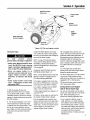 17
17
-
 18
18
-
 19
19
-
 20
20
-
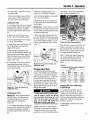 21
21
-
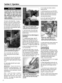 22
22
-
 23
23
-
 24
24
-
 25
25
-
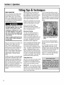 26
26
-
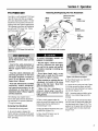 27
27
-
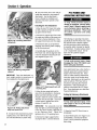 28
28
-
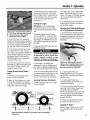 29
29
-
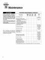 30
30
-
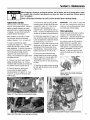 31
31
-
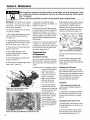 32
32
-
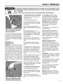 33
33
-
 34
34
-
 35
35
-
 36
36
-
 37
37
-
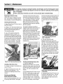 38
38
-
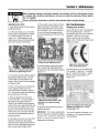 39
39
-
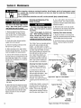 40
40
-
 41
41
-
 42
42
-
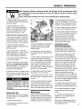 43
43
-
 44
44
-
 45
45
-
 46
46
-
 47
47
-
 48
48
-
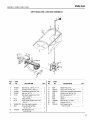 49
49
-
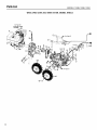 50
50
-
 51
51
-
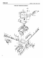 52
52
-
 53
53
-
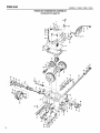 54
54
-
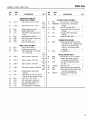 55
55
-
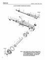 56
56
-
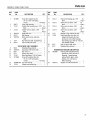 57
57
-
 58
58
-
 59
59
-
 60
60
-
 61
61
-
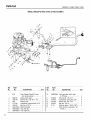 62
62
-
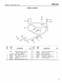 63
63
-
 64
64


Troy-Bilt 12089 Owner's manual
- Category
- Mini tillers
- Type
- Owner's manual
Ask a question and I''ll find the answer in the document
Finding information in a document is now easier with AI
Related papers
-
Troy-Bilt 12087-7HP User manual
-
-
-
-
-
-
-
Troy-Bilt E666M-Pony ES User manual
-
-
