
Zurn Industries, LLC | Specification Drainage Operation
1801 Pittsburgh Avenue, Erie, PA U.S.A. 16502 · Ph. 855-663-9876, Fax 814-454-7929
In Canada
| Zurn Industries Limited
3544 Nashua Drive, Mississauga, Ontario L4V 1L2 · Ph. 905-405-8272, Fax 905-405-1292
www.zurn.com
Z1170 (CANADIAN MARKET)
GREASE INTERCEPTOR INSTALLATION &
CLEANING INSTRUCTIONS
Rev. - Page 1 of 2
Date: 4/17/2014
C.N. No. 130831
Prod. Z1170 | Form No. IT108
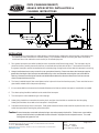
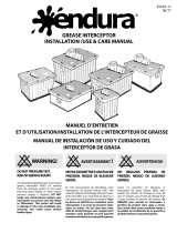
Zurn Grease Interceptors Z1170 consist of a interceptor rated at ( ) gpm and a properly sized intergal flow control.
INSTALLATION
1. When installing Zurn Interceptors use safety glasses, steel toed shoes, and gloves to prevent injuries. Interceptors must
be installed per these instructions to function properly. Any installations that do not comply with these instructions
could cause the unit to malfunction and not work per its intended purpose.
2. Zurn grease interceptors should be installed as close as possible to the fixture being served. The interceptor may be
placed on the floor, partially recessed in the floor, or recessed with top flush with the floor. The elevation of the inlet of
the grease interceptor must be located below the horizontal piping coming from the fixture that the interceptor is servicing.
3. Always install where there is easy access for cover removal and cleaning. Clearances above the interceptor must be
greater than the height of the internal removable baffle of the unit to accommodate removing the cover and baffle for
cleaning. Measure overall height of internal removable baffle to determine reference dimension of minimum access
clearance required above the unit.
4. The factory installed integral flow control plate must be in place for the unit to function properly. There must also be vent
pipes before and after the unit to prevent siphoning.
5. It is recommended that a cleanout tee be installed inbetween the fixtures and the interceptor to clear debris as needed.
6. The cleanout plug should be installed over the outlet of the interceptor.
7. The interceptor is to be installed using no-hub couplings.
8. Outlet piping should be connected to the sanitary drain, and pipe size should be no smaller than the inlet piping.
Outlet pipe should also be vented so the interceptor is not siphoned.
9. Solid waste should not go into an interceptor. Food grinder waste and other solids should be captured in the sink or by a
solids interceptor before reaching the grease interceptor.
Caution:Grease Interceptors are tested and rated using a vent and a properly sized orifice. Failure to use a vent and the
properly sized orifice that is provided with the unit will result in improper function and performance. This could
cause grease to bypass the unit.

Zurn Industries, LLC | Specification Drainage Operation
1801 Pittsburgh Avenue, Erie, PA U.S.A. 16502 · Ph. 855-663-9876, Fax 814-454-7929
In Canada
| Zurn Industries Limited
3544 Nashua Drive, Mississauga, Ontario L4V 1L2 · Ph. 905-405-8272, Fax 905-405-1292
www.zurn.com
Z1170 (CANADIAN MARKET)
GREASE INTERCEPTOR INSTALLATION &
CLEANING INSTRUCTIONS
Rev. - Page 2 of 2
Date: 4/17/2014
C.N. No. 130831
Prod. Z1170 | Form No. IT108
MAINTENANCE
General Considerations
To obtain optimum operating efficiency of a properly sized and installed grease interceptor, a regular
schedule of maintenance must be adhered to.
Note: When cleaning grease interceptors of grease be careful to wear protective gear and/ or use
a professional cleaning service to remove and dispose of the grease.
Cleaning
All grease interceptors must be cleaned regularly. The frequency of grease removal is dependent upon
the capacity of the interceptor and the quantity of grease in waste water. Check interceptor daily until a
grease level of 2" to 3" has been obtained (cleaning level). When the grease removal interval has been
determined for a specific installation, regular cleaning at that interval is necessary to maintain the rated
efficiency of the interceptor. After the accumulated grease and waste material has been removed, the
interceptor should be thoroughly checked to make certain the inlet, outlet, flow control and air relief ports
are clear of obstructions.
Please follow the steps below when cleaning.
1. Remove the center 3/8" Allen bolt lift handle assembly.
2. Remove cover, baffle and flow control.
3. Clean out remaining grease.
4. Run water into interceptor to flush. Clean out "outlet" chamber by removing cleanout plug and
spraying water down inside.
5. Clean inlet pipe of any grease or debris.
6. Inspect cover gasket and replace as needed.
7. Replace cover, baffle, and flow control. Make sure flow control is installed. Unit will not fuction
properly without it. Secure the 3/8" Allen bolt lift handle assembly.
-
 1
1
-
 2
2


Zurn Z1170-600-3IP Installation guide
- Type
- Installation guide
- This manual is also suitable for
Ask a question and I''ll find the answer in the document
Finding information in a document is now easier with AI
Related papers
-
Zurn GT2700-25-3NH Installation guide
-
-
-
-
-
-
Zurn Z1022-DU-2 Installation guide
-
-
Zurn P125-CC Installation guide
-
Other documents
-
 Wentworth WP-GT-25 Installation guide
-
 Wentworth WP-GT-10 Installation guide
-
 Wentworth WP-GT-7 Installation guide
-
 Wentworth WP-GT-50 Installation guide
-
 Wentworth WP-GT-100 Installation guide
-
 CANPLAS 3915A02CS Specification
-
CANPLAS Endura 15 User manual
-
 CANPLAS 3915A02CS User manual
-
Josam Company 58680T Installation guide
-
Ford 2016 Police Interceptor - Sedan Owner's manual


