Page is loading ...

MP-8802N page 1 of 2
Magnetic Pickup Installation Instructions
Models: MP3298, MP7905, and MP7906
MP-8802N
Revised 03-02
Section 20
(00-02-0181)
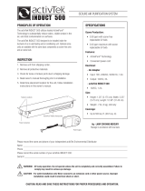
Description
A magnetic pickup is an AC generator. It is normally installed into the fly-
wheel housing of an internal combustion engine, so that the starter ring
gear acts upon it to generate a voltage pulse each time a gear tooth passes
the end of the sensor.
Specifications
Housing Material:
MP3298
: Type 300 Stainless Steel.
Locknut: Type 300 Stainless Steel.
MP7905 and MP7906
: Type 6061 Aluminum/Anodize Class 1.
Locknut: Steel Nickel Plated.
Output Leads (all models):
Two insulated leads, 20AWG, STR/TEF
insulated per MIL-W-16878D Type E, 1 White and 1 Black.
Output Voltage (all models):
200 V.P.P. TYP. (tested at 1000 I.P.S.
20 Pitch gear, 0.005 Gap., and 100K OHM Load).
Coil Resistance:
MP3298
: 975 Ohms TYP.
MP7905 and MP7906
: 2500 Ohms TYP.
Potting (all models):
Internal portion of pickup is filled with epoxy resin,
making the magnetic pickup oil and moist resistant.
Temperature (all models):
-65° to +225°F (-54 ° to 107°C).
Coil Induct.:
MP3298
: 800 mH max, @ 1K Hz.
MP3298
: 400 mH TYP. @ 1K Hz.
Pickup Part Total Threaded Thread
Model Number Length Length Size
MP3298 20700162 3 in. (76 mm) 3 in. (76 mm) 5/8-18 UNF
MP7906 20700161 3 in. (76 mm) 3 in. (76 mm) 3/4-16 UNF
MP7905 20700160 4-1/2 in. (114 mm) 4-1/2 in. (114 mm) 3/4-16 UNF
Gap Chart
Please read the following information before installing. A visual inspection of this product for damage
during shipping is recommended before mounting. These instructions are intended for MP3298, MP7905, and MP7906 models.
WARNING
BEFORE BEGINNING INSTALLATION OF THIS MURPHY PRODUCT
✔ Disconnect all electrical power to the machine.
✔ Make sure the machine cannot operate during installation.
✔ Follow all safety warnings of the machine manufacturer.
✔ Read and follow all installation instructions.
THREAD
SIZE
5/8-18 UNF
3/4-16 UNF
1/4
1/2
3/4 1
GAP
.013 in. .028 in. .035 in. .055 in.
(0.33 mm) (0.71 mm) (0.88 mm) (1.39 mm)
.015 in. .030 in. .045 in. .062 in.
(0.38 mm) (0.76 mm) (1.14 mm) (1.57 mm)
TURN
Typical Installation
Magnetic Pickup Installation (see diagram below)
Drill and tap a hole in the flywheel housing (See Specifications for
model and thread size). IMPORTANT: Drilling too deep may damage
ring gear teeth. Blow chips with air hose when drilling and tapping hole.
Gap Adjustment
Insert magnetic pickup and turn until it stops at
the face of the gear. Back-off the gear by turn-
ing the pickup counter-clockwise
1/4, 1/2, or
3/4 turn (drawing right)
.
See Gap Chart below to determine gap distance
based on the turn. Check gap clearance by
rotating the gear completely around.
NOTE: Magnetic pickup gap should be adjusted so
that the minimum voltage required is attained at the engine’s lowest
RPM. The voltage will increase as the speed increases.
If erratic readings occur, remove magnetic pickup and check the
magnetic tip for metal chips.
1/4
1/2 3/4
AC
Meter
LOAD
Tach
Speed
Switch
AC Meter
Reading must
be taken at load.
After adjusting,
set lock-nut.
Drill and tap casing
(see thread sizes in
Specifications).
Casing
Gear (must be made
of magnetic material).
NOTE: Clean gear casing
and magnetic sensor
of metal chips or filings.
Gap
(see Gap Chart)
Always use a two-conductor shielded cable. Ground the
shield to a metal frame ground at the engine end only.
Never run these wires
next to spark plug wires
or in wire loom with other
wires carrying inductive
loads or alternating current.
GENERAL INFORMATION

MP-8802N page 2 of 2
A. MP3298 and MP7906= 3 in. (76 mm)
MP7905= 4.5 in. (114 mm)
Polarity: White lead is positive with respect to
Black lead upon approach of ferrous metal.
12 in. (305 mm) min.
0.225 in.
(6 mm)
0.108
0.104 (3 mm)
B
C
A
B. MP3298= 5/8-18 UNF-2A
MP7905 and MP7906= 3/4-16 UNF-2A
C. MP3298= 0.250 in. (6 mm)
MP7905 and MP7906= 0.370 in. (9 mm)
Wire leads
0.030
0.010 (1 mm)
Note: Tested at 1000 I.P.S. 20 pitch gear
0.005 gap and 100K OHM load.
100
100 200 300 400 500 600 700 800 900 1000
Inches per Second (I.P.S.)
90
80
70
60
50
40
30
20
10
0
Voltage Output Peak to Peak
Note: Dash indicates
not recommended
Gear
Pitch
I.P.S. =
R.P.M. x dia. x 3.14
60
% Output
Std. Volts
6
8
10
12
16
20
24
32
48
64
72
187
172
162
157
118
100
85
23
–
–
–
DIMENSIONS
Output Voltage Operating Chart
Gear Pitch/Voltage Output Chart
CONTROL SYSTEMS & SERVICES DIVISION
P.O. Box 1819; Rosenberg, Texas 77471; USA
+1 281 633 4500 fax +1 281 633 4588
e-mail [email protected]
MURPHY DE MEXICO, S.A. DE C.V.
Blvd. Antonio Rocha Cordero 300, Fracción del Aguaje
San Luis Potosí, S.L.P.; México 78384
+52 444 8206264 fax +52 444 8206336
Villahermosa Office +52 993 3162117
e-mail [email protected]
www.murphymex.com.mx
FRANK W. MURPHY, LTD.
Church Rd.; Laverstock, Salisbury SP1 1QZ; U.K.
+44 1722 410055 fax +44 1722 410088
e-mail [email protected]
www.fwmurphy.co.uk
MURPHY SWITCH OF CALIFORNIA
41343 12th Street West
Palmdale, California 93551-1442; USA
+1 661 272 4700 fax +1 661 947 7570
e-mail [email protected]
www.murphyswitch.com
In order to consistently bring you the highest quality, full featured products, we reserve the right to change our specifications and designs at any time.
MACQUARRIE CORPORATION
1620 Hume Highway
Campbellfield, Vic 3061; Australia
+61 3 9358 5555 fax +61 3 9358 5558
e-mail [email protected]
FW Murphy
P.O. Box 470248
Tulsa, Oklahoma 74147 USA
+1 918 317 4100
fax +1 918 317 4266
e-mail [email protected]
www.fwmurphy.com
R
E
G
I
S
T
E
R
E
D
USA–ISO 9001:2000 FM 28221
UK–ISO 9001:2000 FM 29422
Printed in U.S.A. 078644
Warranty
A limited warranty on materials and workmanship is given with this FW Murphy product.
A copy of the warranty may be viewed or printed by going to www.fwmurphy.com/support/warranty.htm
/