ASO Safety Solutions Sentir Assembly Instructions
- Type
- Assembly Instructions

!
Montageanleitung Sicherheitskontaktmatte
Assembly Instruction Safety-Contact-Mat
richtig !
correct !
falsch !
incorrect !
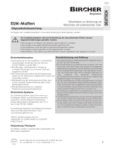
Montagehinweise
Die Montageäche muß unbedingt eben, sauber und trocken sein.
Matten dürfen nicht aufgeklebt werden.
Mit der Grundplatte nach unten die Matte auslegen
und richtig positionieren. Matten dürfen nicht geknickt
oder gebogen werden. Sicherheitskontaktmatten
dürfen in keiner Weise verändert werden. Ein Aus-
schneiden oder Kürzen ist nicht möglich.
Bei der Verlegung mehrerer Matten nebeneinander
sind diese auf Stoß zusammenzufügen. Anschlie-
ßend die Matten elektrisch verbinden und den
Widerstandswert überprüfen.
Der Widerstandswert muß bei unbetätigter Matte
8,2 kΩ ± 2% betragen.
Widerstand
8,2 kΩ
resistor
8,2 kΩ
Ω
Bei der Verlegung der Leitung im Rampen- bzw. im Befestigunsschienenkanal darauf achten, daß ein
Quetschen ausgeschlossen wird.
!
Assembly Information
The mounting surface must be absolutely even, clean and dry.
Mats may not be glued on the bottom.
Lay out and position the mat correctly with the base-
plate downwards. Mats may not be broken or bent.
Safety-Contact-Mats may not be changed in any way.
Cut outs or shortening is not possible.
The mats shall be joined end-to-end when laying
several mats together. Then connect up the mats
electrically and check the electrical resistance.
With an un-actuated mat the resistance value must
amount to 8,2 kΩ ± 2%.
During cable laying inside the ramp- and/or in the mounting rail pay attention that the cable is not
pinched.
Rampenschiene RS 14
ramp rail RS 14
Befestigungsschiene BS 14
mounting rail BS 14
Eckverbinder EVA
edge connector EVA
Kabelkanal
cable duct
Kabelkanal
cable duct
Kabelkanal
cable duct
Führungsdorn
xation-pin
Dornaufnahme
admission for pin
Für den Einsatz des Eckverbinders muß die Rampenschiene je Eckverbinder um 20mm gekürzt werden.
When using edge connectors the ramp rail must be shortened around 20mm for each edge connector.
1

Eckverbinder EVA
corner connector EVA
Rampenschiene RS 14
ramp rail RS 14
Befestigungsschiene BS 14
mounting rail BS 14
Anschlußleitung
access line
Assembly
The corner connector nearest the cable is to be mounted from obove over the cable in
such a way that the cable is guided safely into the cable duct (g. 1). Afterwards drill
and fasten it to the bottom with 6 mm dowel and suitable screw.
At the machine side the conclusion takes place via the adjustment with the mounting rail
BS 14. Fasten the rail to the bottom with 6 mm dowels and suitable screws (approx. all
60 cm). If possible bring out the cable laterally and attach it to the controler (g. 5).
Montage
Den Eckverbinder im Kabelbereich von oben so einsetzen, daß das Kabel im Kabelkanal
geführt wird (Abb. 1). Danach bohren und auf dem Untergrund mit 6 mm Dübel und
passender Schraube befestigen.
An der Maschinenseite erfolgt der Abschluß durch die Fixierung mit der Befestigungs-
schiene BS 14. Die Kabelschiene auf dem Untergrund mit 6 mm Dübeln und passenden
Schrauben befestigen (ca. alle 60 cm). Die Leitung nach Möglichkeit seitlich herausführen
und an die Auswertelektronik anschliessen (Abb. 5).
Die Rampenschienen seitlich an die Matte heranschieben und auf den Führungsdorn des Eckverbinders
stecken (Abb. 2). Die Befestigungspunkte entlang der Markierungsnut auf der Schiene kennzeichnen und für
die vorgesehenen Stopfen 10 mm vorbohren. Schienen auf dem Untergrund mit 6 mm Dübel und passenden
Schrauben befestigen (ca. alle 60 cm) und die Einschrauböffnungen mit den Stopfen verschließen (Abb.3).
Push the ramp rails laterally to the mat and then on the xation-pin of the corner connector (g. 2). Mark the
fastening points along the marking groove on the rail and pre-drill 10 mm for the intended plugs. Fasten the
rails on the bottom with 6 mm dowels and suitable screws (approx. all 60 cm) and close the openings with
the plugs (g. 3).
Weitere Eckverbinder seitlich an die Matte heranschieben und den Führungsdorn in
die Schienenaufnahme stecken (Abb. 4). Danach bohren und auf dem Untergrund mit
6 mm Dübel und passender Schraube befestigen.
Push the corner connectors laterally to the mat and then the xation-pin
into the rail (g. 4). Afterwards drill and fasten it to the bottom with 6 mm
dowel and suitable screw.
Abb.1
g.1
Abb.2
g.2
Abb.4
g.4
Abb.5
g.5
Stopfen 10mm
plug 10mm
Dübel 6mm
dowel 6mm
Markierungsnut
marking groove
Abb.3
g.3
Schraube
screw
Bohrung 10mm
drill 10mm
Montageanleitung Sicherheitskontaktmatte
Assembly Instruction Safety-Contact-Mat
1
2
2
1
2
1
c
a
.
6
0
c
m
c
a
.
6
0
c
m
2
16.DB.00.041 Technische Daten Rev 01 Stand 28.02.2008 Technische Änderungen vorbehalten
16.DB.00.041 Technical data rev 01 as of February 28th 2008 Technical changes reserved
Am Grarock 8 • D-33154 Salzkotten
www.asosafety.com • e-mail: info@asosafety.com
-
 1
1
-
 2
2


ASO Safety Solutions Sentir Assembly Instructions
- Type
- Assembly Instructions
Ask a question and I''ll find the answer in the document
Finding information in a document is now easier with AI
in other languages
- Deutsch: ASO Safety Solutions Sentir
Related papers
-
ASO Safety Solutions ELMON relay 01-27 Owner's manual
-
-
-
-
-
-
-
-
Other documents
-
 Mayser Safety Mats Installation guide
-
Biohort Woodstock T230 Assembly Instructions
-
Sport-thieme Grootvelddoel 7,32x2,44m, verschroefde verstekverbinding, verplaatsbaar User manual
-
 Duerkopp Adler 550-867 s User manual
-
 Bircher Reglomat ESM Translation Of The Original Instructions
-
Dimplex HMTS Owner's manual
-
Renkforce PAD21-04 Owner's manual
-
Chamberlain LiftMaster AGO Owner's manual
-
ROBBE Valdivia Assembly And Operating Instructions Manual
-
Auerswald COMfortel 1400 IP Setup Manual


