
WARNING: Do not use with water that is microbiologically unsafe or of unknown quality without adequate disinfection before
or after the system. The water should be tested periodically to verify that the system is performing satisfactorily.
Small parts remaining after the installation could be a choke hazard. Discard safely.
GE & PROFILE
SmartWater™ Softener Systems
INSTALLATION INSTRUCTIONS
GE Models GNSF18Z01, GNSF23Z01, GNSF35Z01 & Profile Model PNSF31Z01
TABLE OF CONTENTS: Page #
Important Installation Recommendations 1
Plan How You Will Install the Softener 2
Where to Install the Softener 2
Tools and Materials Required for Installation 2
Step-by-Step Installation Instructions
— Bypass valve 4
— Softener assembly 4
— Plumb piping 4
— Brine tank overflow fittings 4
— Valve drain hose 4, 5
— Connecting brine tank overflow hose 5
— Grounding clamps and wires 5
— Testing for water leaks 5
— Programming the control 6, 7
— Specifications/Dimensions 7
Parts List 8–11
7193812 (1-98) 215C1001P001-2 For Use and Care questions call: GE Answer Center® 800.626.2000
Pub. No. 49-5806-2 GENERAL ELECTRIC COMPANY, Appliance Park, Louisville, KY 40225
CAUTION: Certain plumbing skills are
needed for installation. If you are unsure
about any part of the installation of this
product, consult a professional plumber.
UNPACKING AND INSPECTION
The softener is shipped in one master carton.
The softener is completely assembled at the
factory, except as required at installation.
Be sure to check the entire softener for any
shipping damage or parts loss. Also note
damage to the shipping cartons. Contact the
transportation company for all damage and
loss claims. The manufacturer is not
responsible for damages in transit.
Small parts, needed to install the softener,
are on a skin-packed cardboard piece. To
avoid loss of the small parts, keep them on
the skin-pack until you are ready to use them.
1
IMPORTANT INSTALLATION RECOMMENDATIONS
Read entire manual. Failure to follow all guidelines and rules could cause personal injury or property damage.
• Follow the installation instructions carefully. Failure to properly install the softener voids the warranty.
• Before you begin installation, read these Installation Instructions completely. Then, obtain all the materials and tools you will need to
make the installation.
• Check local codes. The installation must conform to them.
• Use only lead-free solder and flux for all sweat-solder connections, as required by state and federal codes.
• Connect the softener to the main water supply pipe BEFORE or AHEAD OF the water heater. DO NOT RUN HOT WATER
THROUGH THE SOFTENER. Temperature of water passing through the softener must be less than 100° F.
• Use care when handling the softener. Do not turn upside down, drop, drag, or set on sharp protrusions.
• The softener requires a minimum water flow of 3 gallons per minute at the inlet. Maximum allowable inlet water pressure is 125 psi. If
daytime pressure is over 80 psi, nighttime pressure may exceed the maximum. Use a pressure reducing valve if necessary. (Adding a
pressure reducing valve may reduce the flow.)
• The softener works on 24 volt-60 Hz electrical power only. Be sure to use the included transformer. Be sure the electric outlet and
transformer are in an inside location to protect from wet weather.
• See “WHERE TO INSTALL THE SOFTENER” section for more details.

PLAN HOW YOU WILL INSTALL THE SOFTENER
You must first decide how to run in and out pipes to the softener. Look at the house main water pipe at the point where you will connect
the softener. Is the pipe soldered copper, glued plastic, or threaded galvanized? What is the pipe size?
WARNING: Use only lead-free solder and flux to prevent lead poisoning.
Look at Fig. 1 for models GNSF18, GNSF23 and GNSF35 or Fig. 2 for model PNSF31. Use this as a guide when planning your particular
installation. Be sure to direct the incoming hard water supply to the softener valve inlet fitting. The valve is marked IN and OUT. See
below to help you prepare.
NOTE: The state of Massachusetts requires a licensed plumber to perform the installation.
2
•In and out pipes to the softener must be at least 3/4″size. Some
local codes require a minimum of 1″pipe size. To plumb with 1″
pipes, buy adapters to fit the 1″pipe threads on the bypass valve
(see Figures 1 and 2).
• Use copper, brass or galvanized pipe and fittings. Some codes
may also allow CPVC plastic pipes.
•Use the included bypass valve to install the softener. The bypass
valve allows you to turn off water to the softener for servicing, but
still have water in the house pipes.
•Drain hose is needed for valve and salt tank drains. A 20′ length
of drain tubing is included. If a longer length is needed, it can be
ordered from GE Parts at 800.626.2002.
• If a rigid valve drain is needed to comply with plumbing codes,
you can buy the parts needed (Fig. 4A) to connect a 1/2″copper
tubing or plastic pipe drain.
• Clean nugget or pellet water softener salt is needed to fill the
brine tank, see step 9.
TOOLS AND MATERIALS REQUIRED FOR INSTALLATION
• Place the softener as close as possible to a sewer drain, or other
acceptable drain point or standpipe.
• It is recommended to keep outside faucets on hard water to save
soft water and salt.
• Do not install the softener in a place where it could freeze. Freeze
damage is not covered by the warranty.
• Do not install the softener where it would block access to the
water heater or access to the main water shutoff.
• Put the softener in a place where water damage is least likely to
occur if a leak develops. The manufacturer will not repair or pay
for water damage.
• A 120 volt electric outlet is needed to plug in the included
transformer. The softener has a 10 foot power cable. If the outlet
is remote (up to 100 feet), use 18 gauge wire to connect. Be sure
the electric outlet and transformer are in an inside location, to
protect from wet weather. Be sure the outlet is unswitched to
prevent accidental shutoff.
• If installing in an outside location, you must take the steps
necessary to assure the softener, installation plumbing, wiring,
etc., are as well protected from the elements (sunlight, rain,
wind, heat, cold), contamination, vandalism, etc., as when
installed indoors.
• Keep the softener out of direct sunlight. The sun’s heat may
distort non-metallic parts and may damage the electronics.
WHERE TO INSTALL THE SOFTENER

TYPICAL INSTALLATION ILLUSTRATION
3
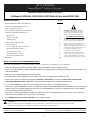
Fig. 1
OPTIONAL 3-VALVE BYPASS INSTALLATION ILLUSTRATION
Adapters for this installation are not supplied with the softener.
Fig. 2
Soft water
Hard water to
outside faucets
MAIN WATER PIPE
Hard water
Installation nut (2)
Copper tube, 3/4″ (2)
Washer (2)
Bypass Valve
•Pull out for service
•Push in for bypass
NOTE: Threads on the bypass
valve are 1″ male pipe. If 1″ pipes
are needed, do not use the
copper tubes and nuts included.
Buy adapters and plumb directly
to the 1″threads.
INLET
Brinewell
Note: See drain hose
connections, page 6.
SALT
GOES HERE
Salt hole
cover
removed
24V transformer
120-volt outlet
Hard water
Soft water
From softener
outlet
To softener
inlet
CROSS-OVER
Use if water supply flows from
the left. Include single or
3-valve bypass.
CROSS-OVER
Use if water supply flows from
the left. Include single or
3–valve bypass.
To softener
inlet
From softener
outlet
Hard water
Soft water
MAIN WATER PIPE
Soft water
Hard water
Copper tube, 3/4″ (2)
Washer (2)
Installation adapter (2)
INLET
NOTE: Threads on the installation adapters are
1″ male pipe. If 1″ pipes are needed, do not use
the copper tubes and nuts included. Buy adapters
and plumb directly to the 1″threads.
24V transformer
120-volt outlet
Bypass valve
Hard water to
outside faucets
Inlet valve
Outlet valve
Nut (2)
For soft water service:
- Open the inlet and outlet valves
- Close the bypass valve
For bypass hard water:
- Close the inlet and outlet valves
- Open the bypass valve
3-valve bypass system

Turn off the water supply to pipes to be cut and drain the house water pipes. Open both
hot and cold faucets.
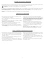
1. INSTALL BYPASS VALVE
•Remove plastic shipping plug and wire from valve outlet.
• Push the bypass valve (lubricate o-ring seals with silicone grease) into both ports of the
valve as shown in Fig. 3A.
• Snap the 2 large plastic clips in place, from the top, down as shown in Figures 3A and 3B.
Be sure they snap into place. Pull on the bypass valve to make sure it is held securely in
place.
2. MOVE THE SOFTENER ASSEMBLY INTO INSTALLATION POSITION:
•Be sure the installation surface is level and smooth. Sharp objects under the tank may
puncture it. If needed, place the tank on a section of 3/4″thick (minimum) plywood.
Then, place shims under the plywood as needed to level the softener.
3. PLUMB IN AND OUT PIPES TO AND FROM SOFTENER:
CAUTION: Observe all of the following cautions as you connect inlet and outlet
plumbing.
• BE SURE INCOMING HARD WATER SUPPLY IS DIRECTED TO THE SOFTENER
VALVE INLET PORT. If house water flow is from the left, use a plumbing cross-over as
shown in Fig. 1.
• If making a soldered copper installation, do all sweat soldering before connecting pipes
to the bypass valve. Torch heat will damage plastic parts.
• When turning threaded pipe fittings onto plastic fittings, use care not to cross-thread.
• Use pipe joint compound on all external pipe threads.
• Support inlet and outlet plumbing in some manner (use pipe hangers) to keep the
weight off of the valve fittings.
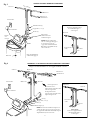
4. INSTALL THE BRINE TANK OVERFLOW FITTINGS:
• Insert the rubber grommet into the 3/4″diameter hole in the brine tank sidewall as
shown in Fig. 5.
• Push the end of the hose adapter elbow into the grommet as shown in Fig. 5.
5. CONNECT AND RUN THE VALVE DRAIN HOSE:
• Use the provided drain hose (20′length included) to attach to the valve drain fitting.
To keep water pressure from blowing the hose off, use a hose clamp to secure in place.
• Locate the other end of the hose at a suitable drain point (floor drain, sump, laundry
tub, etc.) that terminates at the sewer. Check and comply with local codes.
IMPORTANT: If more drain hose is needed, it can be ordered from GE Parts at
800.626.2002. The water softener will not work if water cannot exit this hose during
regenerations.
• Tie or wire the hose in place at the drain point. High water pressure will cause it to whip
during the back-wash and fast rinse cycles of regeneration. Also provide an air gap of at
least 1–1/2″between the end of the hose and the drain point. An air gap prevents
possible siphoning of sewer water into the softener, if the sewer should “back-up.”
• If raising the drain hose overhead is required to get to the drain point, do not raise
higher than 8′above the floor. Elevating the hose may cause a back-pressure that could
reduce brine draw during regenerations.
Fig. 3A.
Fig. 3B.
Fig. 3C.
Fig. 4.
STEP-BY-STEP INSTALLATION INSTRUCTIONS
NOTE: Be sure the turbine
and support are firmly in
place in the valve outlet.
Blow into the valve port and
observe the turbine
for free rotation.
4
Drain
fitting
on
valve
Valve
drain
hose
To sewer drain
Turbine
Valve outlet
Turbine shaft
and support
IN
OUT
Turn bypass valve
up-side down to
connect to floor
level plumbing
Valve body
inlet or outlet
Bypass valve
(push all the way in)
Clip
END
VIEW
Clip
Outlet
Inlet
O-ring seal goes into the outer
groove only. The clip snaps into
the inner groove (see below).
Bypass valve
NOTE: Threads
on the valve are 1″
male pipe. If 1″
pipe is needed,
buy adapters and
plumb to the 1″
threads.
SIDE
VIEW

5A. CONNECTING A RIGID VALVE DRAIN TUBE
• To adapt a copper drain tube to the softener, use a hacksaw to cut the barbed end from
the drain fitting as shown in Fig. 4A. Rotate the drain fitting so the cutting blade clears
the valve housing to prevent damage to valve. Buy a compression fitting (1/4″female
pipe thread x 1/2″O.D. tube) and needed tubing from your local hardware store.
6. CONNECT AND RUN THE CABINET (BRINE TANK) OVERFLOW HOSE
•Attach a length of hose (use remaining hose from step 5) to the drain elbow installed
in step 4. Use a hose clamp to hold it in place.
• Locate the other end of the hose at the drain point. DO NOT ELEVATE this hose
higher than the elbow on the brine tank. DO NOT TEE this hose to the valve drain
hose.
NOTE: This drain is for safety only. If the cabinet (brine tank) should over-fill with
water, the excess is carried to the drain.
7. INSTALL GROUNDING CLAMPS AND WIRE
DANGER: Failure to properly attach ground wire could result in electrical shock.
• If plumbing is metal, to maintain electrical ground continuity in the house cold water
piping, install the included ground clamps as shown in Fig. 6. Be sure the pipes are
clean under the clamps to assure good contact.
8. FLUSH PIPES, EXPEL AIR FROM SOFTENER, AND TEST YOUR
INSTALLATION FOR WATER LEAKS:
CAUTION: To avoid water or air pressure damage to softener inner parts, be
sure to do the following steps in exact order.
A. Fully open 2 cold soft water faucets nearby the softener.
B. Place bypass valve in “bypass” position by pushing the stem inward.
C. Fully open the house main water pipe shutoff valve. Observe a steady flow from both
faucets opened in step A, above.
D. Place bypass valve in the “service” position EXACTLY as follows. KEEP SOFT
WATER FAUCETS OPEN.
SLOWLY pull or slide the valve stem toward “service,” pausing several times to
allow the softener to pressurize slowly.
E. After about 3 minutes, open a HOT water faucet for 1 minute, or until all air is
expelled, then close.
F. Close all water faucets.
G. Check your plumbing work for leaks and fix right away if any are found. Be sure
to observe previous caution notes.
H. Turn on the gas or electric supply to the water heater. Light the pilot, if applicable.
Fig. 4A
Fig. 5
Fig. 6
9. ADD WATER AND SALT TO THE BRINE TANK:
•Lift the cabinet (brine tank) cover. Add about 3 gallons of water into the tank. Do not add into the brinewell.
• Fill tank with NUGGET, PELLET or coarse SOLAR water softener salt with a purity of 99.5% or higher. Do not use rock, block,
granulated, and ice cream-making salts, or salt with iron-removing additives. Also see the Owner’s Manual. Salt storage capacity is
approximately 150 lbs. for model GNSF18 and 200 lbs. or more for the other models.
NOTE: If the softener is installed in a humid basement or other damp area, it is better to fill the tank with less salt, more frequently.
Eighty to 100 lbs. of salt will last for several months, depending on water hardness, family size and water softening system model .
10. CONNECT TO ELECTRICAL POWER:
•If transformer wiring is not visible at the back of the control head, remove control cover. DO NOT PULL ON OR DISCONNECT
WIRING. Locate the long wire with “U” shaped connectors on one end. Route this wire through the rear of the control housing.
Replace the control cover.
• Fasten the 2 power cable lugs (“U” shaped connectors) to the 2 screws on the transformer, and tighten the screws. Then, plug the
transformer into the electrical outlet.
11. PROGRAM THE CONTROL:
•See Programming the Control section.
5
Clamp (2)
Ground
wire
From valve outlet
To valve inlet
To sewer drain
Overflow drain hose
Hose clamp
Grommet
Clip
1/4″NPT threads
Barbs
1/2″O.D.
copper tube
(not furnished)
Cut barbs
from drain
fitting
Compression fitting,
1/4″NPT X 1/2″ O.D.
tube (not furnished)

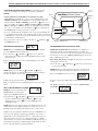
SET PRESENT TIME OF DAY
NOTE: If the words PRESENT TIME do not show in the display,
press the SELECT button until they do.
1. Press the UP (+) or DOWN (-) button to set. The UP
button moves the display ahead; the DOWN button moves the
time backward.
If the present time is between noon and midnight, be sure PM
shows.
NOTE: Each press of an UP (+) or DOWN (-) button
changes the time by one minute. Holding the button in changes
the time 32 minutes each second.
2. When the present time shows, press SELECT to set.
If the present time is between midnight and noon, be sure AM
shows.
SET WATER HARDNESS NUMBER
NOTE: If 15 (factory default) and
HARDNESS do not show in the
display, press SELECT until they do.
1. Press the UP (+) or DOWN (-) button to set your water
hardness number in the display. DOWN (-) moves the
display down to 1. UP (+) moves the
maximum setting.
NOTE: Each press of a button changes the display by 1 between 1
and 25. Above 25, the display changes 5 at a time (25, 30, 35, etc.).
Holding a button in changes the numbers twice each second.
2. When your water hardness number shows, press SELECT to set.
You can get the grains per gallon (gpg) hardness of your water
supply from a water analysis laboratory, or call and ask your local
water department, if you are on a municipal supply, or call GE
Answer Center® to request a water hardness test kit. If your report
shows hardness in parts per million (ppm) simply divide by 17.1 to
get the eqivalent number of grains per gallon.
SET REGENERATION (STARTING) TIME
NOTE: RECHARGE TIME and a flashing 2:00 AM (factory
default) should show in the display. This is a good time for
regeneration to start (over in about 2 hours) in most households
because water is not is use. HARD WATER is bypassed to house
faucets during regeneration.
If no change is needed, go to step 2. To change the regeneration
starting time, follow step 1.
1. Press the UP
(+)
or DOWN (-) button to set the desired
regeneration start time.
NOTE: Each press of the buttons changes the time by 1 hour.
Holding the buttons in changes the time twice each second.
2. Press the SELECT button once more.
Be sure to observe the AM or PM, as you did when setting the time
of day.
The display shows the present time of day and RECHARGE
TONIGHT.
See the Owner’s Manual for further details.
HARDNESS
PRESENT TIME
AM
•CONTROL SETTINGS REQUIRED upon installation and
after an extended power outage (see the Owner’s Manual).
NOTES:
•
WHEN THE TRANSFORMER IS PLUGGED INTO THE
ELECTRICAL OUTLET (see step 10), 12:00 AM (flashing), and
PRESENT TIME show in the display area. Program the control as
instructed below. If SR - - is flashing, use the UP (+) button to set
the correct SR code as follows: SR18 for GNSF18, SR17 for GNSF23,
SR35 for GNSF35, or SR22 for Profile model PNSF31. If you pass by
the correct code number, use the DOWN (-) button. Then press
the SELECT button and program the control.
•
A “beep” sounds while pressing buttons for control programming.
One
beep signals a change in the control display. Repeated beeps means the
control will not accept a change from the button you have pressed, and
you should use another button.
•To program the control, you will use the UP (+) , DOWN (-)
and SELECT buttons.
PROGRAMMING THE CONTROL FOR GE MODELS GNSF18, GNSF23, GNSF35 AND PROFILE MODEL PNSF31
SmartWater Softener System
TOUCH
or
HOLD
SELECT
TIME
HARDNESS
RECHARGE NOW
RECHARGE TONIGHT
Display
TOUCH or HOLD button
SELECT button
DOWN (-)
button
UP (+)
button
PRESENT TIME
PM
PRESENT TIME
PM
RECHARGE
AM
TIME
6
display up to the

TO COMPLETE THE INSTALLATION—Carry out the following sanitizing procedures before salt is added to the softener
Care is taken at the factory to keep your water softener clean and
sanitary. Materials used to make the softener will not infect or
contaminate your water supply, and will not cause bacteria to form
or grow. However, during shipping, storage, installing and
operating, bacteria could get into the softener. For this reason,
sanitizing as follows is suggested when installing.
NOTE: Sanitizing is recommended by the Water Quality
Association for disinfecting.
1. Be sure to complete all installation steps, including control
programming.
2. Mix about 3/4 oz. of common 5.25% household bleach (Clorox,
Linco, Bo Peep, White Sail, Eagle, etc.) with about 1 quart of
water and pour this mixture into the brinewell. It is important
not to pour undiluted bleach into the softener.
3. IMPORTANT: Press and hold (for 3 seconds) the TOUCH or
HOLD button to start an immediate regeneration. RECHARGE
NOW begins to flash in the display. The bleach is drawn into
and through the water softener to sanitize it. This sanitizing
regeneration is over in about 2 hours. Then, soft water is
available for your use.
NOTE: When the above sanitizing regeneration is over, your house
COLD water supply is fully soft immediately. However, your water
heater is filled with hard water and, as hot water is used, it will refill
with soft water. When all the hard water is replaced in the water
heater, hot only and mixed hot and cold water will be fully soft. If
you want totally soft water immediately, after the above
regeneration, drain the water heater until the water runs cold.
DANGER: If you do drain the water heater, use extreme care
as the hot water could cause burns.
SPECIFICATIONS/DIMENSIONS
Rated Capacity
Amount of high capacity resin (lbs/cu. ft)
Resin tank nominal size (in., dia. x height)
Service flow rate (gpm)
Water supply maximum hardness (gpg)
➄
Water supply maximum clear water iron (ppm) ➄
Water pressure limits (min.-max. psi)
Pressure drop at rated service flow (psig)
Water temperature maximum (°F)
Water supply minimum flow rate (gpm)
Regeneration cycle flow rates (gpm)
Fill (flow to brine tank)
Brining
Brine Rinse
Backwash
Fast Rinse
GNSF18
38/.73
10 x 21
7
25
3
20-125
15
120
3
.3
.24
.14
1.8
1.8
GNSF23
31.2/.6
8 x 40
8
50
3
20-125
15
120
3
.3
.19
.12
1.8
1.8
GNSF35
48.4/.93
9 x 40
10
100
6
20-125
15
120
3
.3
.20
.16
2.0
2.0
PNSF31
41.6/.8
10 x 35
10
95
5
20-125
15
120
3
.3
.19
.12
2.3
2.3
See rating decal, located on the Softener
➄Determined by water analysis from a qualified water testing laboratory.
}
(flow to drain)
7
GNSF18
11–1/2″
INLET-OUTLET
29–3/4″
22–1/4″
20–1/4″
21–1/2″
3–3/8″
INLET
OUT
GNSF23 &
GNSF35
PNSF31
11–1/2″ 11–1/2″
3–3/8″
3–3/8″
OUT
OUT
INLET
INLET
INLET-OUTLET
INLET-OUTLET
48–3/4″
41–1/4″
18–1/4″
40–1/2″
44″
36–1/4″
14″
35″
24″

8

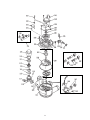
GENERAL ELECTRIC PARTS CATALOG
REF. NO. PART NO. PART DESCRIPTION
0003 WS35X10001 O-RING SEAL KIT 1 1 1 1
0004 WS34X10003 DECAL - - - -
WS34X10002 DECAL - 1 - -
WS34X10001 DECAL 1 - 1 1
0005 WS07X10004 HOSE DRAIN, 20 FT. 1 1 1 1
0007 WS14X10002 DISTRIBUTOR TOP 1 1 1 1
0008 WS14X10001 DISTRIBUTOR BOTTOM 1 1 1 1
0009 WS01X10002 RESIN - 1 CU. FT. 1 1 1 1
0010 WS32X10001 TANK RESIN 1 - - -
WS32X10004 TANK RESIN - 1 - -
TANK RESIN - - 1 1
TANK RESIN - - 1 -
0011 WS31X10001 COVER BOTTOM 1 1 1 1
0012 WS31X10002 COVER CONTROL 1 1 1 1
WS31X10008 COVER CONTROL - - - -
0013 WS21X10004 CONTROL - - - -
WS21X10002 CONTROL 1 1 1 1
0014 WS19X10003 HARNESS WIRE 1 1 1 1
0015 WS06X10003 POWER CORD 1 1 1 1
0016 WS26X10001 TRANSFORMER 1 1 1 1
0017 WS31X10010 COVER SALT HOLE 1 1 1 1
0018 WS33X10001 SEAL VAPOR BARRIER 1 - 1 1
WS33X10003 SEAL VAPOR BARRIER - 1 - -
0019 WS33X10002 RIM 1 1 1 1
0020 WS31X10011 COVER BRINEWELL - 1 - -
WS31X10003 COVER BRINEWELL 1 - 1 1
0021 WS02X10009 WING NUT, 1/4 ″ - 20 1 1 1 1
0022 WS32X10002 TANK BRINEWELL, ROUND 1 1 1 1
0023 WS02X10011 SCREW, 1/4 ″ - 20 NYLON 1 1 1 1
0024 WS32X10005 TANK BRINE, RECTANGULAR - 1 - -
WS32X10003 TANK BRINE, ROUND 1 - 1 1
0025 WS18X10003 CLAMP HOSE 1 1 1 1
0026 WS22X10016 ADAPTER HOSE 1 1 1 1
0027 WS22X10017 GROMMET 1 1 1 1
0028 WS35X10002 GROUND CLAMP KIT 1 1 1 1
0029 WS15X10005 BRINE VALVE ASM. 1 1 1 1
0030 WS35X10003 FLOAT, STEM & GUIDE ASM. 1 1 1 1
0031 WS03X10006 CLIP 1 1 1 1
0032 WS15X10006 VALVE BODY, BRINE 1 1 1 1
0033 WS03X10007 CLIP 1 1 1 1
0034 WS03X10008 SCREEN 1 1 1 1
0035 WS07X10002 TUBING ASM. 1 1 1 1
0036 WS07X10003 TUBE BRINE 1 1 1 1
0037 WS31X10004 COVER REAR 1 1 1 1
0038 WS31X10005 COVER SALT FILL 1 1 1 1
0055 WS28X10003 RETAINER CLAMP 2 2 2 2
0056 WS28X10004 CLAMP 2 2 2 2
0999 49-5799 PM MANUAL USE & CARE 1 - 1 1
49-5806 PM INSTRUCTION INSTALL 1 1 1 1
49-5805 PM INSTRUCTION INSTALL - - - -
49-5800 PM MANUAL USE & CARE - 1 - -
49-5801 PM MANUAL USE & CARE - - - -
G P G G
N N N N
S S S S
F F F F
2 3 1 3
3 1 8 5
Z Z Z Z
0 0 0 0
1 1 1 1
9

10

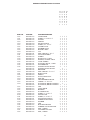
GENERAL ELECTRIC PARTS CATALOG
REF. NO. PART NO. PART DESCRIPTION
0025 WS18X10003 CLAMP HOSE 1 1 1 1
0101 WS02X10012 SCREW, #4 - 24 X 1-1/8² 1 1 1 1
0102 WS02X10013 SPACER 1 1 1 1
0103 WS21X10003 SWITCH 1 1 1 1
0104 WS03X10009 PIN EXPANSION 1 1 1 1
0105 WS02X10014 SCREW, #10 - 14 X 2² 5 5 5 5
0106 WS31X10006 COVER VALVE 1 1 1 1
0107 WS03X10010 WASHER WAVE 1 1 1 1
0108 WS26X10002 ROTOR & DISC 1 1 1 1
0109 WS19X10004 CAP 1 1 1 1
0110 WS03X10011 SEAL O-RING 1.1² X 1.4² 1 1 1 1
0111 WS19X10005 SUPPORT SCREEN 1 1 1 1
0112 WS03X10013 SCREEN 1 1 1 1
0113 WS22X10020 FLOW PLUG, .1 GPM 1 - 1 1
0114 WS08X10005 GASKET, NOZZLE/VENT 1 1 1 1
0115 WS03X10015 CONE SCREEN 1 1 1 1
0116 WS22X10021 PLUG, FILL FLOW, .3 GPM 1 1 1 1
0117 WS03X10017 NUT FERRULE 1 1 1 1
0118 WS15X10009 NOZZLE/VENTURI ASM. 1 - 1 1
WS15X10017 NOZZLE/VENTURI ASM. - 1 - -
0119 WS03X10018 RETAINER 1 1 1 1
0120 WS03X10019 SEAL O-RING 1/4² X 3/8² 2 2 2 2
0121 WS15X10010 BODY VALVE 1 1 1 1
0122 WS03X10020 SPRING 1 1 1 1
0123 WS22X10022 PLUG, DRAIN SALT 1 1 1 1
0130 WS35X10005 SEAL KIT 1 1 1 1
0132 WS22X10023 ADAPTER DRAIN HOSE 1 1 1 1
0133 WS03X10021 O-RING 5/8² X 13/16² 1 1 1 1
0134 WS03X10031 PLUG FLOW, RINSE CONTROL - 1 - -
WS03X10022 PLUG FLOW, RINSE CONTROL 1 - 1 1
0135 WS03X10023 CLIP 1 1 1 1
0136 WS26X10003 CAM & GEAR 1 1 1 1
0137 WS26X10004 BEARING 1 1 1 1
0138 WS26X10005 PLATE MOTOR 1 1 1 1
0139 WS02X10015 SCREW, #6 - 20 X 3/8² 2 2 2 2
0140 WS26X10006 MOTOR ASM. 1 1 1 1
0141 WS02X10016 SCREW, #6 - 20 X 7/8² 2 2 2 2
0142 WS60X10001 NUT INSTALLATION 2 2 2 2
0143 WS60X10002 TUBE INSTALLATION 2 2 2 2
0144 WS60X10003 WASHER 2 2 2 2
0145 WS60X10004 CLIP 2 2 2 2
0146 WS28X10005 HOUSING SENSOR 1 1 1 1
0147 WS19X10006 TURBINE & SUPPORT ASM. 1 1 1 1
0150 WS03X10024 SEAL, O-RING 1 1 1 1
0151 WS15X10012 VALVE BYPASS ASM. 1 1 1 1
0152 WS03X10025 SEAL, O-RING 2 2 2 2
11
G P G G
N N N N
S S S S
F F F F
2 3 1 3
3 1 8 5
Z Z Z Z
0 0 0 0
1 1 1 1

12
-
 1
1
-
 2
2
-
 3
3
-
 4
4
-
 5
5
-
 6
6
-
 7
7
-
 8
8
-
 9
9
-
 10
10
-
 11
11
-
 12
12


GE PNSF31Z Installation guide
- Type
- Installation guide
- This manual is also suitable for
Ask a question and I''ll find the answer in the document
Finding information in a document is now easier with AI
Related papers
Other documents
-
Kenmore IntelliSoft 370 Series User manual
-
-
-
-
-
-
-
Jones Stephens D59130 Installation guide
-
-
Kenmore Elite Elite INTELLISOFT 420 SERIES 625.38426 Owner's manual