
0740 800 152 061012
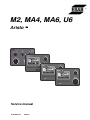
M2,MA4,MA6,U6
Aristo
t
Service manual

S0740 800 152/E061012/P36
-- 2 --TOCe
Rights reserved to alter specifications without notice.
READ THIS FIRST 3.................................................................
INTRODUCTION 3...................................................................
DESCRIPTION OF OPERATION 4.....................................................
1AP1 Welding data board 4........................................................
1AP1:1 Power supply 4...........................................................
1AP1:2 Communication 5.........................................................
1AP1:3 Fault indication, panel M2 5................................................
1AP1:4 Settings, panel M2 5......................................................
1AP1:5 Display, panels MA4, MA6 and U6 6........................................
1AP1:6 Settings, panels MA4, MA6 and U6 6........................................
1AP1 Component positions 7....................................................
F AULT CODES 8....................................................................
Fault log 8........................................................................
Fault indication on the M2 control panel 8..........................................
Fault codes for the MA4, MA6 and U6 panels 9......................................
Summary of fault codes 9.........................................................
Fault code descriptions, control panel 10............................................
SERVICE INSTRUCTIONS 12..........................................................
What is ESD? 12...................................................................
Service aid 13......................................................................
Exchange circuit boards 14.........................................................
INSTRUCTIONS M2 15................................................................
INSTRUCTIONS MA4 16...............................................................
INTRODUCTION 16.................................................................
MENUS 17.........................................................................
MIG/MAG WELDING 18.............................................................
MMA WELDING 20.................................................................
INSTRUCTIONS MA6 and U6 22.......................................................
INTRODUCTION 22.................................................................
MENUS 23.........................................................................
Menu structure, panel MA6 24......................................................
Menu structure, panel U6 25........................................................
MIG/MAG WELDING 26.............................................................
TIG WELDING, panel U6 30.........................................................
MMA WELDING 33.................................................................
ARC --AIR GOUGING 33.............................................................
GENERAL FUNCTIONS 33..........................................................
Remote control unit 33.............................................................
Settings 34........................................................................
MEMORY MANAGEMENT 34........................................................
LOCK CODE 34
....................................................................
SPARE PARTS 35....................................................................
NOTES 35...........................................................................

S0740 800 152/E061012/P36
-- 3 --
ci01d1
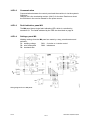
READ THIS FIRST
Maintenance and repair work should be performed by an experienced person, and
electrical work only by a trained electrician. Use only recommended replacement parts.
This service manual is intended for use by technicians with electrical/electronic training for
help in connection with fault--tracing and repair.
This manual contains details of design changes that have been made up to and including
September 2006.
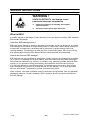
WARNING !
STATIC ELECTRICITY can damage circuit
boards and electronic components.
S Observe precautions for handling electrostatic--
sensitive devices.
S Use proper static--proof bags and boxes.
ESD
INTRODUCTION
The MMC module consists of a control panel and a welding data board.
The power source, the wire feed unit and control panel each have their own microprocessor
for control. The control panel is the central unit in the system: in addition to setting and
controlling welding data, it also has overall control of the entire system.
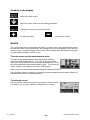
The M2 panel, with knobs for all settings. See page 15 for a description
of operation. The function description below refers to various fault codes.
However, the M2 panel indicates faults by means of an LED, which can
either flash or light steadily to indicate a fault. The fault indication function
is described in the section on FAULT CODES: see Page 8.
The MA4 panel, with knobs for setting welding voltage and wire feed
speed / current. Other settings are controlled by pushbuttons and
symbols in the display panel. See page 16 for a description of operation.
The MA6 and U6 panels, with knobs for setting welding voltage and wire
feed speed / current. Other settings are controlled by pushbuttons and
text in the display panel. See page 22 for a description of operation.

S0740 800 152/E061012/P36
-- 4 --
ci01d1
DESCRIPTION OF OPERATION
1AP1 Welding data board
The hardware of the printed circuit board is the same for the MA4, MA6 and U6 panels. For
the M2 panel the same board is used, but there are some differences in the hardware.
Circuit board identity
The welding data board has a machine ID, a hardware ID and a unit type number. To read
this you need the ESAT service kit, see page 13.
S The machine ID defines which type of control panel the board is intended for. If the
board is to be used for another type of control panel, the machine ID can be changed
by ESAT. Spare part boards can be delivered with or without machine ID, see page 14.
S The hardware ID shows design and type of circuit board.
S The unit type is used for identification on the CAN bus.
The ID numbers of the control panels are:
M2 machine ID = 4
MA4 machine ID = 7
MA6 machine ID = 9
U6 machine ID = 10
Hardware ID = 1
Unit type = 0
1AP1:1 Power supply
Circuit board 1AP1 receives a 12 V power supply from the control board in the
power source. This is regulated to 5 V, which supplies all the circuits in the
control panel. The 12 V and 5 V supplies are monitored by a reset circuit:
tolerance values are 12 V +2/-- 3 V and 5 V ±0.25 V. Monitoring the voltages
makes sure that, in the event of loss of power, the processor has time to save
the current data to RAM and to shut down the current processes in a controlled
manner.
Loss of power supply does not generate a fault code. If the 12 V supply drops
below 9 V, either momentarily or indefinitely, but does not fail entirely, the
background lighting to the display will go out, followed by display of fault code
4. The machine must be turned off, and then on again, to reset the system.
The RAM memory requires a power supply even when the machine is turned
off. This is provided by battery BA1, see the component positions on page 7.
The battery is connected by the reset circuit when the mains power supply is
turned off or lost. The battery voltage is monitore d by the processor: fault code
8 is displayed if it drops below 2.4 V.
Replacing the battery
The battery is soldered to the circuit board. Removing it causes the RAM
memory to lose all stored data, e.g. the machine’s fault log. When the new
battery has been fitted, and the machine restarted, the panel will be in its
default state, i.e. as it originally left the factory.
It is possible to prevent data from being lost if a 12 V supply is maintained to
the board while the battery is being changed.
Warning: the circuit board is sensitive to ESD.

S0740 800 152/E061012/P36
-- 5 --
ci01d1
1AP1:2 Commu n ication
Communication between the control panel and the machine is via the system’s
CAN bus.
Resistor R3 is the terminating resistor (120 Ù) for the bus. Read more about
the CAN bus in the service manual for the power source.
1AP1:3 Fault indication, panel M2
The M2 panel has a single fault-- indicating LED, which is controlled by
transistor Q1. The faults indicated by the LED are described on page 8.
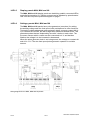
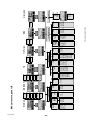
1AP1:4 Settings, panel M2
Welding settings from the M2 panel are made by rotary potentiometers and
switches:
R1: welding voltage SW1: 2--stroke or 4-- stroke control
R2: wire feed speed SW2: inductance
R3: burnback time
Wiring diagram for the M2 panel.

S0740 800 152/E061012/P36
-- 6 --
ci01d1
1AP1:5 Display, panels MA4, MA6 and U6
The MA4, MA6 and U6 display panels are backlit by parallel --connected LEDs,
controlled by transistor Q1. Display contrast can be adjusted b y potentiometer
R52: see the component positions diagram on page 7.
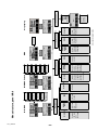
1AP1:6 Settings, panels MA4, MA6 an d U6
The MA4, MA6 and U6 panels have pulse generators (encoders) for setting
the welding voltage and wire feed speed, with pushbuttons for other functions.
Turnin g the voltage adjustment pulse generator briefly connects contact A3 (0
V) to contacts A1 and A2, but with a slight time difference between them. This
generates pulses that are displaced by about 90° relative to each other. The
processor senses which contact was first connected to 0 V, and decides
whether the voltage is to be increased or decreased.
When the pulse generator knob is not being turned, the voltage on contacts A1
and A2 is +5 V. The wire feed speed pulse generator operates in a similar
manner.
Wiring diagram for the MA4, MA6 and U6 panels.

S0740 800 152/E061012/P36
-- 7 --
ci01d1
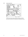
1AP1 Component positions
The printed circuit board is the same, regardless of which type of panel it is
used for. The picture above shows all the components with which the board
may b e fitted: the exact choice of components varies, depending on the panel.

S0740 800 152/E061012/P36
-- 8 --
ci01f1
FAULT CODES
Fault log
All faults that occur when using the welding equipment are documented as error messages
in the fault log: up to 99 error messages can be saved. When 99 messages have been
saved, the oldest message will automatically erase when the next fault occurs.
Only the most recent fault message is displayed on the control panel. To read the entire
fault log, the machine must be connected to the ESAT: see service aid o n page 13.
Faults are monitored/detected in two ways: by test routines that are run on initiation and by
functions that can detect a fault when it occurs.
The control panel displays a unit number to indicate which unit has generated the fault.
Fault indication on the M2 control panel
The M2 control panel has no text or symbol display, and so faults are indicated by an LED.
The LED is extinguished if there are no faults, but either flashes or lights steadily to indicate
a fault. See the specification of fault codes on page 10 for a detailed description of the
various fault codes.
The LED flashes for the following faults:
Fault
code
Description
17
The control panel has lost contact with the wire feed unit
.
18 The control panel has lost contact with the control board in the power source.
27 Outofwire.
29 No cooling water flow .
32 No gas flow.
The LED lights continuously for other faults.
The LED lights / flashes as long as the fault is present, it can only be reset if the fault is
repaired and the machine is restarted.

S0740 800 152/E061012/P36
-- 9 --
ci01f1
Fault codes for the MA4, MA6 and U6 panels
Fault codes are updated every three seconds. They are shown on the display in the form of
a symbol, as follows:
The upper figure in the symbol is the number of the particular fault code. The
lower figure indicates where the fault is:
0 = control panel 1 = cooling unit 2 = power source
3 = wire feed unit 4 = remote control unit
The above symbol show that the control panel (0) has lost contact with the power source.
Symbols may be steady or flashing, depending on the type of fault. Flashing symbols are
indicaded with “o” in the table below.
If several faults have been detected, the code of only the most recent fault is displayed.
Press any of the function keys in order to clear the symbol from the display.
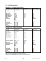
Summary of fault codes
Fault
code
Description Control
panel
Cooling
unit
Power
source
Wire
feed
unit
Remote
control
unit
1 Memory error, EPROM x x x x x
2 Memory error, RAM x x x x
3 Memory error, external RAM x x x
4 +5 V power supply x x
5 Intermediate DC voltage outside limits x
6 High temperature x x
8 Power supply 1 x x x x x
9 Power supply 2 x x x
10 Power supply 3 x
11 Wire feed speed servo x
12 Communication error (warning) x x x x x
14 Communication error (bus off) x
15 Lost messages x x x x
16 High open--circuit voltage x
17 Lost contact with the wire feed unit o
18 Lost contact with the power source o
19 Incorrect setting values in external RAM x
22 T ransmitter buffer overflow x x
23 Receiver buffer overflow x x
26 Program operating fault x x x
27 Outofwire o
28 Stack overflow x x x x
29 No cooling water flow o o
31 No reply from the display unit x
32 No gas flow o

S0740 800 152/E061012/P36
-- 1 0 --
ci01f1
Fault code descriptions, control panel
The fault codes for the cooling unit, power source, wire feed unit and the remote control unit
are described in the manuals for these units. This manual describes the fault codes for the
control panel.
Code Description
1 EPROM check sum error -- program memory error
This indicates a fault in the check sum test of the program memory, which is run only when
initiating the unit after power--up.
This fault does not disable any functions.
The program memory is damaged. This is a serious fault, that can have unforeseen effects.
Action: Restart the machine. If the fault persists, load new software via ESAT. If the fault
still persists, replace circuit board 1AP1 that carries the memory chip.
2 Microprocessor RAM error
The microprocessor is unable to read/write from/to a particular memory address in its
internal memory. This test is preformed only as part of initiation after power--up. This fault
does not disable any functions.
Action: Restart the machine. If the fault persists, replace circuit board 1AP1 that carries the
microprocessor chip.
3 Error in external RAM
Read/write test of the processor’s external RAM. This test is preformed only as part of
initiation after power--up.
The microprocessor is unable to read/write from/to a particular memory address in its
external memory. This fault does not disable any functions.
Action: Restart the machine. If the fault persists, replace circuit board 1AP1 that carries the
RAM memory.
4 5 V power supply too low
The unregulated power supply voltage for the processor is too low: the smoothing
capacitors cannot keep the voltage up enough for the processor to continue to operate. The
processor stops all normal activities, expecting to be shut down.
Action: Turn off the mains power supply to reset the unit. If the fault persists, check the
power supply to circuit board 1AP1.
8 Low battery voltage +3 V
This test is preformed only as part of initiation after power--up. This fault does not disable
any functions.
Replace the battery on circuit board 1AP1. If it is not replaced, the entire contents of the
battery--backed memory will be lost.
12 Communication error (warning)
The load on the system CAN bus is temporarily too high.
Action: Check the equipment to ensure that only one wire feed unit and/or remote control
unit is connected.
14 Communication error (bus off)
The system’s CAN bus has temporarily ceased to work due to excessive load. The current
welding process is stopped.
Action: Check the equipment to ensure that only one wire feed unit and/or remote control
unit is connected. T urn off the mains power supply to reset the unit.

S0740 800 152/E061012/P36
-- 1 1 --
ci01f1
Code Description
15 Lost messages
The bus CAN circuit indicates that a message has been lost. No functions are disabled by
this fault.
Action: Check that all units are correct connected to the CAN bus.
17 Lost contact with the wire feed unit
Current activities will be stopped: see Fault Code 18.
This fault can be caused by a break in the connection (i.e. the CAN cable) between the wire
feed unit and the control panel.
Action: Check the CAN cables.
18 Lost contact with the power source
Current activities will be stopped and welding start is prevented.
This fault can be caused by a break in the connection (i.e. the CAN cable) between the
power source and the control panel.
It is possible, with the machine on, to break the connection between units and then to
reconnect them without problems. The control panel “knows” if it has lost contact with any
unit. When it establishes contact again, the power source is updated with all the settings
that applied before the break.
Action: Check the CAN cables.
19 Memory error in data memory
This fault will be detected if the information in the battery--backed memory has become
corrupted.
Action: This fault corrects itself, but stored data in the current memory section will be lost. If
the battery voltage is correct, and if the fault recurs each time the unit is started, there is a
fault in the RAM memory. Replace the welding data board, 1AP1, in the control panel.
22 Transmitter buffer overflow
The control panel is unable to transmit information to the other units at a sufficiently high
speed.
Action: A break in the bus line can cause this fault. Check the CAN cabling. Turn off the
mains power supply to reset the unit.
23 Receiver buffer overflow
The control panel is unable to process information from the other units at a sufficiently high
speed. This fault is caused by abnormal loading of the microprocessor in the control panel.
Action: Turn off the mains power supply to reset the unit.
26 Program operatiing fault
Something has prevented the processor from performing its normal program duties. The
program restarts automatically. The current welding process will be stopped. This fault does
not disable any functions.
This fault should never occur in reality. Contact ESAB if the fault does occur.
28 Stack overflow
The program execution does not work.
This fault should never occur in reality: the fault code is intended as an aid during
development work. Contact ESAB if the fault does occur .
31 No reply from the display unit
The microprocessor has no contact with the display board.
Action: Check the ribbon cable and connectors between the welding data board (1AP1)
and the display board (1AP2).

S0740 800 152/E061012/P36
-- 1 2 --
ci01f2
SER VICE INSTRUCTIONS
What is ESD?
A sudden transfer or discharge of static electricity from one object to another. ESD stands for
Electrostatic Discharge.
How does ESD damage occur?
ESD can cause damage to sensitive electrical components, but is not dangerous to people.
ESD damage occurs when an ungrounded person or object with a static charge comes into
contact with a component or assembly that is grounded. A rapid discharge can occur,
causing damage. This damage can take the form of immediate failure, but it is more likely
that system performance will be affected and the component will fail prematurely.
How do we prevent ESD damage?
ESD damage can be prevented by awareness. If static electricity is prevented from building
up on you or on anything at your work station, then there cannot be any static discharges.
Nonconductive materials (e.g. fabrics), o r insulators (e.g. plastics) generate and hold static
charge, so you should not bring unnecessary nonconductive items into the work area.
It is obviously difficult to avoid all such items, so various means are used to drain off any
static discharge from persons to prevent the risk of ESD damage. This is done by simple
devices: wrist straps, connected to ground, and conductive shoes.
Work surfaces, carts and containers must be conductive and grounded. Use only antistatic
packaging materials. Overall, handling of ESD--sensitive devices should be minimized to
prevent damage.
WARNING !
STATIC ELECTRICITY can damage circuit
boards and electronic components.
S Observe precautions for handling electrostatic--
sensitive devices.
S Use proper static--proof bags and boxes.
ESD

S0740 800 152/E061012/P36
-- 1 3 --
ci01f2
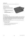
Service aid
We can offer a number of service tools that will simplify the service.
Antistatic service kit
Ordering no. 0740 511 001
The kit makes it easier to protect sensitve
components from electrostatic discharge.
Contents:
S A conductive mat (size 610 x 610 mm)
S A 1.5 metre long ground cable with a
crocodile clip
S An adjustable wrist strap and cable with
an inbuilt protective resistor
Antistatic service kit
Esat service kit
Ordering no. 0458 847 880
The software update is made from a PC, it has to be managed by a trained serviceman. For
this a computer program called Esat, ESAB software administration tool, is needed. The PC
is connected to the welding equipment by a cable connector and a CAN reader. From the
Esat it is possible to update the software in power source, wire feeder and control panel.
Esat contains also service functions by which it is possible to control, change or read the
different functions in the equipment.
For the installation and use of Esat program you need a computer with operating system
Windows 9x, NT4, 2000 or XP.
The Esat service kit contents:
S CAN adapter PPCAN
S Connection Cable between CAN reader and power source
S CAN adapter software and Esat software on CD
S Instruction manual for Esat

S0740 800 152/E061012/P36
-- 1 4 --
ci01f2
Exchange circuit boards
Exchange circuit boards are repaired and tested circuit boards. We offer those boards to a
lower price than new circuit boards. When an exchange circuit board is ordered, the defect
board must be sent back to ESAB. Use only antistatic packaging materials for the
circuit board. If we do not receive the defect board, or if it is not packed in antistatic
packaging, the price for the exchange board will be 30 to 50% higher than the normal price.
Some boards must have a machine ID, for this you need the Esat service kit. In order to
make the service of the machines easy, we offer the boards with individual ordering
numbers, where machine--ID is needed (plug and play). Machine ID is needed for the
boards in the control panels (MMC module).
There are three price levels for the circuit boards, level 1. is the cheapest:
1. Exchange board without machine ID
2. New circuit board without ID
3. Exchange board with machine ID
During the warranty period we only accept the warranty costs for circuit boards without
machine ID.
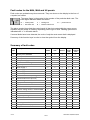
All circuit boards in the spare parts list are new circuit boards without machine ID. Below is
a list of the exchange boards for the M2, MA4 and MA6 control panels.
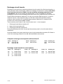
Complete exchange con trol panels with machine ID
Panel Ordering no. Panel Ordering no. Panel Ordering no.
M2 E458 535 882 MA4 E458 535 884 MA6 E458 535 886
U6 E458 535 890 MA6
Exchange circuit boards for control panels
Panel ID Ordering no. Panel ID Ordering no. Panel ID Ordering no.
M2 no E486 819 887 MA4 no E486 819 880 MA6 no E486 819 880
M2 yes E486 819 882 MA4 yes E486 819 884 MA6 yes E486 819 886
U6 no E486 819 880
U6 yes E486 819 890

S0740 800 152/E061012/P36
-- 1 5 --
ci01i_m2
INSTRUCTIONS M2
This chapter is an extract from the instruction manual for the M2 control panel.
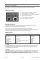
The control panel
1 Knob for selecting 2 / 4--stroke control mode
2 Knob for setting the burn--back time
3 Yellow indicating lamp -- non--specific fault indication
4 Knob for setting the inductance
5 Knob for setting the wire feed speed
6 Knob for setting the arc voltage
Remote control unit
Using a remote control unit, the primary parameters of the welding process can be
controlled from a device other than the control panel.
The remote control unit must be connected via a remote control adapter.
When the remote control adapter is connected, everything is controlled from the remote
control unit, and the knobs on the control panel are out of operation.
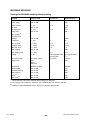
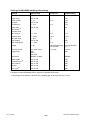
Setting ranges
Welding parameter Setting range Adjustment steps
2/4--stroke 2--stroke or 4--stroke --
Gas pre-- flow preset on 0.1 s not adjustable
Gas post--flow preset on < 0.1 s not adjustable
Burn--back time 0.01 -- 0.35 s stepless
Inductance 30, 50, 70 and 90% of max inductance 4 positions
Wire feed speed 0.8 -- 25.0 m/min stepless
Arc voltage 8--42V stepless
2--stroke
With 2--stroke, the gas pre-- flow begins when the welding gun trigger switch is pressed.
The welding process begins after this. When the trigger switch is released, welding is
stopped and gas post--flow starts.
4--stroke
With 4--stroke, the gas pre-- flow begins when the welding gun trigger switch is pressed.
When the welding gun trigger switch is released, the welding process starts. When the
trigger switch is pressed again, the welding data is reduced to a lower value. When the gun
trigger switch is released, welding is stopped and gas post-- flow starts.

S0740 800 152/E061012/P36
-- 1 6 --
ci01i_ma4
INSTRUCTIONS MA4
This chapter is an extract from the instruction manual for the MA4 control panel.
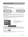
INTRODUCTION
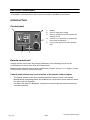
Control panel
1 Display
2 Knob for setting the voltage
3 Knob for setting the wire feed speed and
welding current
4 Increase (+) or Decrease (--) selected by
the function pushbuttons. →
5 First, second and third function pushbut-
tons
Remote control unit
Using a remote control unit, the primary parameters of the welding process can be
controlled from a device other than the control panel.
Machines with intergral control panels should have program version 1.21 or higher, in order
for the remo te control to function correctly.
Control panel’s behaviour on connection of the remote control adapter
S The display freezes in the menu showing when the remote control is connected.
Measurement and setting values are updated, but only shown in those menus in which
the values can be displayed.
S If a fault code symbol is displayed, it cannot be removed until the remote control has
been disconnected.

S0740 800 152/E061012/P36
-- 1 7 --
ci01i_ma4
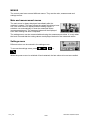
MENUS
The control panel uses several different menus. They are the main, measurement and
settings menus.
Main and measurement menus
The main menu is always displayed immediately after the
machine is started. The menu shows the values which have been
set. If the main menu is displayed when welding begins, it
switches over automatically to show the measured values
(measurement menu). The measured values will be displayed
even after welding has been completed.
The settings menu can be accessed without losing the measurement values. It is only when
the knob is turned that the setting values are displayed instead of the measured values.
Settings menu
Different values can be entered in the settings menu.
To access the settings menu, press
, , or
.
When the power source is switched off and restarted, the last values to be set are recalled.

S0740 800 152/E061012/P36
-- 1 8 --
ci01i_ma4
MIG/MAG WELDING
Settings
Settings Setting range In steps of: Default setting
Welding method MIG/MAG, MMA or
Arc--air gouging
-- MIG/MAG
2/4--stroke* 2--stroke or 4--stroke -- 2-- stroke
Crater filling* ON or OFF -- OFF
Crater filling time 0--5s 0.1 s 1.7 s
Inductance 0 -- 100 1 70
Gas pre-- flow 0.1 -- 25.0 s 0.1 s 0.1 s
Creep start ON or OFF -- ON
Burnback time 1 -- 350 ms 10 ms 100 ms
Gas post--flow 0.1 -- 20 s 1s 0.5 s
Voltage 8--60V 0.25 V (displayed with
one decimal)
12 V
Wire feed speed 0.8 -- 25.0 m/min 0.1 m/min 5m/min
*) These functions cannot be changed while welding is in progress.
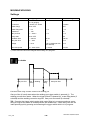
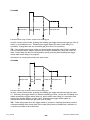
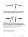
2--stroke
Gas pre-- flow Hot
start
Welding Crater
filling
Gas post--flow
Functions when using 2--stroke control of the welding gun.
Gas pre--flow (if used) starts when the welding gun trigger switch is pressed (1). The
welding process then starts. When the trigger switch is released (2), crater filling starts (if
selected) and the welding current is stopped. Gas post--flow starts (if selected).
TIP: Pressing the trigger switch again while crater filling is in progress continues crater
filling as long as the switch is held depressed (the dotted line). Crater filling can also be
interrupted by quickly pressing and releasing the trigger switch while it is in progress.

S0740 800 152/E061012/P36
-- 1 9 --
ci01i_ma4
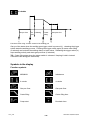
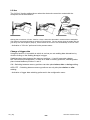
4--stroke
Gas pre-- flow Hot
start
Welding Crater
filling
Gas post--flow
Functions when using 4--stroke control of the welding gun
Gas pre--flow starts when the welding gun trigger switch is pressed (1): releasing the trigger
switch starts the welding process. Pressing the trigger switch again (3) starts crater filling
(if selected) and reduces the welding data to a lower value. Releasing the trigger switch (4)
stops welding entirely and starts gas post--flow (if selected).
TIP: Crater filling stops when the trigger switch is released. Keeping it held in instead
continues crater filling (the dotted line).
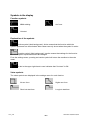
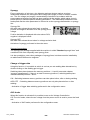
Symbols in the display
Function symbols
MIG/MAG Inductance
2--stroke 4--stroke
Gas pre--flow Gas post--flow
Crater filling Crater filling time
Creep start Burnback time

S0740 800 152/E061012/P36
-- 2 0 --
ci01i_ma4
Explanation of t h e symbols
Active symbol (dark background). Active means that the function which the
symbol represents can be activated. New values can only be set when the symbol is active.
Inactive symbol (light background). Inactive means that settings for the function
which the symbol represents cannot be changed.
From the settings menu, pressing an inactive symbol will return the machine to the main
menu.
A dot in the upper right --hand corner indicates that crater filling is ON.
Value symbols
The value symbols are displaye d in the settings menu for each function.
Lower inductance Higher inductance
No gas flow time Long gas flow time
Creep start ON Creep start OFF
Shorter burnback time Longer burnback time
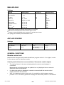
MMA WELDING
Settings
Settings Setting range In steps of Default setting
Welding method MIG/MAG, MMA or
Arc--air gouging
-- MIG
Hot start* ON or OFF -- OFF
Hot start time 1--30 1 10
Arc force 0--10 0.5 3
Current, depending on
machine type
16 -- 500 A 1A 100 A
*) This function cannot be changed while welding is in progress.
Page is loading ...
Page is loading ...
Page is loading ...
Page is loading ...
Page is loading ...
Page is loading ...
Page is loading ...
Page is loading ...
Page is loading ...
Page is loading ...
Page is loading ...
Page is loading ...
Page is loading ...
Page is loading ...
Page is loading ...
Page is loading ...
-
 1
1
-
 2
2
-
 3
3
-
 4
4
-
 5
5
-
 6
6
-
 7
7
-
 8
8
-
 9
9
-
 10
10
-
 11
11
-
 12
12
-
 13
13
-
 14
14
-
 15
15
-
 16
16
-
 17
17
-
 18
18
-
 19
19
-
 20
20
-
 21
21
-
 22
22
-
 23
23
-
 24
24
-
 25
25
-
 26
26
-
 27
27
-
 28
28
-
 29
29
-
 30
30
-
 31
31
-
 32
32
-
 33
33
-
 34
34
-
 35
35
-
 36
36


ESAB MA6 User manual
- Category
- Welding System
- Type
- User manual
Ask a question and I''ll find the answer in the document
Finding information in a document is now easier with AI
