Page is loading ...

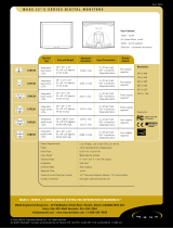
LE-37A
3.5 inch Motherboard
User’s Manual
Edition 1.7
2017/10/26

LE-37A User’s Manual
-1-
Copyright
Copyright 2017, all rights reserved. This document is copyrighted and all rights are
reserved. The information in this document is subject to change without prior notice to
make improvements to the products.
This document contains proprietary information and protected by copyright. No part of
this document may be reproduced, copied, or translated in any form or any means
without prior written permission of the manufacturer.
All trademarks and/or registered trademarks contains in this document are property of
their respective owners.
Disclaimer
The company shall not be liable for any incidental or consequential damages resulting
from the performance or use of this product.
The company does not issue a warranty of any kind, express or implied, including
without limitation implied warranties of merchantability or fitness for a particular purpose.
The company has the right to revise the manual or include changes in the specifications
of the product described within it at any time without notice and without obligation to
notify any person of such revision or changes.
Trademark
All trademarks are the property of their respective holders.
Any questions please visit our website at TUhttp://www.commell.com.twUT

LE-37A User’s Manual
-2-
Packing List:
Please check the package content before you starting using the board.
Hardware:
LE-37A 3.5“ Miniboard x 1
Cable Kit:
SATA Cable x 1
(OALSATA3-L)/ (1040529)
Printed Matters:
Driver CD (Including User’s Manual) x 1
CPU Cooler x 1
(OHS-P-M-7)/ (2181010002)
DVI Module With DVI Cable x 1
(BADPDVIP_A&OALDVI-DF13)
(4120008011&1040483)
DC Power Cable x 1
(OALDC-A)/ (1040433)
USB Cable x 1
(OALUSBA-3)/ (1040173)
PS/2 Keyboard & Mouse Cable x 1
(OALPS2/MKN)/ (1040551)
COM Port Cable x 1
(OALES-BKU1NB)/ (1040086)
Audio Cable x 1
(OALPJ-HDUNB)/ (1040123)
1 to 3 power output cable x 1
(OAL4P-2)/ (1040051)
SATA Power Cable x 1
(OAL4P-S2)/ (1040054)

LE-37A User’s Manual
-3-
Index
Chapter 1 <Introduction> ..............................................................................6
1.1 <Product Overview>..................................................................................... 6
1.2 <Product Specification>................................................................................ 7
1.3 <Mechanical Drawing>................................................................................. 9
1.4 <Block Diagram>........................................................................................ 10
Chapter 2 <Hardware Setup>...................................................................... 11
2.1 <Connector Location> ................................................................................ 11
2.2 <Jumper Location & Reference>................................................................ 13
2.3 <Connector Reference> ............................................................................. 14
2.3.1 <Internal Connectors> ................................................................... 14
2.3.2 <External Connectors> .................................................................. 14
2.4 <CPU and Memory Setup> ........................................................................ 15
2.4.2 <Memory Setup> ........................................................................... 15
2.5 <CMOS & ATX Setup> ............................................................................... 16
2.6 <Serial ATA Interface> ................................................................................ 17
2.7 <Ethernet Interface>................................................................................... 17
2.8 <Onboard Display Interface> ..................................................................... 18
2.8.1 <Analog Display>........................................................................... 18
2.8.2 <Digital Display>............................................................................ 19
2.8.3 <DVI Interface>.............................................................................. 24
2.9 <Integrated Audio Interface> ...................................................................... 25
2.10 <USB Interface>....................................................................................... 27
2.11 <Serial Port>............................................................................................. 28
2.12 <PCIE Mini Card and SIM Interface> ....................................................... 30
2.12.1 <SIM Setup>................................................................................ 32
2.13 <GPIO and SMBUS Interface>................................................................. 34
2.14 <Power Supply and Fan Interface >......................................................... 35
2.14.1 <Power Input> ............................................................................. 35
2.14.2 <Power Output>........................................................................... 35
44-pin

LE-37A User’s Manual
-4-
2.14.3 <Fan connector>.......................................................................... 36
2.15 <Switch and Indicator>............................................................................. 37
Chapter 3 <System Setup> .........................................................................38
3.1 <Audio Configuration>................................................................................ 38
3.2 <Display Properties Setting>...................................................................... 39
Chapter 4 <BIOS Setup> ............................................................................. 41
Appendix A <I/O Port Pin Assignment>.....................................................43
A.1 <Serial ATA Port> ....................................................................................... 43
A.2 <IrDA Port> ................................................................................................ 43
A.3 <VGA Port>................................................................................................ 43
A.4 <LAN Port> ................................................................................................ 43
A.5 <LAN LED Port> ........................................................................................ 44
A.6 <LPC Port> ................................................................................................ 44
Appendix B <Flash BIOS> ..........................................................................45
Appendix C <System Resources> .............................................................46
C.1 <I/O Port Address Map> ............................................................................ 46
C.2 <Memory Address Map>............................................................................ 48
C.3 <System DMA & IRQ Resources> ............................................................. 49
Appendix D <Programming GPIO’s> .........................................................50
Appendix E <Programming Watchdog Timer > ........................................ 51

LE-37A User’s Manual
-5-
(This page is left for blank)

LE-37A User’s Manual
-6-
Chapter 1 <Introduction>
1.1 <Product Overview>
LE-37A the 2
nd
Generation Intel of the Mini-ITX motherboard, supports 2
nd
Generation
Intel Celeron® Processor 807UE/827E/847E and features Intel HM65 chipset,
integrated HD Graphics, DDR3 memory, REALTEK High Definition Audio, Serial ATA
and Intel Gigabit LAN.
Intel Sandy Bridge Processor
The 2nd Generation Intel Celeron® Processor 807UE/827E/847E is the next generation
of 64-bit, multi-core mobile processor built on 32- nanometer process technology. Based
on a new micro-architecture.
New features for Intel QM67 chipset
The board integrates Intel HM65 chipset, supports integrated HD Graphics, built-in high
speed mass storage interface of serial ATA, High Definition Audio with 2 channels
surrounding sound.
All in One multimedia solution
Based on Intel HM65 chipset, the board provides high performance onboard graphics,
24-bit dual channel LVDS interface, DVI and 2 channels High Definition Audio, to meet
the very requirement of the multimedia application.
Flexible Extension Interface
The board provides two PCIE mini card socket.

LE-37A User’s Manual
-7-
1.2 <Product Specification>
General Specification
Form Factor
3.5 inch miniboard
CPU
Intel ® Celeron® Processor 807UE 1.0GHz (LE-37ANB)
Intel® Celeron® Processor 827E 1.4GHz (LE-37AC6)
Intel® Celeron® Processor 847E 1.1GHz (LE-37ABU)
Package type:FCBGA1023
Memory
1 x DDRIII SO-DIMM 1066/1333 MHz up to 4GB
(LE-37ANB)
1 x DDRIII SO-DIMM 1066/1333 MHz up to 8GB
(LE-37AC6 / LE-37ABU)
Support Non-ECC, unbuffered memory only
Chipset
Intel® HM65
Watchdog Timer
Generates a system reset with internal timer for 1min/s ~
255min/s
Real Time Clock
Chipset integrated RTC with onboard lithium battery
Serial ATA
2 x serial ATAIII interface with 600MB/s transfer rate
Optional support mSATA(SATAII) for Mini_Card2
Multi-I/O Port
Chipset
Winbond W83627DHG-P
Serial Port
One RS-232/422/485 serial port and one RS-232
USB Port
Six Hi-Speed USB 2.0 ports
with 480Mbps of transfer rate
IrDA Port
One IrDA compliant Infrared interface supports SIR
K/B & Mouse
PS/2 keyboard and mouse port
GPIO
One 12-pin Digital I/O connector with 8-bit programmable I/O
interface
VGA Display Interface
Chipset
Intel® HD Graphics
Display Type
CRT, LCD monitor with analog display, single channel LVDS
Can support MPX-SDVOD/X for Mini_Card1
Connector
External DB15 female connector
Onboard 40-Pin LVDS and 5-Pin inverter connector
Onboard 20-Pin DVI
Ethernet Interface
Controller
1 x Intel® 82579LM Gigabit Ethernet controller
Type
Triple speed 10/100/1000Base-T
Auto-switching Fast Ethernet
Full duplex, IEEE802.3U compliant
Connector
One External RJ45 connector with LED

LE-37A User’s Manual
-8-
Audio Interface
Chipset
REALTEK ALC888
Interface
Stereo audio Line-out and MIC-in
Connector
Onboard audio connector with pin header
Expansive Interface
PCIE Mini Card
2 x PCIE Mini Card socket
Power and Environment
Power Requirement
DC 9V~24V input with onboard 4-pin connector
Dimension
146 (L) x 101(H) mm
Temperature
Operating within 0 ~ 60℃
Storage within -20 ~ 85℃
Ordering Code
LE-37ANB
Intel® Celeron® Processor 807UE with Onboard VGA, LVDS,
DVI, Giga LAN, USB2.0, HD Audio, SATAIII, SMBUS, LPC,
GPIO, PCIE mini card
LE-37ANBS
Intel® Celeron® Processor 807UE with Onboard VGA, LVDS,
DVI, Giga LAN, USB2.0, HD Audio, SATAIII, SMBUS, LPC,
GPIO, PCIE mini card, mSATA
LE-37AC6
Intel® Celeron® Processor 827E with Onboard VGA, LVDS,
DVI, Giga LAN, USB2.0, HD Audio, SATAIII, SMBUS, LPC,
GPIO, PCIE mini card
LE-37AC6S
Intel® Celeron® Processor 827E with Onboard VGA, LVDS,
DVI, Giga LAN, USB2.0, HD Audio, SATAIII, SMBUS, LPC,
GPIO, PCIE mini card, mSATA
LE-37ABU
Intel® Celeron® Processor 847E with Onboard VGA, LVDS,
DVI, Giga LAN, USB2.0, HD Audio, SATAIII, SMBUS, LPC,
GPIO, PCIE mini card
LE-37ABUS
Intel® Celeron® Processor 847E with Onboard VGA, LVDS,
DVI, Giga LAN, USB2.0, HD Audio, SATAIII, SMBUS, LPC,
GPIO, PCIE mini card, mSATA
The specifications may be different as the actual production.
For further product information please visit the website at TUhttp://www.commell.com.twUT

LE-37A User’s Manual
-9-
1.3 <Mechanical Drawing>

LE-37A User’s Manual
-10-
W83627DHG-P
1.4 <Block Diagram>
HM65
1 x Intel 82579LM
1 x RS232/422/485
1 x COM
GPIO & IrDA & LPC
2
nd
Generation
Intel ® Celeron® Processor
807UE / 827E / 847E
1 x 204-pin DDR3
SO-DIMM
1066/1333 MHz
up to 4 or 8 GB
1 x LVDS
2 x PCI Express mini card
1 x DVI
1 x CRT
2 x Serial ATAIII
ALC888 HD Audio
W25X64 SPI
6 x USB 2.0

LE-37A User’s Manual
-11-
Chapter 2 <Hardware Setup>
2.1 <Connector Location>
SATA1
SATA2
CN_AUDIO
CD_IN
CN_INV
CN_COM2
CN_DIO
CN_SMBUS
CN_IR
JFRNT
SYSFAN
CPUFAN
DC_OUT
DC_IN
CN_USB1
CN_USB2
CN_LPC
CN_LVDS
CN_DVI
SIMM
MINI_CARD2
MINI_CARD1
JACT
JSPD

LE-37A User’s Manual
-12-
PS2
RJ45
CRT
COM1
SO-DIMM
USB

LE-37A User’s Manual
-13-
2.2 <Jumper Location & Reference>
Jumper
Function
JRTC
CMOS Operating/Clear Setting
JVLCD
Panel Voltage Setting
JAT
Power mode select
JP1
Com1 Voltage Setting (For Pin 9)
JP2
Com2 Voltage Setting (For Pin 9)
JCSEL1
JCSEL2
CN_COM2 RS-232 RS422 RS485 Setting
CN_IR IrDA Setting
JCSEL2
JP2
JCSEL1
JAT
JP1
JRTC
JVLCD

LE-37A User’s Manual
-14-
2.3 <Connector Reference>
2.3.1 <Internal Connectors>
Connector
Function
Remark
SO-DIMM
204 -pin DDR3 SO-DIMM socket
SATA 1/2
7-pin Serial ATAIII connector
DC_IN
DC 9~24V input connector
DC_OUT
4-pin DC output connector
CN_AUDIO
5 x 2-pin audio connector
CD_IN
4-pin CD-ROM audio input connector
CN_DIO
6 x 2-pin digital I/O connector
CN_USB 1/2
5 x 2-pin USB connector
CPUFAN
4-pin CPU cooler fan connector
SYSFAN
3-pin system cooler fan connector
CN_LVDS
20 x 2-pin LVDS connector
CN_INV
5-pin LCD inverter connector
CN_IR
5-pin IrDA connector
CN_COM2
9-pin RS232/485/422
CN_LPC
5 x 2-pin LPC connector
JFRNT
10-pin front panel switch/indicator
connector
Mini-PCIE1/2
52-pin Mini-PCIE socket
JAT
Power mode select
JSPD
LAN Speed LED connector
JACT
LAN Activity LED connector
2.3.2 <External Connectors>
Connector
Function
Remark
COM1
DB9 Serial port connector
CRT
DB15 VGA connector
PS2
PS/2 keyboard and mouse connector
USB
Dual USB 3.0 connector for USB 2.0 Interface
RJ45
RJ45 LAN connector

LE-37A User’s Manual
-15-
2.4 <CPU and Memory Setup>
2.4.2 <Memory Setup>
The board provides 204-pin DDR3 SO-DIMM to support 1066/1333MHz DDR3 memory
module up to 4GB(LE-37ANB) or 8GB(LE-37AC6/BU).
Support Non-ECC, unbuffered memory only
SO-DIMM

LE-37A User’s Manual
-16-
2.5 <CMOS & ATX Setup>
The board’s data of CMOS can be setting in BIOS. If the board refuses to boot due
to inappropriate CMOS settings, here is how to proceed to clear (reset) the CMOS
to its default values.
Jumper: JRTC
Type: Onboard 3-pin jumper
JRTC
Mode
1-2
Clear CMOS
2-3
Normal Operation
Default setting: 2-3
The board has a jumper to switch AT power mode (automatic power on) or standard
ATX mode (manual power on).
Jumper: JAT
Type: onboard 3-pin jumper
JAT
Mode
1-2
AT Mode
2-3
ATX Mode
Default setting:2-3
JRTC
JAT
1 3
1 3

LE-37A User’s Manual
-17-
2.6 <Serial ATA Interface>
Based on Intel PCH, the board provides two Serial ATAIII interfaces with up to 600MB/s
of transfer rate .
2.7 <Ethernet Interface>
The board integrates with one Intel 82579LM controllers, The Intel Gigabit Ethernet
supports triple speed of 10/100/1000Base-T, with IEEE802.3 compliance.
RJ45 LAN connector
SATA1
SATA2

LE-37A User’s Manual
-18-
2.8 <Onboard Display Interface>
Based on Intel Sandy Bridge CPU with built-in HD Graphic, the board provides one DB15
connector on real external I/O port, one 40-pin LVDS interface with 5-pin LCD backlight
inverter connector and provides 26-pin DVI interface.
The board provides dual display function with clone mode and extended desktop mode
for CRT, LCD and DVI.
2.8.1 <Analog Display>
Please connect your CRT or LCD monitor with DB15 male connector to the onboard
DB15 female connector on rear I/O port.
CRT

LE-37A User’s Manual
-19-
2.8.2 <Digital Display>
The board provides one 40-pin LVDS connector for 24-bit single/dual channel panels,
supports up to 2048 x 1536 (UXGA) resolution, with one LCD backlight inverter
connector and one jumper for panel voltage setting.
Effective patterns of connection: 1-2 / 3-4 / 5-6
Warning: others cause damages
JVLCD
2
1
5
6
1
5
1
2
3
4
5
6
CN_LVDS
40
39
2
1
CN_INV
/