Page is loading ...

COPYRIGHT © MARCH, 2016 BY GRIZZLY INDUSTRIAL, INC.
WARNING: NO PORTION OF THIS MANUAL MAY BE REPRODUCED IN ANY SHAPE
OR FORM WITHOUT THE WRITTEN APPROVAL OF GRIZZLY INDUSTRIAL, INC.
#MC17956 PRINTED IN CHINA
The T27451 15" & T27452 20" indexable insert
spiral cutterheads are designed to fit Grizzly
planer Models G0453W, G0453ZW, G0454W,
and G0454ZW.
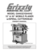
Inventory
A. Spiral Cutterhead with Carbide Inserts ...... 1
B. T-Handle Torx Driver T20 ........................... 1
C. L-Handle Torx Driver T20 ........................... 1
D. Cutterhead Inserts 14 x 14 x 2 ................... 5
E. Flat Head Torx Screws M6-1 x 15 .............. 3
Figure 1
. Model T27451/T27452 inventory.
A
B
C
D
E
Recommended Tools
Metric Hex Set (3mm, 5mm, 6mm) .............1 Ea.
Wooden Blocks 2x4 x 4" ................................... 6
Pair of Heavy Leather Gloves ........ 1 Per Person
Wooden or Rubber Mallet ................................. 1
Steel Hammer ................................................... 1
Screw or Bolt M6-1 x 25 .................................... 1
Open-End Wrench 12 x 14 ............................... 1
Shop Rags ......................................... As Needed
Drain Pan .......................................................... 1
Gear Case Oil ISO 320 .................... As Needed
Oil Funnel .......................................................... 1
Assistants ....................................................... 1-2
Sprocket/Pulley Puller ....................................... 1
Open-End Wrench to Fit Pulley Puller............... 1
Heavy Cardboard ............................. As Needed
Heav y Tape ....................................... As Needed
Replacement Bearings ...................................... 2
Replacement Gaskets and Seals ...... As Needed
Specifications
T27451
Maximum Width of Cut ................................... 15"
Cutterhead Diameter .................................. 2-7/8"
Number of Indexable Carbide Inserts ............. 72
T27452
Maximum Width of Cut ...................................20"
Cutterhead Diameter .................................. 3-1/8"
Number of Indexable Carbide Inserts ............. 96
The total procedure of changing the cutterhead
and setting up the planer takes approximately
three hours. Read these instructions thoroughly
before beginning. We strongly recommend
replacing the old cutterhead bearings at the time
of installation. The T27451 uses two 6205ZZ
bearings. The T27452 uses two 6206ZZ bearings.
Note: Not all pictures in these instructions will
exactly reflect your machine. Some photos are
provided for representation purposes only to help
you better understand the concepts described in
the procedure.
For questions or help with this product contact Tech Support at (570) 546-9663 or techsupport@grizzly.com
MODEL T27451/T27452
15" & 20" SPIRAL
CUTTERHEAD
INSTRUCTIONS
Do NOT modify or alter these cutterheads
to make them fit other makes or models
of planers for which they aren't designed.
Doing so could result in property damage or
serious personal injury.

-2-
T27451/T27452 15" & 20" Spiral Cutterheads
8. Remove the table elevation handwheel and
key.
Figure 2. Using a pulley puller.
1. DISCONNECT MACHINE FROM POWER!
2. Remove top cover and dust port to expose
cutterhead.
3. Remove knives from existing cutterhead.
4. Remove belt cover, and then remove V-belts
from pulleys.
Note: This may require loosening belt ten-
sion. This procedure is outlined in SERVICE
section of your planer manual.
5. Remove hex bolt securing cutterhead pulley
in place.
6. Rotate cutterhead until cutterhead pulley key
is at an upright position.
7. Remove pulley and key. If pulley is difficult
to remove, use a pulley puller, as shown in
Figure 2 (see Page 7 of this instruction sheet
if you do not have a pulley puller).
9. Remove both rear guards from sprocket
cover, as shown in Figure 3.
10. Remove sprocket cover cap screw and
sprocket cover.
Figure 3. Sprocket cover rear guards.
11. Remove cap screws and washers from three
sprockets, shown in Figure 4, to expose
sprocket keys.
12. Unhook idler spring shown in Figure 4 and
move idler up out of the way.
13. Rotate cutterhead so sprocket keys are in a
generally upright position. This prevents keys
from falling out.
14. Mark outside of sprockets with correction
fluid as a way of remembering which side of
each sprocket faces outward.
Figure 4. Example of sprockets and chains.
Idler
Idler Spring
Key
Key
Key
Cutterhead knives and inserts are razor
sharp! Always wear heavy leather gloves
when handling cutterheads, and avoid
contact with cutters whenever possible.
Failure to comply can result in serious cuts
or laceration injuries.
Removing Existing Cutterhead

T27451/T27452 15" & 20" Spiral Cutterheads
-3-
15. Remove sprockets, keys and chains all at
once, taking care to keep chains intact.
16. Thoroughly drain the planer gearbox into a
drain pan by removing drain plug shown in
Figure 5.
Figure 7. Gearbox cap screw location.
Figure 5. Drain and fill plug location.
17. Insert (6) 4" 2x4 blocks directly beneath the
cutterhead, as shown in Figure 6.
15" PLANER
4" 2x4 Blocks
Figure 6. Support block location (6) 4" 2x4's.
18. Re-install the handwheel and key, and care-
fully raise the table so cutterhead just touch-
es blocks.
19. Remove the four cap screws at the top of the
gearbox, shown in Figure 7.
Fill Plug
Drain Plug
Note: For the 20" G0454W model, remove
pressure plate tension spring located beneath
chip deflector (see Figure 8).
Figure 8. Chip deflector before removal.
Chip Deflector
20. Have an assistant hold gearbox steady while
you use a rubber or wooden mallet to unseat
cutterhead out from headstock, as shown in
Figure 9.
Figure 9. Unseating cutterhead from headstock.

-4-
T27451/T27452 15" & 20" Spiral Cutterheads
24. Remove the cap screw from inside helical
gear, shown in Figure 10, and remove the
sprocket.
25. Insert spare M6-1 screw or bolt into hole
at gearbox end of the cutterhead shown in
Figure 11.
Figure 12. Cutterhead removal.
27. Visually inspect all bearing bores, both on the
headstock and in the gearbox, and remove
any burrs or rough spots that are present.
Installing Spiral Cutterhead
We recommend that all gearbox seals and gas-
kets are replaced before cutterhead installation,
even if the seals or gaskets appear to be in good
condition.
NOTICE
Before removing any seals, note their
orientation and how far they are driven into
the bore (typically the lip of a seal will face
inward toward the oil reservoir or body
of liquid). This will aid in the replacement
process. Failure to heed this notice can lead
to fluid leakage and gearbox failure.
Figure 10. Helical gear and cap screw.
Cap Screw
Helical Gear
26. While supporting the gearbox, remove the
cutterhead by tapping on the screw or bolt
with a hammer, as shown in Figure 12. It
may also be necessary to tap on the back of
the gearbox with a rubber or wooden mallet.
Figure 11. Location of screw hole in cutterhead
removal.
Gearbox
Bearing
Screw Hole
21. Pull cutterhead gearbox assembly off planer
and place on workbench.
22. Remove five cap screws from front of
gearbox cover.
23. Separate gearbox cover by gently tapping
near the gasket using a mallet and flat head
screwdriver.
1. Wrap new cutterhead in the cardboard and
securely fasten it with heavy tape.
2. Install a new bearing on the cutterhead by
very gently tapping it on, using a mallet and
a 4" length of 1" inside diameter (I.D.) pipe,
as shown in Figure 13 on Page 5.
Tip: Place the wrapped cutterhead in a freez-
er overnight before installing a new bearing.
This will cause the cutterhead metal to con-
tract, making the bearing easier to install.
Important: The pipe should contact the
inside race of the bearing only, as shown in
Figure 13. Force on any other portion of the
bearing WILL ruin the bearing!

T27451/T27452 15" & 20" Spiral Cutterheads
-5-
Figure 13. Close-up of bearing installation.
Cutterhead
Cutterhead
Shaft
1" I.D. Pipe
(cut-away for
clarity)
Contact Inside
Bearing Race
Only
8. Secure the gearbox in place with the cap
screws removed in Step 19 of the Cutterhead
Removal instructions.
9. Refill the gearbox with ISO 320 sprocket oil
via the fill plug shown in Figure 5.
10. Rotate all sprocket shafts so that the key-
ways are in a generally upward position. This
prevents keys from falling out during installa-
tion of sprockets.
11. Re-install the sprockets, chains and idler.
Fasten the sprockets using the washers and
cap screws removed as noted in Step 11 on
Page 2.
12. Re-install the sprocket cover, including both
rear guards, on the sprocket cover.
13. With the cutterhead shaft keyway in an
upright position, install the cutterhead pulley
key into the keyway.
14. Slide the cutterhead pulley onto the shaft,
and secure with the hex bolt removed in Step
5 of the Cutterhead Removal instructions.
15. Remove the protective cardboard and tape
from around the cutterhead.
16. Re-install all belts and the belt cover.
Re-adjust the V-belt tension if it was loos-
ened in Step 4 of the Cutterhead Removal
instructions.
17. Re-install all remaining covers and guards.
18. Follow the procedures outlined in your planer
manual for the adjustment and calibration of
your planer.
Figure 14. Example of seating cutterhead-
gearbox assembly.
3. Install the cutterhead in the gearbox by fitting
it into place, and seat it by tapping on the
pulley end with a wooden or rubber mallet.
Ensure the cutterhead end is flush with the
inside face of the gearbox bearing, as previ-
ously shown in Figure 11 on Page 4.
4. Re-install the helical gear and cap screw,
ensuring the helical gear and the cutterhead
are engaged.
5. Ensure that gasket surfaces are clean and
free of oil, grit or contaminants. If these are
damaged, replace them.
6. Re-assemble the gearbox, taking care to seat
the rubber gasket in alignment with the gear-
box covers.
7. Install the cutterhead-gearbox assembly into
the planer. Seat the cutterhead shaft bearing
by tapping on the gearbox with a rubber or
wooden mallet, as shown in Figure 14.

-6-
T27451/T27452 15" & 20" Spiral Cutterheads
Rotating/Changing Carbide Inserts
Tools Needed:
T-Handle Torx Driver T20 .................................. 1
L-Handle Torx Driver T20 .................................. 1
Number of Inserts
T27451 ............................................................. 72
T27452 ............................................................. 96
Each insert can be rotated to reveal any one of its
four cutting edges. Therefore, if one cutting edge
becomes dull or damaged, simply rotate it 90˚ to
reveal a fresh cutting edge (see Figure 15).
In addition, each insert has a reference dot on
one corner. As the insert is rotated, the refer-
ence dot location can be used as an indicator of
which edges are used and which are new. When
reference dot revolves back around to its starting
position, the insert should be replaced.
5. Lubricate the Torx screw threads with light
machine oil, wipe off the excess oil, and
torque the Torx screw to 48-50 inch/pounds.
Note: Excess oil may squeeze between
the insert and cutterhead, thereby lifting
the insert slightly and affecting workpiece
finishes.
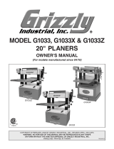
Accessories
G8995—4" Heavy-Duty Pulley Puller
Indispensable for pulling gears or pulley off of
press-fit shafts. 4" jaw fingers can be used in
either a 2 or 3 jaw configuration.
Figure 16. G8995 4" Heavy Duty Pulley Puller.
H7319—10 Pack of Indexable Carbide Inserts
Replacement carbide inserts for T27451 and
T27452 cutterheads.
Figure 17. H7319 Indexable Carbide Inserts.
Figure 15. Carbide insert rotating sequence.
Reference Dot
To rotate or change a carbide insert:
1. DISCONNECT MACHINE FROM POWER!
2. Remove any sawdust from the head of the
carbide insert Torx screw.
3. Remove the Torx screw and carbide insert.
4. Clean all dust and dirt off the insert and the
cutterhead pocket from which the insert was
removed, and replace the insert so a fresh,
sharp edge is facing outward.
Note: Proper cleaning is critical to achieving
a smooth finish. Dirt or dust trapped between
the insert and cutterhead will slightly raise the
insert, and make a noticeable marks on your
workpieces the next time you plane.

T27451/T27452 15" & 20" Spiral Cutterheads
-7-
T27451 Parts Breakdown and List
4
1
2
3
4
5
REF PART # DESCRIPTION
1 PT27451001 SPIRAL CUTTERHEAD
2 PT27451002 FLAT HD TORX SCR T20 M6-1 X 15
3 PT27451003 INDEXABLE INSERT 14 x 14 x 2
4 PT27451004 T-HANDLE TORX DRIVER T20
5 PT27451005 L-HANDLE TORX DRIVER T20
T27452 Parts Breakdown and List
1
4
2
3
4
5
REF PART # DESCRIPTION
1 PT27452001 SPIRAL CUTTERHEAD
2 PT27452002 FLAT HD TORX SCR T20 M6-1 X 15
3 PT27452003 INDEXABLE INSERT 14 x 14 x 2
4 PT27452004 T-HANDLE TORX DRIVER T20
5 PT27452005 L-HANDLE TORX DRIVER T20

/