Page is loading ...

SERIES 70 AND 1800
CONSUMER ELECTRIC PUMPS
INSTALLATION/OPERATION/PARTS
MANUAL
035219
REV. 0259
INSTALLERS - IMPORTANT
In addition to installation information, this manual contains warnings, safeguards
and procedures on the use and care of the Series 70 and 1800 pumps. Please leave
this manual with the pump owner after the installation is complete.
Copyright 1999 by Gasboy International, Inc. All rights reserved.
The information in this document is confidential and proprietary. No further disclosure shall be made without
permission from Gasboy International, Inc. Gasboy International, Inc. believes that the information in this document
is accurate and reliable. However, we assume no responsibility for its use, nor for any infringements of patents or
other rights of third parties resulting from its use. We reserve the right to make changes at any time without notice.
GASBOY INTERNATIONAL, INC. A TOKHEIM SUBSIDIARY LANSDALE, PA

035282 Rev. 0215
GASBOY INTERNATIONAL, INC.
A TOKHEIM SUBSIDIARY
707 North Valley Forge Rd. Lansdale, PA, 19446
●
(215) 855-4631
●
FAX: (215) 855-0341
IMPORTANT WARNINGS AND SAFEGUARDS
Gasoline and petroleum products are flammable. To avoid injury or death to persons or damage to equipment or
property, follow these listed warnings and other warnings and precautions outlined in this manual when installing, using,
or working around this equipment. Check with GASBOY Technical Services for compatibility of liquids with pump
materials.
TURN OFF AND LOCK OUT ALL POWER TO PUMP BEFORE PERFORMING SERVICE, MAINTENANCE OR IN THE EVENT
OF A FUEL SPILL.
All products must be installed by a
qualified installer and used in
conformance with all building, fire, and
environmental codes and other safety
requirements applicable to its
installation and use, including, but not
limited to, NFPA 30, NFPA 30A, NFPA
395 & NFPA 70. A qualified installer is
familiar with fuel systems installations
under the above stated building, fire,
and environmental codes and other
safety requirements for the particular
type of installation.
This product is only part of a fuel
dispensing system and additional
equipment and accessories, such as,
but not limited to, breakaway
connectors, shear valves, pressure
regulators, flow limiters, and other
safety devices may be necessary to
meet the applicable codes.
For maximum safety, we recommend
that all employees be trained as to the
location and procedure for turning off
power to the entire system. Instructions
regarding proper operation of the
equipment along with the appropriate
safety warnings should be posted in
plain view at the fuel island.
Before performing service or
maintenance (including changing of fuel
filters or strainers) or in the event of a
fuel spill, turn off and lock out all power
to the system. In battery-powered
pumps, disconnect power source. In
submersible pump applications, turn off
and lock out power at the master panel
and close any impact valves to the
submersible pump and any other
dispensers which use that submersible
pump. AC power can feed back into a
shut-off dispenser when dispensers
share a common submersible pump or
starter relay. Also block islands so no
vehicles can pull up to the dispenser
when the dispenser is being worked on.
Federal DOT regulations prohibit
dispensing flammables, such as
gasoline, from portable tanks.
DO NOT
use Teflon tape for any pipe
threads in the product.
DO NOT
use consumer pumps for
pumping fuel or additives into aircraft.
DO NOT
use commercial pumps for
direct fueling of aircraft without filters
and separators necessary to ensure
product purity.
DO NOT
use where sanitary design is
required (for food products for human
consumption) or with water-based
liquids.
DO NOT
smoke near the pump or when
using the pump.
DO NOT
use near open flame or
electrical equipment which may ignite
fumes.
DO NOT
permit the dispensing of
gasoline or other petroleum products
into a vehicle with its motor running.
DO NOT
permit the dispensing of
gasoline or other petroleum products
into unapproved containers or into
approved containers in or on vehicles
including trucks. All containers must be
filled on the ground to prevent static
discharge. Always use Approved and
Listed hoses and nozzles with electric
pumps and dispensers.
DO NOT
block open the nozzle in any
manner. Nozzles shall conform to UL
and NFPA code requirements for
attended or unattended service.
DO
ensure that the pump is equipped
with proper filters based on the product
being dispensed and its intended use.
DO
wear safety goggles and protective
clothes when dispensing any liquid
which may be potentially harmful or
hazardous.
DO
keep all parts of body and loose
clothing clear of belts, pulleys, and other
exposed moving parts at all times.
DO
require washing and changing of
clothes if fuel is spilled on a person or
his/her clothing. Keep away from open
flames, sparks, or people smoking.
DO
provide a receptacle for catching
product from pump/meter when
servicing.
DO
clean up product spills on the
driveway. Turn off and lock out all
power prior to cleanup.
DO
insure pump is properly grounded.
DO
insure hose is compatible with fluid
being dispensed.
DO
inspect hose, nozzle, and pump on
a regular basis for wear, damage, or
other conditions which may create a
safety or environmental hazard.
DO
make sure all pipe threads are
properly cut and the inside reamed to
remove burrs. Use UL classified
gasoline-resisting compound on all
joints of gasoline handling piping.
Sealing compound must also be
resistant to Gasohol (Ethanol and
Methanol). Use gasoline-resistant pipe
compound on male threads only; pipe
compound used on female threads can
be squeezed into the supply line where
it can enter the product stream and
become lodged in the pump or meter.
DO
ensure that junction box covers are
in place and properly tightened. Mating
surfaces between the box and cover
must be free of dirt, nicks, and
scratches. All unused entries into the
junction box must be properly plugged.

0144 Contents-1
CONTENTS
IMPORTANT WARNINGS AND SAFEGUARDS FOR CONSUMER PUMPS
Section 1: INTRODUCTION
Purpose..................................................................................................... 1-1
Specifications* .......................................................................................... 1-1
Section 2: INSTALLATION
Installation Precautions............................................................................. 2-1
Supply Line - Underground Tanks............................................................ 2-2
Pump Dimensions - Series 70, Model 1820 ............................................. 2-3
Pump Dimensions - Series 1820R............................................................ 2-3
Installation Instructions ............................................................................. 2-4
Cabinet Removal for Installation or Service (Series
1820 only - Rounded Cabinet).......................................................... 2-4
Cabinet Removal for Installation or Service (Series
1820 only - Squared Cabinet)........................................................... 2-4
Installing Hose and Nozzle.................................................................. 2-4
Direct Mount on Underground Tank.................................................... 2-5
Direct Mount on Aboveground Tank.................................................... 2-6
Pedestal Mount Pump......................................................................... 2-7
Wall Mount........................................................................................... 2-8
Vacuum Breaker.................................................................................. 2-9
Section 3: WIRING
Wiring Precautions.................................................................................... 3-1
Circuit Breakers........................................................................................ 3-1
Grounding................................................................................................. 3-2
The Pump Motor....................................................................................... 3-2
Wire Size .................................................................................................. 3-2
Pulser Wiring............................................................................................ 3-3
Conduit...................................................................................................... 3-3
Pump Wiring Diagrams............................................................................. 3-4
Section 4: STARTUP AND OPERATION
Pre-Startup Checklist................................................................................ 4-1
Startup ...................................................................................................... 4-1
Post Startup Tests.................................................................................... 4-2
Voltage................................................................................................. 4-2
Tightness............................................................................................. 4-2
Meter Calibration ................................................................................. 4-2
Strainer Cleaning................................................................................. 4-3
Daily Operation ......................................................................................... 4-3
Section 5: MAINTENANCE AND TROUBLESHOOTING
Maintaining Trouble-Free Operation......................................................... 5-1
When Your Pump Needs Service............................................................. 5-2

GASBOY Series 70 & 1800
Contents-2 0144
Troubleshooting........................................................................................ 5-3
Disassembly of Pump............................................................................... 5-5
Meter-Register Disassembly..................................................................... 5-5
1860 3-Wheel Register Service and Maintenance ................................... 5-6
4860 4-Wheel Register Service................................................................ 5-7
Section 6: PARTS
Series 70 Assembly.................................................................................. 6-2
Optional Accessories........................................................................... 6-3
Series 1800 Assembly.............................................................................. 6-4
Optional Accessories........................................................................... 6-5
Direct Drive Motor-Pump Assembly.......................................................... 6-6
Installation Parts ....................................................................................... 6-8
1860 and 4860 Meter-Register................................................................. 6-9
Register Assemblies................................................................................. 6-9
1860 3-Wheel Meter Register (Model 1820) ............................................ 6-10
4860 4-Wheel Register (Model 72S and Series 1820R) .......................... 6-12
Model 1820 Register Setback and Switch Linkage Assembly.................. 6-14
Optional Kits for Series 70 and 1800 Pumps............................................ 6-15
Series 1820R Parts List............................................................................ 6-16
1820R Pulser and Junction Box Assemblies............................................ 6-18
Warranty

9312 1-1
Section 1
INTRODUCTION
PURPOSE
The GASBOY
Series 70 and 1820 Consumer Electric Pumps Installation/Operation Manual
is
provided to assist the installer in installing and operating the unit. Faulty installations are the
major cause of unit malfunctions. This manual should be supplied to the electrician prior to the
installation of conduit and wiring. The Series 70 or 1820 pumps
must
be installed and operated
as described in this manual. This manual also contains warnings, safeguards and procedures on
the use and care of the pump. Be sure to leave this manual with the pump owner after the
installation is complete.
☎
☎☎
☎
Customers and installers having any questions pertaining to the installation should
contact their GASBOY distributor.
SPECIFICATIONS
Series 70 and Series 1820 pumps are made specifically for private use on vented tanks. While
their outward appearance differs, they basically offer the same features. These pumps can be
mounted on aboveground skid tanks, directly mounted above underground tanks, or mounted on
pedestals for remote underground installations. Table 1-1 summarizes the features for each
model.
Pumping Unit: Self-priming, direct-drive rotary vane; 23 PSI (1.6 bars) stainless steel bypass; check
valve with pressure relief valve.
Motor: 1/3 HP, 1725 RPM motor with thermal overload protection and auxiliary AC line.
Standard 115 VAC, 60 Hz; optional 230 VAC, 50 Hz. AC junction box included.
Register: 70: 4-wheel push-button reset, 7-digit master totalizer
1820: 3-wheel, volume only; lever-type reset with interlock; 6-digit master totalizer
(Optional, except for 1820R: 4-wheel push-button)
Registers show delivery in US gallons, Imperial gallons, or liters and change gears are
available to convert registers for unit of measure.
Meter: Nutating disk phenolic measuring chamber in aluminum die-cast housing; adjustable
calibration +.5% at full flow
Hose & Nozzle: 12' (3.66 m) UL-Listed hose assembly with integral static discharge wire; manual self-
closing nozzle.
Connections: 2" (5.08 cm) NPT for tank opening; 1" (2.54 cm) suction; 3/4" (1.91 cm) NPT discharge
Strainer: 100-mesh nylon
Delivery Rate: 18 GPM, at 115V, 60 Hz.; 60 LPM at 60 Hz.; 68 LPM at 50 Hz.
Finish: High-gloss red urethane or color of choice. 1820 only: Stainless steel extra cost option.
Approvals: UL, CSA
Additional extra cost options include: vapor recovery, vacuum breaker return line, longer hoses,
hose breakaways, automatic nozzles, external filters, wall mounting kits, and for Series 1820 only,
10:1 pulser or rear- or side-mount filter kits.

GASBOY Series 70 & 1820
1-2 9312
Table 1-1. Series 70 and 1820 Features
Stripped-down versions of Series 70 pumps, which mount on customer-supplied piping and
fittings, are available. Model 72X has no attachments or register, Model 73 has a hose and
nozzle, but no meter or register.

9312 2-1
Section 2
INSTALLATION
INSTALLATION PRECAUTIONS
All tanks and installations must conform with all building/fire codes, all Federal, State, and Local
codes, National Electrical Code, (NFPA 70), NFPA 30, Automotive and Marine Service Station
Code (NFPA 30A) and NFPA 395 codes and regulations.
Plan your installation carefully. Dispensing troubles, which seem to be pump-related, are
frequently traced to faulty installation. Review the following list of installation
DO's
and
DON'T's
to avoid potential problems:
1.
DO
read the
WARNINGS
page at the front of this manual, preceding the Table of Contents.
It contains important information regarding the safe use of your pumps.
2.
DO
install an emergency power cutoff, if the pump is used for other than personal use. In
addition to circuit breaker requirements of NFPA 70 and NFPA 30A, a single control which
simultaneously removes AC power from all site dispensing equipment is recommended.
This control must be readily accessible, clearly labeled, and in accordance with all local
codes. In order to provide the highest level of safety, we recommend that all employees be
trained as to the location and procedure for turning off power to the dispensing equipment.
3.
DO
use breakaway couplings on discharge hose. While not required for tanks under 1100
gallons, use is recommended for safety reasons.
4.
DO
have the pump installed by a competent installer/electrician.
5.
DO NOT
experiment with a pump if you are not sure the installation is correct.
6.
DO NOT
overload sub- or main breaker panels.
7.
DO NOT
install any underground piping without proper swing joints. (Always use shoulder
nipples, never close nipples).
8.
DO NOT
cover any lines until they have been both air- and liquid-tested.
9.
DO NOT
back-fill the tank or supply line with cinders or ashes. (Back-fill with clean sand,
crushed rock, or pea gravel).
10.
DO NOT
use black iron pipe or fittings for underground installations. (Use only new
galvanized or fiberglass* pipe and fittings). *Install all fiberglass pipe and fittings according to
manufacturer's specifications and requirements.
11.
DO NOT
use power line wiring of inadequate capacity. (Use gauge specified by the wiring
diagram or wire chart provided in Section 3).
12.
DO NOT
use a circuit breaker of improper size. (See Section 3).
13.
DO NOT
install fill pipe to tank where it can be submerged with standing water.
14.
DO NOT
use the GASBOY fuel dispensing equipment to remove water ballast from the
storage tank.

GASBOY Series 70 & 1820
2-2 9312
15.
DO NOT
use gaskets on covers of explosion-proof type boxes. The sealing compound
found around wires at all junction box entrances is a requirement of the National Electrical
Code and should not be disturbed. Tighten junction box covers before replacing panels.
16.
DO NOT
use knock-out boxes or flexible conduit for installing this unit. All power and lighting
wires should be run in threaded, rigid, metal conduit. All threaded connections must be
drawn up tight with five (5) threads minimum engagement. Only one opening in the AC
junction box is provided. At completion of the installation, it is the installer's responsibility to
ensure that any unused openings are plugged.
SUPPLY LINE - UNDERGROUND TANKS
If you are using an underground tank, pitch the tank away from suction end. Horizontal runs of
suction line should slope down from the pump toward the tank. Do not exceed an equivalent lift of
12' for gasoline or 14' for diesel to the center line of the pumping unit, including friction resistance
in the suction pipe.
The end of the suction pipe must be at least three inches from bottom of tank.
The tank or piping should not be located under traffic areas. Swing joints (two ells) will prevent
damage to piping due to frost heave or ground settlement.
Use nonhardening, gasoline-resistant pipe compound on male threads of all pipe joints for liquid
handling piping.

Installation
9312 2-3
PUMP DIMENSIONS - SERIES 70, MODEL 1820
Pump diagrams shown are for Model 1820. Pump dimensions are the same for all Series 70
pumps.
PUMP DIMENSIONS - MODEL 1820R
Pump diagrams shown are for Model 1820R. Pump dimensions are the same for these Model
1820 pumps: 1820R, 1820RSS, 1820RC, 1820RCSS.

GASBOY Series 70 & 1820
2-4 9312
INSTALLATION INSTRUCTIONS
Cabinet Removal for Installation or Service (Series 1820 Only) - Rounded Cabinet
1. Remove two screws, one on each side of the cabinet.
2. Pull front panel assembly forward at bottom. As it clears the pumping unit, lift up to remove.
3. To replace front panel, engage pins at top in matching holes in rear panel. With front panel
assembly tilted back, pins may be seen through dial opening. Front panel assembly will now
drop back into position.
4. Reinstall two screws in sides.
Cabinet Removal for Installation or Service (Series 1820R Only) - Squared Cabinet
1. Remove two screws on lower front of cabinet.
2. Remove two screws from upper back of cabinet.
3. Push in and hold the reset button and pivot the cabinet front panel upward until it clears the
button (Be careful not to damage the button). Remove panel.
4. For calibration or service, remove the lefthand side panel by unscrewing the two screws on
the bottom side of the cabinet.
5. To reassemble pump cabinet, align side panel screw holes with holes on base of cabinet and
screw tight. Replace the cabinet top and front panel by positioning the back plate and
pivoting the assembly forward. Be sure to press in the reset button until the front panel
clears it. Then replace the screws in the front and back of cabinet.
Installing Hose and Nozzle
To prevent undue stress and possible damage, install hose and nozzle after installation of pump.
Hose must have static wire which provides electrical continuity between hose couplings to
dissipate static electrical charge.
1. Screw the pipe elbow (provided with the pump) into the product outlet on the back of the
pump. Apply gasoline-resistant pipe compound to male threads.
NOTE: Elbow fitting is not required, however, it provides strain relief for the hose.
2. Screw the hose into the open end of the elbow and tighten. Apply gasoline-resistant pipe
compound to male threads.
3. Screw nozzle onto hose.
NOTE: 1820R models are shipped with a vacuum breaker assembly (P/N 032701)
consisting of a tee, pipe nipple and vacuum breaker. This assembly should be
installed in the pump outlet before connecting the hose.

Installation
9312 2-5
Direct Mount on Underground Tanks
1. Screw 2" coupling onto 2" standard pipe.
2. Screw 2" standard pipe into 2" tank flange. Apply compound to threads at bottom of base to
prevent surface water from entering the tank.
3. Screw 1" suction pipe into install-a-socket. Suction pipe should be long enough to allow 3"
clearance from bottom of tank. Apply gasoline-resistant pipe compound to male threads.
4. Lower 1" suction pipe through 2" standard pipe into tank. Tighten install-a-socket into
coupling at top of standard pipe.
5. Screw pump (2" threaded base) into install-a-socket. This is a suction line connection and
must be tight. Apply gasoline-resistant pipe compound to male threads.
See the
Conduit
section for correct installation of electrical conduit.

GASBOY Series 70 & 1820
2-6 9312
Direct Mount on Aboveground Tank
Aboveground tanks require both a pressure/vacuum vent and an emergency vent. The
pressure/vacuum vent reduces losses due to evaporation and is an air quality control measure.
The emergency vent provides a relief from the pressure resulting from heating and boiling of the
tank contents during a fire situation. Both vents must be properly sized for a given tank.
1. Screw 1" suction pipe into install-a-socket. Suction pipe should be long enough to allow 3"
clearance from bottom of tank. Apply gasoline-resistant pipe compound to male threads.
2. Screw install-a-socket directly into 2" flange in the aboveground tank.
3. Lift the pump to the height of the tank and tighten it into the install-a-socket. Apply gasoline-
resistant pipe compound on male thread.
NOTE: If using an automatic nozzle with the
extended nozzle hanger, you may need to use a 2" coupling and close nipple in between the
pump and the install-a-socket. This will prevent interference of the hanger with the top of the
tank.
See the
Conduit
section for correct installation of electrical conduit.
NOTE: Aboveground tanks, located at commercial, industrial, governmental, or manufacturing
establishments and intended for fueling vehicles used with their business, cannot exceed
a capacity of 6000 gallons.

Installation
9312 2-7
Pedestal Mount Pump
1. Screw 2" coupling onto threaded end of 2" standard pipe.
2. Slide cast iron pedestal base up over the unthreaded end of 2" standard pipe.
3. Screw 1" suction pipe into install-a-socket. Suction pipe should be long enough to allow 3"
clearance from bottom of tank. Apply gasoline-resistant pipe compound to male threads.
4. Insert 1" suction pipe into 2" pipe and screw install-a-socket into coupling on end of 2" pipe.
5. Assemble union onto lower end of 1" suction pipe conforming to your site's piping layout.
Note that the GASBOY base is provided with an opening on one side, so that an elbow can
be used and the suction brought out horizontally aboveground if desired, instead of straight
down through the island.
6. Slide base down to proper position at the lower end of the pedestal, tighten six set screws.
7. Screw the 2" male thread on the base of the pump into the upper end of the install-a-socket.
Apply gasoline pipe compound to all male threads.
8. Securely mount pedestal base to concrete. If the pump is not securely fastened to the
foundation, supply line leaks at unions and pipe joints may occur.
See the
Conduit
section for correct installation of electrical conduit. All underground piping
and swing joints are supplied by the customer. All metallic piping should be at least
Schedule 40 wrapped/coated black steel pipe with extra-heavy malleable iron screw type
fittings. Protect metallic piping in contact with the ground with a properly designed cathodic
protection system.

GASBOY Series 70 & 1820
2-8 9312
Wall Mount
The optional wall mount kit can be used with any Series 70 or 1820 pump to be located remote
from the tank. The wall mount kit consists of a wall mounting bracket, pump mounting flange, and
hardware to attach the flange to the bracket. Hardware to attach the bracket to the wall is not
included.
1. Fasten mounting bracket to wall using appropriate 3/8" fasteners (customer supplied).
2. Screw mounting flange to pump inlet. The flange with the four holes should be away from
the pump. Pipe thread compound is not required. Tighten flange and align parallel with
pump.
3. Bolt mounting flange to mounting bracket using the hardware supplied.
4. Remove the 1" plastic plug within the 2" pump base inlet and install the 1" inlet NPT inlet line
from the tank into the pump. Apply gasoline-resistant pipe compound to male threads.
Follow piping instructions shown on previous page for piping to the tank.
See the
Conduit
section for correct installation of electrical conduit.

Installation
9312 2-9
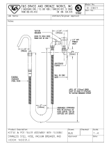
Vacuum Breaker
The vacuum breaker tubing kit can be used with any Series 70 or 1820 pump. The vacuum
breaker is used to break a siphon should the nozzle drop below the fluid level in the tank while the
pump is stuck in the open position. A threaded vacuum breaker, P/N 066570 is shipped installed
in the pump. GASBOY recommends that the vacuum breaker be tubed back to the tank.
The illustration below shows two methods for installing tubing for the vacuum breaker. In all
instances, the vacuum breaker must be tubed (using 1/4" tubing) to the vapor space at the top of
the tank; if the tube is installed below the fluid level of the tank, the ability to break vacuum and
prevent siphoning will be lost. Using the illustrated methods, the tube end may terminate into the
annular vapor space between the 1" suction pipe and the 2" mounting pipe, or into an opening in
the top of the tank. All components shown are provided when you order the kit, P/N 032700.
NOTE: Tubing can be piped to any available opening on top of tank. Use reducer bushings
as required.
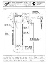
The illustration on the next page shows vacuum breaker tubing for installations where the pump is
installed below the fluid level of the tank. For these installations, the tubing must run directly to
the tank top. The tubing must be horizontal or must slope either toward the pump or the tank so
there are no traps or low spots. Traps or low spots can severely affect vacuum breaker
performance. Tubing length should not exceed eight feet.

GASBOY Series 70 & 1820
2-10 9312
NOTE: Tubing can be piped to any available opening on top of tank. Use reducer bushings
as required.
Testing the Vacuum Breaker
1. Charge tubing completely with fluid.
2. Turn on pump and run for several minutes to purge any air from the system.
3. Turn off pump.
4. With nozzle at ground level and discharging into a container, open nozzle. A small quantity
of fluid (several cups) should drain and then stop.

9312 3-1
Section 3
WIRING
WIRING PRECAUTIONS
The quality of the electrical installation is a major factor in maintaining proper safety levels and
providing trouble-free operation of your GASBOY pump. To assure a quality installation, follow
these rules:
1. Have the pump installed by a competent installer/electrician.
2. All wiring must be installed to conform with all building/fire codes, all Federal, State, and
Local codes, National Electrical Code, (NFPA 70), NFPA 30, Automotive and Marine Service
Station Code (NFPA 30A), and NFPA 395 codes and regulations.
3. Use only threaded, rigid, metal conduit.
4. Use only UL-approved insulated gasoline- and oil-resistant stranded copper wiring of the
proper size.
5. Wire connections should be tightly spliced and secured with a wire nut; close off the open
end of the wire nut with electrical tape.
6. The line to the motor should be on a separate circuit and installed on a 15 AMP breaker.
This should be sufficient for either 115V, 60 cycle or 230V, 50 cycle operation.
7. The unit must be properly grounded.
8. Install an emergency power cutoff if the pump is used for other than personal use. In
addition to circuit breaker requirements of NFPA 70 and NFPA 30A, a single control which
simultaneously removes AC power from all site dispensing equipment is recommended.
This control must be readily accessible, clearly labeled, and in accordance with all local
codes. In order to provide the highest level of safety, we recommend that all employees be
trained as to the location and procedure for turning off power.
9. When DC pulsers are used in the pump, the AC and DC wires must not share any conduits,
junction boxes, or troughs.
CIRCUIT BREAKERS
Power to the unit should be supplied from a dedicated 15 AMP circuit breaker. No other
equipment should be powered from this breaker. This motor draws the following current:
115VAC, 60 cycle, 5.1 amps; 230VAC, 50 cycle, 1.95 amps. If two (2) pumps are supplied from
one breaker, that breaker must be capable of handling the load of both motors. Provisions must
be made to break both legs of any AC circuit.

GASBOY Series 70 & 1820
3-2 9312
GROUNDING
To ensure proper operation of the equipment and provide the necessary safety factors, this unit
must be grounded. A ground wire (preferably green) must be connected between the unit's AC
junction box ground lug and the main electrical service panel. One (1) earth ground connection is
required per unit. The ground rod is to be a solid, corrosion-resistant conductor and must be
installed at the main electrical panel in accordance with the National Electrical Code. It should be
properly tied into the ground bus strip of the panel. We recommend the neutral and ground bus
strips be bonded together (unless prohibited by local codes).
THE PUMP MOTOR
Pumps are shipped from the factory with motors wired for either 115VAC, 60 cycle, or 230VAC,
50 cycle.
The pump motor is equipped with thermal overload protection. If overheated, it will shut itself off
without any damage to the windings. Be sure to turn off the pump power if this occurs. As the
motor cools, it will start without warning if power is on.
WIRE SIZE
The AC wire size of the AC power lines of a pump depends on the voltage at which the pump will
be operated (115/230) and the distance from the circuit breaker panel to the pump. When two
pumps are powered from the same breaker through the same wires, the gauge of the wires
should be increased to handle the added load according to the distance from the breaker panel.
Use the chart below to select the proper wire size for your installation.
Table 3-1. Wire Size
WIRE GAUGE SIZES FOR 1/3 HP MOTOR
DISTANCE
(FEET/METERS)
115 VAC
GAUGE
230 VAC
GAUGE
25’ 7m 14 14
50’ 15m 14 14
100’ 30m 12 12
150’ 46m 10 12
200’ 61m 8 12
250’ 76m 8 12
300’ 91m 8 12
The AC wire size for the reset complete (switch detect) line should be 14 AWG (when it is used).

Wiring
9312 3-3
PULSER WIRING
An optional pulser (available on the Series 1820R only) is used when external monitoring of the
dispensing unit operation is desired. The pulser transmits one electrical signal (pulse) for each
predetermined amount of fuel dispensed. Reed 10:1 pulsers operating with DC voltages are
used. Pulser wiring must be 18AWG and installed in metal conduit separate from all AC wiring. It
cannot share a common junction box, wiring trough or conduit with any AC wiring.
CONDUIT
All wiring to the GASBOY pump must be installed in 1/2" threaded, rigid, metal conduit.
Do
not use knockout boxes and flexible conduit.
If equipped with a DC pulser, AC power wires must be installed in a separate conduit from the DC
pulser and the AC power wires and DC pulser wires must not be run in any sort of common
conduit or trough.
All wiring and conduit runs must also conform with the National Electrical Code (NFPA 70) and the
Automotive and Marine Service Station Code (NFPA 30A). All wiring and conduit runs must
conform to local codes.
The conduit layout drawing on the left is for all Series 70 and 1820 rounded cabinet models. The
drawing on the right is for 1820R models. The junction boxes shown below the 1820R are
supplied with the pump.

GASBOY Series 70 & 1820
3-4 9312
PUMP WIRING DIAGRAMS
115VAC Pumps Series 70 and 1820 (left) and Series 1820R (right)
230VAC Pumps Series 70 and 1820 (left) and Series 1820R (right)
NOTE FOR 230V MOTORS: Some motors may contain different wire colors than those shown. In
this case, Hot is Black, Neutral is White and Aux AC Control is Brown.
1. All wiring and conduit runs must conform with all building/fire codes, all Federal, State, and Local
codes, National Electrical Code, (NFPA 70), NFPA 30, Automotive and Marine Service Station Code
(NFPA 30A), and NFPA 395 codes and regulations.
2. For the Series 70 and Series 1820 rounded cabinet models, make the field wire connections in the
motor junction box. The 1820R models with the squared cabinet come with the wires already
extended through the end of a factory-installed conduit. The 1820R models also come with a junction
box which is to be mounted directly beneath the pump. The field wire connections for the 1820R
models should be made in this junction box (not the pump motor junction box). Wire connections
should be tightly spliced and secured with a wire nut. Close off the end of the wire nut with electrical
tape.
3. The Aux AC Control Lead wire is shipped capped from the factory. When used, it connects to a
solenoid valve or fuel management system. Do not connect this wire without first checking the ON
voltage of this line to ascertain compatibility with the equipment being connected.
4. Pulser wiring must be 18AWG and installed in metal conduit separate from all AC wiring. It cannot
share a common junction box, wiring trough or conduit with any AC wiring.
/