Intel ISP1100 User manual
- Category
- Server/workstation motherboards
- Type
- User manual
This manual is also suitable for

Intel
®
ISP1100 Internet Server
Product Guide
A Guide for Technically Qualified Assemblers of Intel
®
Identified Subassemblies/Products
Order Number: A10528-001

Disclaimer
Intel Corporation (Intel) makes no warranty of any kind with regard to this material, including, but not limited to, the implied
warranties of merchantability and fitness for a particular purpose. Intel assumes no responsibility for any errors that may
appear in this document. Intel makes no commitment to update nor to keep current the information contained in this
document. No part of this document may be copied or reproduced in any form or by any means without prior written consent
of Intel.
An Intel
®
product, when used in accordance with its associated documentation, is "Year 2000 Capable" when, upon
installation, it accurately stores, displays, processes, provides, and/or receives date data from, into, and between the
twentieth and twenty-first centuries, including leap year calculations, provided that all other technology used in combination
with said product properly exchanges date data with it.
†
Third party brands and names are the property of their respective owners.
Copyright © 2000, Intel Corporation.

iii
Contents
1 Description
System Components............................................................................................................ 7
Server Board Features......................................................................................................... 8
Server Board Connectors and Components......................................................................... 9
Controls, Connectors, and Indicators.................................................................................. 10
Front Panel................................................................................................................ 10
Back Panel ................................................................................................................ 10
Processors......................................................................................................................... 11
Memory.............................................................................................................................. 11
Chipset............................................................................................................................... 13
Universal Serial Bus .................................................................................................. 13
IDE Support............................................................................................................... 14
Real-Time Clock, CMOS SRAM, and Battery ............................................................ 14
I/O Controller...................................................................................................................... 15
Serial Ports................................................................................................................ 15
Diskette Drive Controller............................................................................................ 15
Keyboard and Mouse Interface.................................................................................. 16
Hardware Monitor............................................................................................................... 16
SCSI Hard Drive LED Connector........................................................................................ 17
Intel
®
Pro/100+ Server (82559) Ethernet Controllers.......................................................... 17
Wake on LAN.....................................................................................................................17
Wake on Ring/Resume on Ring.......................................................................................... 18
Wake on Ring............................................................................................................ 18
Resume on Ring........................................................................................................ 18
SMI and NMI Routing......................................................................................................... 19
Power Connector................................................................................................................19
Speaker.............................................................................................................................. 19
Fan Support ....................................................................................................................... 20
2 Removing/Installing Server Components
Before You Begin............................................................................................................... 21
FCC/Emissions Disclaimer ........................................................................................ 21
Warnings and Cautions.............................................................................................. 21
Safety and Regulatory Requirements ........................................................................ 24
Safety Compliance..................................................................................................... 24
Electromagnetic Compatibility (EMC)......................................................................... 24
Tools and Supplies Needed................................................................................................ 24
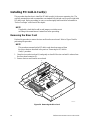
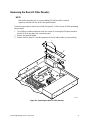
Removing the Server From the Rack.................................................................................. 24
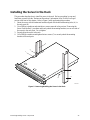
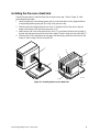
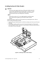
Installing the Server in the Rack......................................................................................... 25
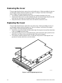
Removing the Cover........................................................................................................... 26
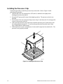
Replacing the Cover........................................................................................................... 26
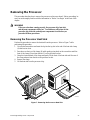
Removing the Processor.................................................................................................... 27
Removing the Processor Heat Sink ........................................................................... 27
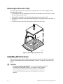
Removing the Processor Chip ................................................................................... 28

iv Intel ISP1100 Internet Server Product Guide
Installing the Processor...................................................................................................... 28
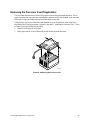
Removing the Processor Fan (If Applicable).............................................................. 29
Installing the Processor Chip ..................................................................................... 30
Installing the Processor Heat Sink............................................................................. 31
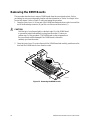
Removing the DIMM Boards............................................................................................... 32
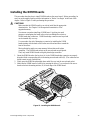
Installing the DIMM Boards................................................................................................. 33
Removing the Hard Drive(s)............................................................................................... 34
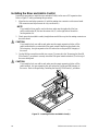
Installing the Hard Drive(s)................................................................................................. 35
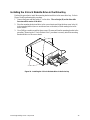
Installing the Hard Drive in the Mounting Bracket....................................................... 35
Installing the Hard Drive in the Drive Bay................................................................... 36
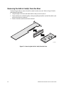
Removing the 3.5-inch Diskette Drive................................................................................. 37
Installing the 3.5-inch Diskette Drive................................................................................... 38
Installing the Drive in the Mounting Bracket............................................................... 38
Installing the 3.5-inch Diskette Drive in the Drive Bay................................................ 39
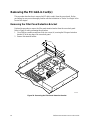
Removing the PCI Add-in Card(s) ...................................................................................... 40
Removing the Filler Panel Retention Bracket............................................................. 40
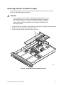
Removing the Riser and Add-in Card(s) .................................................................... 41
Removing the Add-in Card(s) From the Riser............................................................ 42
Installing the Rear I/O Filler Panel(s) ......................................................................... 43
Installing PCI Add-in Card(s).............................................................................................. 44
Removing the Riser Card........................................................................................... 44
Installing the Add-in Card(s) on the Riser................................................................... 46
Removing the Rear I/O Filler Panel(s) ....................................................................... 47
Installing the Riser and Add-in Card(s) ...................................................................... 48
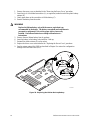
Replacing the Back-up Battery........................................................................................... 49
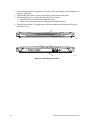
Power Up the Server.......................................................................................................... 51
Power Cord Requirements......................................................................................... 51
3 Configuration Software and Utilities
Hot Keys............................................................................................................................. 54
Power-On Self-Test (POST)............................................................................................... 54
Using BIOS Setup.............................................................................................................. 55
Main Menu................................................................................................................. 56
Advanced Menu......................................................................................................... 57
Security Menu............................................................................................................ 60
Boot Menu................................................................................................................. 60
System Management Menu....................................................................................... 62
Exit Menu................................................................................................................... 63
Upgrading the BIOS........................................................................................................... 63
Preparing for the Upgrade ......................................................................................... 63
Performing the Upgrade............................................................................................. 65
Recovering the BIOS................................................................................................. 65
4 Solving Problems
Resetting the System ......................................................................................................... 68
Initial System Startup..........................................................................................................68
Checklist.................................................................................................................... 68
Running New Application Software..................................................................................... 69
Checklist.................................................................................................................... 69

Contents v
After the System Has Been Running Correctly................................................................... 69
Checklist.................................................................................................................... 69
More Problem Solving Procedures..................................................................................... 70
Preparing the System for Diagnostic Testing............................................................. 70
Monitoring POST....................................................................................................... 70
Verifying Proper Operation of Key System Lights ...................................................... 70
Confirming Loading of the Operating System............................................................. 70
Specific Problems and Corrective Actions.......................................................................... 71
Power Light Does Not Light....................................................................................... 71
No Characters Appear on Screen.............................................................................. 71
Characters Are Distorted or Incorrect......................................................................... 72
System Cooling Fans Do Not Rotate Properly........................................................... 72
Diskette Drive Activity Light Does Not Light............................................................... 72
Hard Disk Drive Activity Light Does Not Light ............................................................ 73
CD-ROM Drive Activity Light Does Not Light ............................................................. 73
Cannot Connect to a Server....................................................................................... 73
Problems with Network.............................................................................................. 74
Problems with Application Software.................................................................................... 74
Bootable CD-ROM Is Not Detected.................................................................................... 75
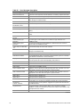
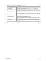
Error and Informational Messages...................................................................................... 75
Error Codes and Error Messages....................................................................................... 75
Index...................................................................................................................................... 78
Figures
1. System Components ................................................................................................... 7
2. Server Board Connectors and Components ................................................................ 9
3. Front Panel Controls, Connectors, and Indicators...................................................... 10
4. Back Panel Connectors............................................................................................. 10
5. Removing/Installing the Server in the Rack ............................................................... 25
6. Removing/Replacing the Cover................................................................................. 26
7. Removing the Processor Heat Sink........................................................................... 27
8. Removing the Processor Chip................................................................................... 28
9. Removing the Processor Fan .................................................................................... 29
10. Installing the Processor Chip..................................................................................... 30
11. Installing the Processor Heat Sink............................................................................. 31
12. Removing the DIMM Boards...................................................................................... 32
13. Installing the DIMM Boards........................................................................................ 33
14. Removing the Hard Drive(s) ...................................................................................... 34
15. Installing the Hard Drive in the Mounting Bracket ...................................................... 35
16. Installing the Hard Drive in the Drive Bay................................................................... 36
17. Removing the 3.5-inch Diskette Drive........................................................................ 37
18. Installing the 3.5-inch Diskette Drive in the Mounting Bracket.................................... 38
19. Installing the 3.5-inch Diskette Drive in the Drive Bay................................................ 39
20. Removing the Filler Panel Retention Bracket............................................................. 40
21. Removing the Riser and Add-in Card(s) .................................................................... 41
22. Removing the Add-in Card(s) from the Riser ............................................................. 42
23. Installing the Rear I/O Filler Panel(s)......................................................................... 43
24. Removing the Riser Card........................................................................................... 44

vi Intel ISP1100 Internet Server Product Guide
25. Installing the Add-in Card(s) on the Riser .................................................................. 46
26. Removing the Rear I/O Filler Panel(s)....................................................................... 47
27. Installing the Riser and Add-in Card(s) ...................................................................... 48
28. Replacing the Lithium Back-up Battery...................................................................... 50
29. Powering Up the Server............................................................................................. 52
Tables
1. Server Board Features ................................................................................................ 8
2. Supported Processors............................................................................................... 11
3. Supported Memory Characteristics............................................................................ 12
4. Memory Error Detection Mode................................................................................... 12
5. Fan Tachometer MUX Control Mapping..................................................................... 16
6. SMI and NMI Routing ................................................................................................ 19
7. Fan Connector Descriptions ...................................................................................... 20
8. Configuration Utilities................................................................................................. 54
9. Hot Keys.................................................................................................................... 54
10. BIOS Setup Menu Bar............................................................................................... 55
11. BIOS Setup Function Keys........................................................................................ 55
12. Main Menu................................................................................................................. 56
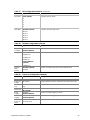
13. Advanced Menu......................................................................................................... 57
14. Boot Configuration Submenu..................................................................................... 57
15. Peripheral Configuration Submenu............................................................................ 57
16. IDE Configuration Menu ............................................................................................ 58
17. IDE Configuration Submenu...................................................................................... 58
18. Diskette Configuration Submenu............................................................................... 59
19. Event Log Configuration Submenu............................................................................ 59
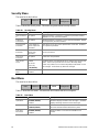
20. Security Menu............................................................................................................ 60
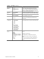
21. Boot Menu................................................................................................................. 60
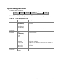
22. System Management Menu....................................................................................... 62
23. Exit Menu .................................................................................................................. 63
24. Beep Codes............................................................................................................... 75
25. Error Messages Description....................................................................................... 76

7
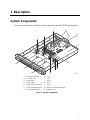
1 Description
System Components
Figure 1 shows the location of the major system components in the Intel
®
ISP1100 Internet Server.
B
C
M
D
A
OMO9445
E
H
L
K
N
F
G
J
I
A. PCI Add-in Card Slots H. Fan 1
B. PCI Riser Card I. Fan 2
C. Server Board J. Fan 3
D. Power Supply K. Fan 4
E. 1-Inch Hard Drive Bracket L. Fan 5
F. 1-Inch Hard Drive Bracket M. Add-In Card Retention Bracket
G. 3.5-Inch Diskette Drive
N. DIMM Sockets
Figure 1. System Components

8 Intel ISP1100 Internet Server Product Guide
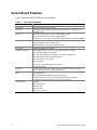
Server Board Features
Table 1 summarizes the TR440BX server board features.
Table 1. Server Board Features
Feature Description
Form Factor MicroATX (9.6 inches by 9.6 inches)
Processor Supports an Intel
®
Pentium
®
III processor or Intel Celeron
™
processor in a
PGA370 socket.
Memory Four 168-pin dual in-line memory module (DIMM) sockets
Support unbuffered and registered SDRAM DIMMs
Supports up to 1 GB of ECC, SPD SDRAM with registered or unbuffered DIMMs
Chipset Intel
®
82440BX AGPset, consists of:
Intel
®
82443BX PCI/AGP controller (PAC)
Intel
®
82371EB PCI ISA IDE Xcelerator (PIIX4E)
I/O Control SMSC FDC37B807 I/O controller
Peripheral Interfaces Two integrated Intel
®
Pro/100+ Server
(
82559) Ethernet controllers
One standard diskette drive interface
One high-density diskette drive interface for slim-line diskette drive
Two IDE interfaces with Ultra DMA/33 support
Two serial ports (1 rear, 1 front)
Two USB ports
Two PS/2
†
interfaces for keyboard and mouse
LED panel interface
Expansion One PCI bus in combination with a 2x11 riser sideband connector supports a
passive dual-slot PCI riser card (32 bit/33 MHz)
BIOS Intel
®
/AMI BIOS
Intel
®
E28F008S585 8-Mbit boot block flash memory
Supports SMBIOS, Advanced Power Management (APM), Advanced
Configuration and Power Interface (ACPI), and Plug and Play
Other Features Speaker
Hardware monitor
Wake on Ring
Wake on LAN
†
SCSI LED connector

Description 9
Server Board Connectors and Components
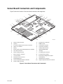
Figure 2 shows the locations of the server board connectors and components.
ABC
DE
FGH
J
I
K
L
M
N
O
P
Q
R
S
T
U
V
W
X
Y
Z
AA
OMO9446
A. Wake on LAN Connector O. System Fans Connectors
B. Speaker P. DIMM Sockets
C. PCI Riser Sideband and PCI Bus Connectors Q. Front Panel Connector
D. SMSC I/O Controller R. Front Panel Controller
E. Battery S. Primary IDE Connector
F. Intel Pro/100+ Server (82559) Ethernet Controllers T. Intel 82371EB PIIX4E
G. SCSI LED Connector U. Gluechip
H. Wake on Ring Connector V. Secondary IDE Connector
I. Back Panel I/O Connectors W. Password Clear Jumper
J. Clock Generator X. BIOS Setup Configuration Jumper
K. PGA370 Processor Socket Y. Flash Memory
L. Intel 82443BX PAC Z. Diskette Drive Connector
M. Heceta 2 Hardware Monitor Controller AA. High-Density Diskette Drive Connector
N. Power Supply Connector
Figure 2. Server Board Connectors and Components

10 Intel ISP1100 Internet Server Product Guide
Controls, Connectors, and Indicators
Front Panel
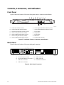
Figure 3 shows the locations of the server front-panel controls, connectors, and indicators.
DCA
OMO9447
BEFGHI
J
KL
M
N
A. Power LED Indicator (Green)
H. User-Programmable LED Indicator (Green)
B. System Fault LED Indicator (Amber)
I. User-Programmable LED Indicator (Green)
C. Hard Drive Activity LED Indicator (Green)
J. Power Switch
D. LAN 1 Activity LED Indicator (Yellow)
K. Sleep Switch
E. LAN 1 100 Mbps LED Indicator (Green)
L. Reset Switch
F. LAN 2 Activity LED Indicator (Yellow)
M. NMI Switch
G. LAN 2 100 Mbps LED Indicator (Green)
N. Serial Port B Connector
Figure 3. Front Panel Controls, Connectors, and Indicators
Back Panel
Figure 4 shows the locations of the server back-panel connectors.
A
B
C
D
E
FG
OMO9448
A. AC Power Input Connector E. LAN 2 Connector
B. PS/2 Keyboard/Mouse Connectors F. LAN 1 Connector
C. USB Port 0 Connector G. Serial Port A Connector
D. USB Port 1 Connector
Figure 4. Back Panel Connectors

Description 11
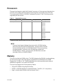
Processors
The server board supports a single Intel Pentium III processor or Celeron processor that plugs into a
PGA370 socket connector that secures the processor chip with a zero-insertion-force (ZIF) arm.
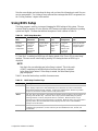
The host bus speed (66 MHz or 100 MHz) is automatically selected. Table 2 lists the processors
supported by the server board.
Table 2. Supported Processors
Processor Type L2 Cache Size FSB Speed Speed
Celeron processor 128 KB 66 MHz
566 MHz
1
533 MHz
500 MHz
466 MHz
433 MHz
400 MHz
366 MHz
Pentium III processor 256 KB 100 MHz 750 MHz
700 MHz
650 MHz
600E MHz
550E MHz
500 MHz
1
Coppermine 128 KB; other Intel Celeron processors are based on Mendocino core.
NOTE
The server board supports Pentium III processors with a 100 MHz host bus
and Celeron processors with a 66 MHz host bus. Processors with a 100 MHz
host bus should be used only with 100 MHz SDRAM. The server board may
not operate reliably if a processor with a 100 MHz host is paired with
66 MHz SDRAM. However, processors with a 66 MHz host can be used
with either 66 MHz or 100 MHz SDRAM.
Memory
The server board has four DIMM sockets. The BIOS determines the SDRAM size and speed using
the serial presence detect (SPD) data structure programmed into an EEPROM on the DIMM.
Memory size is 16 MB to 1 GB. DIMM board memory size can be mixed but must be either all
unbuffered or registered. Slot vacancies are allowed.
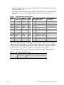
The server board supports the following memory features:
• 168-pin SPD DIMMs with gold-plated contacts.
• 66 MHz or 100 MHz unbuffered or registered SDRAM, 72-bit ECC, 3.3 V only memory.
• Single- or double-sided DIMMs in the sizes listed in Table 3.

12 Intel ISP1100 Internet Server Product Guide
• Unbuffered DIMMs of the following sizes: 16 MB, 32 MB, 64 MB, 128 MB and 256 MB for a
total memory size of 1 GB.
• Registered DIMMs of the following sizes: 64MB, 128Mb and 256MB for a maximum memory
size of 1 GB. Only non-stacked DIMMs are supported because of a server board space
constraint.
Table 3. Supported Memory Characteristics
DIMM
Size Configuration
DRAM
Technology
DRAM
Depth
DRAM
Width
Single-sided DIMM
(Size x 64 Bit)
Double-sided DIMM
(Size x 64 Bit)
16 MB 2 Mbit x 72 16 Mbit 2 Mbit 8 bit 2 MB x 8 B = 16 MB
32 MB 4 Mbit x 72 16 Mbit 2 Mbit 8 bit 4 MB x 8 B = 32 MB
32 MB 4 Mbit x 72 16 Mbit 4 Mbit 4 bit 4 MB x 8 B = 32 MB
64 MB 8 Mbit x 72 16 Mbit 4 Mbit 4 bit 8 MB x 8 B = 64 MB
32 MB 4 Mbit x 72 64 Mbit 4 Mbit 16 bit 4 MB x 8 B = 32 MB
64 MB 8 Mbit x 72 64 Mbit 4 Mbit 16 bit 8 MB x 8 B = 64 MB
64 MB 8 Mbit x 72 64 Mbit 8 Mbit 8 bit 8 MB x 8 B = 64 MB
128 MB 16 Mbit x 72 64 Mbit 8 Mbit 8 bit 16 MB x 8 B = 128 MB
128 MB 16 Mbit x 72 64 Mbit 16 Mbit 4 bit 16 MB x 8 B = 128 MB
64 MB 8 Mbit x 72 128 Mbit 8 Mbit 16 bit 8 MB x 8 B = 64MB
128 MB 16 Mbit x 72 128 Mbit 8 Mbit 16 bit 16 MB x 8 B = 128 MB
128 MB 16 Mbit x 72 128 Mbit 16 Mbit 8 bit 16 MB x 8 B = 128 MB
256 MB 32 Mbit x 72 128 Mbit 16 Mbit 8 bit 32 MB x 8 B = 256 MB
When ECC memory is installed, the BIOS supports both ECC and non-ECC mode. ECC mode is
enabled in the BIOS Setup program. The BIOS automatically detects if ECC memory is installed
and provides the Setup option for selecting the ECC mode. If any non-ECC memory is installed,
the Setup option for ECC mode does not appear and ECC operation is not available.
Table 4 describes the effect of using Setup to put each memory type in each supported mode.
Table 4. Memory Error Detection Mode
DIMM Type ECC Disabled ECC Enabled
ECC No error detection Single-bit error correction, multiple-bit error detection
Non-ECC No error detection N/A

Description 13
NOTE
All memory components used with the server board should comply with the
following PC SDRAM specifications (see Chapter 13 in the Intel
®
ISP1100
Internet Server Technical Product Specification for information about how to
obtain these specifications):
• PC SDRAM Specification (memory component specific)
• PC Unbuffered SDRAM Specifications
• PC Serial Presence Detection Specification
Processors with 100 MHz host bus speed must be paired only with 100 MHz
SDRAM. Processors with 66 MHz host bus speed can be paired with either
66 MHz or 100 MHz SDRAM.
Chipset
The Intel 82440BX AGPset consists of the Intel 82443BX PAC and the Intel 82371EB PIIX4E
bridge chip. The PAC provides an optimized DRAM controller. The PAC’s accelerated graphics
port (AGP) interface is not used. The I
/O subsystem of the 82440BX is based on the PIIX4E,
which is a highly integrated PCI ISA IDE Xcelerator Bridge.
Universal Serial Bus
The server board has two universal serial bus (USB) ports that accommodate one USB peripheral
connected to each port. For more than two USB devices, an external hub can be connected to either
port. The two USB ports are implemented with stacked back panel I/O connectors. The server
board fully supports UHCI and uses UHCI-compatible software drivers. See Chapter 13 in the Intel
ISP1100 Internet Server Technical Product Specification for information about the USB and UHCI
specifications.
The USB includes the following capabilities:
• Self-identifying peripherals that can be plugged in while the computer is running.
• Automatic mapping of function to driver and configuration.
• Support for synchronous and asynchronous transfer types over the same set of wires.
• Guaranteed bandwidth and low latencies appropriate for telephony, audio, and other
applications.
• Error-handling and fault-recovery mechanisms built into the protocol.
NOTE
Computer systems that have an unshielded cable attached to a USB port may
not meet FCC Class B requirements; even if no device or a low-speed USB
device is attached to the cable. Use shielded cable that meets the
requirements for full-speed devices.

14 Intel ISP1100 Internet Server Product Guide
IDE Support
The server board has two independent bus-mastering IDE interfaces that support:
1. ATAPI devices (such as CD-ROM drives).
2. ATA devices using the transfer modes listed in the Intel ISP1100 Internet Server Technical
Product Specification.
The BIOS supports logical block addressing (LBA) and extended cylinder head sector (ECHS)
translation modes. The drive reports the transfer rate and translation mode to the BIOS.
The server board supports PCMCIA ATA Type II flash card technology through its IDE interfaces.
No special driver is needed for a PCMCIA ATA Type II flash drive since most operating systems
see it as standard IDE drive.
Real-Time Clock, CMOS SRAM, and Battery
The real-time clock is compatible with DS1287 and MC146818 components. The clock provides a
time-of-day clock and a multi-century calendar with alarm features and century rollover. The real-
time clock supports 256 bytes of battery-backed CMOS SRAM in two banks that are reserved for
BIOS use.
A coin-cell Lithium battery powers the real-time clock and CMOS memory. When the computer is
not plugged into an AC power source, the battery has an estimated life of three years. When the
computer is plugged into an AC power source, the 3.3 V standby current from the power supply
extends the life of the battery. The clock is accurate to ±13 minutes/year at 25ºC with 3.3 V
standby applied.
The time, date, and CMOS values can be specified and the CMOS values can be returned to their
defaults in the BIOS Setup program.
NOTE
The recommended method for accessing the date in systems with Intel server
boards is indirectly from the real-time clock (RTC) via the BIOS. The BIOS
on the server board contains a century checking and maintenance feature that
checks the two least significant digits of the year stored in the RTC during
each BIOS request (INT 1Ah) to read the date. If the year is less than 80
(when 1980 is the first year supported by the PC), the BIOS updates the
century byte to 20 which enables operating systems and applications that use
the BIOS date/time services to reliably manipulate the year as a four-digit
value.
For more information on a proper date access in systems with Intel server
boards, please see: http://support.intel.com/support/year2000/

Description 15
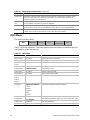
I/O Controller
The FDC37B807 I/O controller from SMSC is an ISA Plug and Play-compatible, multifunctional
I/O device that provides the following features (see Chapter 13 in the Intel ISP1100 Internet Server
Technical Product Specification for Plug and Play specification information):
• Two serial ports.
• Interface for one 1.2 MB, 1.44 MB, or 2.88 MB diskette drive.
• Three-mode diskette drive support (driver required).
• FIFO support on both serial and diskette drive interfaces.
• One parallel port with extended capabilities port (ECP) and enhanced parallel port (EPP)
support.
• PS/2-style mouse and keyboard interfaces.
• Support for serial IRQ packet protocol.
• Intelligent power management, including:
Shadowed write-only registers for ACPI compliance.
Programmable wake up event interface.
The BIOS Setup program provides configuration options for the I/O controller.
Serial Ports
The server board has two 9-pin D-Sub serial port connectors; one on the back panel and one on the
front panel under the bezel. The front-panel serial port is connected in parallel with the serial port
B D-Sub connector located on the back panel. The serial port NS16C550-compatible UARTs
support data transfers at speeds up to 115.2 Kbits/sec with BIOS support. The serial ports can be
assigned as COM1 (3F8h), COM2 (2F8h), and COM3 (3E8h).
Diskette Drive Controller
The I/O controller supports a single diskette drive that is compatible with the 82077-diskette drive
controller and supports both PC-AT
†
and PS/2 modes. In the Setup program, the diskette driver
interface can be configured for the following capacities and sizes:
• 360 KB, 5.25-inch
• 1.2 MB, 5.25-inch
• 720 KB, 3.5-inch
• 1.2 MB, 3.5-inch (driver required)
• 1.25/1.44 MB, 3.5-inch
• 2.88 MB, 3.5-inch
NOTE
The I/O controller supports 1.2 MB, 3.5-inch diskette drives, but a special
driver is required (three-mode).

16 Intel ISP1100 Internet Server Product Guide
Keyboard and Mouse Interface
The PS/2 keyboard and mouse connectors are located on the server back panel. The +5 V lines to
these connectors are protected with a PolySwitch
†
circuit that, like a self-healing fuse, reestablishes
the connection after an overcurrent condition is removed.
The keyboard controller contains the AMI keyboard and mouse controller code, provides the
keyboard and mouse control functions, and supports password protection for power on/reset. A
power on/reset password can be specified in the BIOS Setup.
The keyboard controller also supports the hot-key sequence <Ctrl><Alt><Del> for a software
reset. This key sequence resets the computer software by jumping to the beginning of the BIOS
code and running the Power-On Self-Test (POST).
NOTE
The mouse and keyboard can be plugged into either of the PS/2 connectors.
Turn off AC power to the computer before a keyboard or mouse is connected
or disconnected.
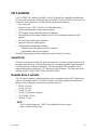
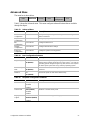
Hardware Monitor
A Heceta 2 system monitor controller is provided on the server board to monitor temperature,
voltage, fan speed and a temperature sensor located on the front panel. Temperature is monitored
through a sensor internal to the Heceta 2 that indicates the ambient temperature of the area of the
board in which the Heceta 2 IC is located. The Heceta 2 monitors +5V, +3.3V, +12V, –12V,
+1.5V, and the processor core voltage. The Heceta 2 may be used to monitor the speed of a fan that
has a tachometer output connected to any of the five auxiliary fan connectors. The five system fan
tachometer outputs are multiplexed to the Heceta 2 device to allow individual monitoring. The
software through the PIIX4 chip controls the multiplexing of the fan tachometer outputs to the
Heceta 2 chip. The multiplexer control bits (FAN_MUXCTL0 and FAN_MUXCTL1) are
connected to the PIIX4 are connected to the outputs GPO0 and GPO13, respectively. Table 5
shows the fan tachometer mapping.
Table 5. Fan Tachometer MUX Control Mapping
Fan_MUXCTL0 Fan_MUXCTL1 Heceta FAN1_TACH Input Heceta FAN2_TACH Input
0 0 Fan 1 (J35) Fan 4 (J38)
0 1 Fan 2 (J34) Fan 5 (J37)
1 0 Fan 3 (J33) NONE
1 1 NONE NONE
The Heceta 2 is set up and interfaced through the PIIX4 SMBUS interface. Out of band or absolute
thresholds may be set for many of the monitored functions using the SMBUS interface. Threshold
faults are available by polling the Heceta 2 via the SMBUS interface. The Heceta 2 updates its
information approximately every 1 second.

Description 17
For more details on programming and reading the Heceta 2 chip please refer to the Heceta 2 Device
Specification version 1.2 or later (see Chapter 13 in the Intel ISP1100 Internet Server Technical
Product Specification for how to obtain this specification).
SCSI Hard Drive LED Connector
The optional SCSI hard drive LED connector is a 1 x 2-pin connector that allows add-in SCSI
controller applications to use the same LED as the IDE controller. This connector can be connected
to the LED output of the add-in controller card (see Chapter 13 in the Intel ISP1100 Internet Server
Technical Product Specification for the location and pinouts of the SCSI hard drive LED
connector).
Intel
®
Pro/100+ Server (82559) Ethernet Controllers
Two Intel Pro/100+ Server (82559) Ethernet controllers provide two 10/100 Base-T interfaces
accessible from the back panel (see Chapter 13 in the Intel ISP1100 Internet Server Technical
Product Specification for the location and pinouts of the LAN connectors).
The LAN connectors on the back panel do not provide LEDs to indicate transmit/receive activity
and speed. Instead, these indicators are routed to four LEDs on the front panel. See “Controls,
Connectors, and Indicators” for LED locations and definitions.
Alert on LAN and Wake on LAN features are supported by the TR440BX server board software
and the SMBUS interface of the Intel 82559s. See the BIOS specification for information
regarding Alert on LAN and Wake on LAN. Also see “Wake on LAN” for more information.
CAUTION
For Wake on LAN, the 5V standby line for the power supply must be capable
of delivering +5V ±5% at 720 mA. Failure to provide adequate standby
current, when implementing Wake on LAN can damage the power supply.
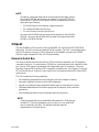
Wake on LAN
Wake on LAN enables remote wakeup of the computer through a network. If a PCI add-in network
interface card (NIC) with remote wakeup capabilities is desired, the remote wakeup connector on
the NIC must be connected to the onboard Wake on LAN connector.
The integrated LAN controllers or the add-in NIC monitors network traffic at the MII interface.
Upon detecting a Magic Packet, the LAN controllers or NIC assert a wakeup signal that powers up
the computer.
To access this feature, use the optional Wake on LAN connector on the server board. See “Server
Board Connectors and Components” for the location and definition of the Wake on LAN connector.

18 Intel ISP1100 Internet Server Product Guide
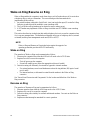
Wake on Ring/Resume on Ring
Wake on Ring enables the computer to wake from sleep or soft-off mode when a call is received on
a telephony device, such as a faxmodem. The server board provides three methods for
implementing Wake on Ring:
1. An external modem connected to Serial Port A (rear) can toggle the super I/O controller’s Ring
Indicator pin which should be enabled to cause a wakeup event.
2. The 2-pin Wake on Ring header may be shorted to cause a wakeup event.
3. A PCI modem may implement a Wake on Ring circuit that uses PCI PME# to cause a wakeup
event.
This section describes two technologies that enable telephony devices to access the computer when
it is in a power-managed state. The method used depends on the type of telephony device (external
or internal) and the power management mode used (APM or ACPI).
NOTE
Wake on Ring and Resume on Ring technologies require the support of an
operating system that provides full ACPI functionality.
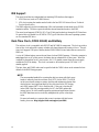
Wake on Ring
The operation of Wake on Ring can be summarized as follows:
1. Powers up the computer from either the APM soft-off mode or the ACPI S5 state.
2. Requires two calls to access the computer:
• First call powers up the computer.
• Second call enables access (when the appropriate software is loaded).
3. Detects incoming call differently for external as opposed to internal modems:
• For external modems, server-board hardware monitors the ring indicate (RI) input of serial
port A and B.
• For internal modems, a cable must be routed from the modem to the Wake on Ring
connector.
See “Server Board Connectors and Components” for the location and definition of the Wake on
Ring connector.
Resume on Ring
The operation of Resume on Ring can be summarized as follows:
1. Resumes operation from either the APM sleep mode or the ACPI S1 state.
2. Requires only one call to access the computer.
3. Detects incoming calls similarly for external and internal modems. Does not use the Wake on
Ring connector.
4. Requires modem interrupt be unmasked for correct operation.

Description 19
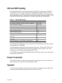
SMI and NMI Routing
There are numerous SMI sources and all are routed to the PIIX4. Software must configure the
PIIX4 SMI source pins to control whether SMI is propagated through to the processor via its
H_SMI input or not. For details on the fault conditions that cause SMI to occur, consult the data
sheets of the SMI source ICs. The SMI routing on the server board is described in Table 6. Note
that some PIIX4 inputs have several sources. Schematic signal names are in parenthesis.
Table 6. SMI and NMI Routing
SMI Source PIIX4 Input Pin
BX Chipset PCI SERR# - used for ECC Errors (P_SERR#) EXT_SMI#
LAN PCI SERR# (P_SERR#) EXT_SMI#
All three PCI Slot’s SERR# (P_SERR#) EXT_SMI#
Gluechips EXTSMI# output – used for +5 VSB errors GPI13
Gluechips EXTSMI# output – Through buffer to (P_SERR#) EXT_SMI#
LAN1 PCI PME# (P_PME#) GPI1
LAN2 PCI PME# (P_PME#) GPI1
All three PCI slot’s PME# (P_PME#) GPI1
Super I/O Serial Interrupt SMI – used for watchdog timer
(SER_IRQ)
SER_IRQ
Super I/O PME# (SIO_RIA#) – originally from WOR header or
ext. modem
RIAB
Wake on LAN header – used for Wake on LAN (WOL#) LID
The Gluechips EXT_SMI# output is also connected to the PIIX4 GPI13 pin to provide a status of
the Gluechips EXT_SMI# signal.
All NMI generation on the server board is under software control. Writes to PIIX4 GPO17 are
routed to the PIIX4 IOCHK# input which may be configured to cause a NMI to occur. Thus,
software may cause a NMI to occur by pulsing GPO17 active.
The TR440BX server board BIOS SMI handler detects SMI events, logs the events, and elevates
selected events to NMI level.
Power Connector
When used with an ATX-compliant power supply that supports remote power on/off, the server
board can turn off the system power through software control.
Speaker
A 47-ohm inductive speaker is mounted on the server board. The speaker provides audible error
code (beep code) information during the Power-On Self-Test (POST).

20 Intel ISP1100 Internet Server Product Guide
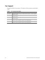
Fan Support
The server board has five fan connectors. The functions of the fan connectors are described in
Table 7.
Table 7. Fan Connector Descriptions
Connector Function
Fan 1 (J35) Supports fan speed sensing for fans with tachometer outputs. Connector supports
variable fan speed.
Fan 2 (J34) Supports fan speed sensing for fans with tachometer outputs. Connector supports
variable fan speed.
Fan 3 (J33) Supports fan speed sensing for fans with tachometer outputs. Connector supports
variable fan speed.
Fan 4 (J38) Supports fan speed sensing for fans with tachometer outputs. Connector supports
on/off fan control or variable fan speed via a fuse-stuffing option.
Fan 5 (J37) Supports fan speed sensing for fans with tachometer outputs. Connector supports
on/off fan control or variable fan speed via a fuse-stuffing option.
Page is loading ...
Page is loading ...
Page is loading ...
Page is loading ...
Page is loading ...
Page is loading ...
Page is loading ...
Page is loading ...
Page is loading ...
Page is loading ...
Page is loading ...
Page is loading ...
Page is loading ...
Page is loading ...
Page is loading ...
Page is loading ...
Page is loading ...
Page is loading ...
Page is loading ...
Page is loading ...
Page is loading ...
Page is loading ...
Page is loading ...
Page is loading ...
Page is loading ...
Page is loading ...
Page is loading ...
Page is loading ...
Page is loading ...
Page is loading ...
Page is loading ...
Page is loading ...
Page is loading ...
Page is loading ...
Page is loading ...
Page is loading ...
Page is loading ...
Page is loading ...
Page is loading ...
Page is loading ...
Page is loading ...
Page is loading ...
Page is loading ...
Page is loading ...
Page is loading ...
Page is loading ...
Page is loading ...
Page is loading ...
Page is loading ...
Page is loading ...
Page is loading ...
Page is loading ...
Page is loading ...
Page is loading ...
Page is loading ...
Page is loading ...
Page is loading ...
Page is loading ...
Page is loading ...
Page is loading ...
Page is loading ...
-
 1
1
-
 2
2
-
 3
3
-
 4
4
-
 5
5
-
 6
6
-
 7
7
-
 8
8
-
 9
9
-
 10
10
-
 11
11
-
 12
12
-
 13
13
-
 14
14
-
 15
15
-
 16
16
-
 17
17
-
 18
18
-
 19
19
-
 20
20
-
 21
21
-
 22
22
-
 23
23
-
 24
24
-
 25
25
-
 26
26
-
 27
27
-
 28
28
-
 29
29
-
 30
30
-
 31
31
-
 32
32
-
 33
33
-
 34
34
-
 35
35
-
 36
36
-
 37
37
-
 38
38
-
 39
39
-
 40
40
-
 41
41
-
 42
42
-
 43
43
-
 44
44
-
 45
45
-
 46
46
-
 47
47
-
 48
48
-
 49
49
-
 50
50
-
 51
51
-
 52
52
-
 53
53
-
 54
54
-
 55
55
-
 56
56
-
 57
57
-
 58
58
-
 59
59
-
 60
60
-
 61
61
-
 62
62
-
 63
63
-
 64
64
-
 65
65
-
 66
66
-
 67
67
-
 68
68
-
 69
69
-
 70
70
-
 71
71
-
 72
72
-
 73
73
-
 74
74
-
 75
75
-
 76
76
-
 77
77
-
 78
78
-
 79
79
-
 80
80
-
 81
81


Intel ISP1100 User manual
- Category
- Server/workstation motherboards
- Type
- User manual
- This manual is also suitable for
Ask a question and I''ll find the answer in the document
Finding information in a document is now easier with AI
Related papers
-
Intel S845WD1-E - Server Board Motherboard User manual
-
-
-
-
-
-
-
-
-
Other documents
-
 micronPC Millennia XP+ User manual
-
Viglen L440GX+ User manual
-
-
American Megatrends AMIDiag 6.12 User guide
-
-
-
Gateway E-3200 User manual
-
NEC Express5800/ES1400 User guide
-
-
Nortel Networks EMC User manual
