
ASSEMBLY MANUAL / OWNER’S MANUAL
Manual en Español Latino Americano:
http://www.schwinnfitness.com

2
Important Safety Instructions - Assembly 3
Safety Warning Labels / Serial Number 4
Specifications 4
Before Assembly 5
Parts 6
Hardware 7
Tools 7
Assembly 8
Leveling the Bike 14
Moving the Bike 14
Important Safety Instructions - Owner’s 15
Features 16
Console Features 17
Contact Heart Rate (CHR) 18
Operations 20
Adjustments 20
Quick Start / Manual Program 20
Profile Programs 21
Pausing or Stopping 21
Results 21
Changing Unit Measures
(English Imperial/Metric) 21
Maintenance 22
Troubleshooting 25
Warranty 27
Nautilus, Inc., (800) NAUTILUS / (800) 628-8458, www.NautilusInc.com - Customer Service: North America (800) 605-3369,
[email protected] | outside U.S. +01-360-859-5180, [email protected] | Printed in China | © 2012 Nautilus, Inc.
TABLE Of CONTENTS
To validate warranty support, keep the original proof of purchase and record the following information:
Serial Number __________________________
Date of Purchase ____________________
To register your product warranty , go to: www.SchwinnFitness.com/register
Or call 1 (800) 605–3369.
If you have questions or problems with your product, please call 1 (800) NAUTILUS (628–8458)
Or go to: www.SchwinnFitness.com

3
IMpORTANT SAfETY INSTRUCTIONS
— ASSEMBLY
!
This icon means a potentially hazardous situation which, if not avoided, could result in death or serious injury.
Obey the following warnings:
!
Read and understand all warnings on this machine.
Carefully read and understand the Assembly instructions.
• Keepbystandersandchildrenawayfromtheproductyouareassemblingatalltimes.
• Donotconnectpowersupplytothemachineuntilinstructedtodoso.
• Donotassemblethismachineoutdoorsorinawetormoistlocation.
• Makesureassemblyisdoneinanappropriateworkspaceawayfromfoottrafcandexposuretobystanders.
• Somecomponentsofthemachinecanbeheavyorawkward.Useasecondpersonwhendoingtheassemblysteps
involvingtheseparts.Donotdostepsthatinvolveheavyliftingorawkwardmovementsonyourown.
• Setupthismachineonasolid,level,horizontalsurface.
• Donottrytochangethedesignorfunctionalityofthismachine.Thiscouldcompromisethesafetyofthismachine
and will void the warranty.
• Ifreplacementpartsarenecessary,useonlygenuineNautilus
®
replacement parts and hardware. Failure to use
genuine replacement parts can cause a risk to users, keep the machine from operating correctly and void the
warranty.
• Donotuseuntilthemachinehasbeenfullyassembledandinspectedforcorrectperformanceinaccordancewiththe
Manual.
• ReadandunderstandthecompleteManualsuppliedwiththismachinebeforerstuse.KeeptheManualforfuture
reference.
• Doallassemblystepsinthesequencegiven.Incorrectassemblycanleadtoinjuryorincorrectfunction.
• Thisproductcontainsmagnets.Magneticeldscaninterferewiththenormaluseofcertainmedicaldevicesataclose
range.Usersmaycomeintoproximityofthemagnetsintheassembly,maintenance,and/oruseoftheproduct.Given
the obvious importance of these devices, such as a pacemaker, it is important that you consult with your medical
provider in connection with the use of this equipment. Please consult the “Safety Warning Labels and Serial Number”
section to determine the location of the magnets on this product.

4
SAfETY WARNINg LABELS ANd SERIAL NUMBER
FCC Compliance
!
Changesormodicationstothisunitnotexpresslyapprovedbythepartyresponsibleforcompliancecouldvoidthe
user’s authority to operate the equipment.
The power supply complies with part 15 of the FCC rules. Operation is subject to the following two conditions: (1)
This device may not cause harmful interference, and (2) this device must accept any interference received, including
interference that may cause undesired operation.
Note: This power supply has been tested and found to comply with the limits for a Class B digital device, pursuant to Part
15 of the FCC Rules. These limits are designed to provide reasonable protection against harmful interference in a
residential installation. This equipment generates, uses and can radiate radio frequency energy and, if not installed
and used in accordance with the instructions, may cause harmful interference to radio communications.
However, there is no guarantee that interference will not occur in a particular installation. If this equipment does cause
harmful interference to radio or television reception, which can be determined by turning the equipment off and on, the
user is encouraged to try to correct the interference by one or more of the following measures:
•Reorientorrelocatethereceivingantenna.
•Increasetheseparationbetweentheequipmentandreceiver.
•Connecttheequipmentintoanoutletonacircuitdifferentfromthattowhichthereceiverisconnected.
•Consultthedealeroranexperiencedradio/TVtechnicianforhelp.
•
•
•
•
•
•
•
•
•
•
•
•
Serial number

5
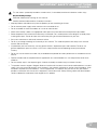
SpECIfICATIONS
61” (155cm)
19” (47cm)
40.5”
(103cm)
Before Assembly
Select the area where you are going to set up and operate your machine. For safe operation, the location must be on a
hard,levelsurface.Allowaworkoutareaofaminimum100”x58”(2.54mx1.47m).
Basic Assembly Tips
Follow these basic points when you assemble your machine:
1. Read and understand the “Important Safety Instructions” before assembly.
2. Collect all the pieces necessary for each assembly step.
3. Using the recommended wrenches, turn the bolts and nuts to the right (clockwise) to tighten, and the left (counter-
clockwise) to loosen, unless instructed otherwise.
4. When attaching 2 pieces, lightly lift and look through the bolt holes to help insert the bolt through the holes.
5. The assembly can require 2 people.
Maximum User Weight: 275 lbs. (125 kg)
Power Requirements:4DBatteries(LR20)–notincluded
OperationalVoltage:6VDC
Regulatory Approvals:
Optional AC Power Adapter: UL listed, CSA certified (or
equivalent),Rated120V60HzInput,9VDC,500mAOutput.
Class 2 or LPS.
!
This product, its packaging, and components contain
chemicals known to the State of California to cause
cancer, birth defects, or reproductive harm. This Notice
is provided in accordance with California’s Proposition
65. If you would like additional information, please refer
to our website at www.nautilus.com/prop65.

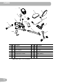
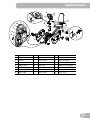
6
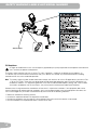
Item Qty Description Item Qty Description
1 1 Main Frame 8 1 Side Handlebars
2 1 Front Stabilizer 9 1 Console Mast
3 1 Rear Stabilizer 10 1 Console
4 1 Seat Rail 11 1 Left Pedal (L)
5 1 Seat Bracket Assembly 12 1 Right Pedal (R)
6 1 Seat Bottom 13 1 Water Bottle Holder
7 1 Seat Back
Note:MediaCableisintheConsolebox.
1
2
3
4
5
6
7
8
9
10
11
(L)
12 (R)
13
pARTS

7
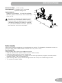
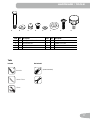
Tools
Included Not Included
6 mm/#2
Item Qty Description Item Qty Description
A 4 CarriageBoltM8x65 E 12 Flat Washer M8
B 5 Arc Washer M8 F 2 Rubber Limit Pad
C 4 Acorn Nut M8 G 8 PhillipsHeadScrewM6x35
D 12 HexScrewM8x15 H 1 AdjustmentKnob
A B C D E F G H
(recommended)
HARdWARE / TOOLS
13mm/17mm
15mm

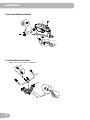
8
1. Attach Front Stabilizer to Main Unit
2. Install Handlebar to Seat Bracket
NOTICE: DonotcrimpcablefromHandlebar.
ASSEMBLY
A
X2
2
C
B
X2
1
5
8
A
C
E
X2
X2

9
3. Attach Seat Bottom and Seat Back to Seat Bracket
NOTICE: Donotcrimpcable.
6
7
G
X8
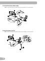
4. Slide Seat Assembly onto Seat Rail
NOTICE:Donotcrimpcables.
H
4

10
5. Install Seat Rail Assembly to Main Assembly
NOTICE:ConnectHeartRate(HR)cablesfromSeatRailandMainUnit.Donotcrimpcables.
6. Attach Rear Stabilizer to Seat Rail
NOTICE:ConnectHeartRate(HR)cablesfromSeatRailandHandlebar.Donotcrimpcables.
X4
E
D
6mm
3

11
7. Install Console Mast to Main Assembly
Note: You can attach a wire (or string) to the Console Cable and HR Cable to help pull the cables through the
Console Mast.
NOTICE:Donotcrimpcables.
X3
B
D
6mm
8. Install the Console to the Console Mast
Note: Hardware is pre-installed on Console and not on Hardware Card. Remove hardware from Console before you
connect the cables.
NOTICE: Donotcrimpcables.MakesurethattheswitchonthebackoftheConsoleisset to B (bike).
10
#2

12
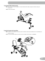
9. Install Pedals
Note: The Left Pedal is reverse-threaded. Be sure to attach Pedals on the proper side of the Bike. Orientation is
based from a seated position on the bike. The Left Pedal has an “L”, the Right Pedal an “R”.
10. Install Water Bottle Holder
Note: Hardware is pre-installed on Console Mast and not on Hardware Card.
12 (R)
11 (L)

13
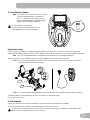
11. Install Batteries in Console
Note:TheconsoleusesDsizebatteries(LR20).Make
sure that the batteries point in the direction
of the +/– indicators in the battery bay. If you
use rechargeable batteries, the optional power
adapter will not recharge the batteries.
!
Donotmixoldandnewbatteries.
Donotmixalkaline,standard(carbon-zinc),or
rechargeable (Ni-Cd, Ni-MH, etc) batteries.
X4
+
–
Optional Power Adapter
The console for your machine can operate on battery power or AC power. For AC power, it is necessary to order the
optional Power Adapter. If batteries and the Power Adapter are installed, the console will use the Power Adapter to operate.
Note: If you use rechargeable batteries, the optional Power Adapter will not recharge the batteries.
After the machine is fully assembled, connect the Power Adaptor to the console and the wall outlet.
NOTICE: If you use a power adapter for your bike, make sure that the cord stays clear of the path of the pedals.
Attach the cord to the machine as shown:
NOTICE: It is recommended to remove batteries when they are not used, to avoid damage from battery corrosion.
To order the optional Power Adapter, go to: www.schwinnfitness.com/powersupply
Or call 1 (800) 605–3369.
12. Final Inspection
Inspect your machine to ensure that all hardware is tight and components are properly assembled.
Be sure to record the serial number in the field provided at the front of this manual.
!
Donotuseorputthemachineintoserviceuntilthemachinehasbeenfullyassembledandinspectedforcorrect
performance in accordance with the Owner’s Manual.

14
Leveling Your Bike
The levelers are the polygonal end caps on the Rear Stabilizer. Turn the end cap to adjust the level.
Makesurethebikeislevelandstablebeforeyouexercise.
Moving Your Bike
To move the recumbent bike, carefully lift the rear end of the bike and slowly push the bike to the desired location.
NOTICE: Be careful when you move the bike. Abrupt motions can affect the computer operation.
BEfORE YOU START

15
!
This icon means a potentially hazardous situation which, if not avoided, could result in death or serious injury.
Before using this equipment, obey the following warnings:
!
ReadandunderstandthecompleteManual.KeeptheManualforfuturereference.
Read and understand all warnings on this machine. If at any time the Warning stickers become loose, unreadable
or dislodged, contact Nautilus
®
Customer Service for replacement stickers.
• Childrenmustnotbeletonorneartothismachine.Movingpartsandotherfeaturesofthemachinecanbe
dangerous to children.
• Notintendedforusebyanyoneunder14yearsofage.
• Consultaphysicianbeforeyoustartanexerciseprogram.Stopexercisingifyoufeelpainortightnessinyour
chest, become short of breath, or feel faint. Contact your doctor before you use the machine again. Use the values
calculated or measured by the machine’s computer for reference purposes only.
• Beforeeachuse,examinethismachineforloosepartsorsignsofwear.Donotuseiffoundinthiscondition.Monitor
the Seat, Pedals, and Crank Arms closely. Contact Nautilus
®
Customer Service for repair information.
• Maximumuserweightlimit:275lbs.(125kg).Donotuseifyouareoverthisweight.
• Thismachineisforhomeuseonly.
• Donotwearlooseclothingorjewelry.Thismachinecontainsmovingparts.Donotputngersorotherobjectsinto
movingpartsoftheexerciseequipment.
• Setupandoperatethismachineonasolid,level,horizontalsurface.
• MakethePedalsstablebeforeyousteponthem.Usecautionwhenyousteponandoffthemachine.
• Disconnectallpowerbeforeservicingthismachine.
• Donotoperatethismachineoutdoorsorinmoistorwetlocations.Keepthefootpedalscleananddry.
• Keepatleast24”(0.6m)oneachsideofthemachineclear.Thisistherecommendedsafedistanceforaccessand
passagearoundandemergencydismountsfromthemachine.Keepthirdpartiesoutofthisspacewhenmachineis
in use.
• Donotoverexertyourselfduringexercise.Operatethemachineinthemannerdescribedinthismanual.
• CorrectlyadjustandsafelyengageallPositionalAdjustmentDevices.MakesurethattheAdjustmentDevicesdonot
hit the user.
• Exerciseonthismachinerequirescoordinationandbalance.Besuretoanticipatethatchangesinspeedand
resistance level can occur during workouts, and be attentive in order to avoid loss of balance and possible injury.
IMpORTANT SAfETY INSTRUCTIONS

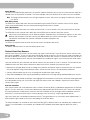
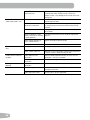
16
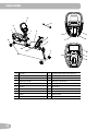
A Console K Contact Heart Rate (CHR) Sensors
B Side Handlebars L Power Connector
C Adjustable Seat M Battery Bay
D AdjustmentKnob N Machine Type Switch
E Fully Shrouded Flywheel O Media Tray
F Levelers P MP3 Input
G Stabilizers Q Speakers
H Transport Rollers R Headphones Output
I Pedals S Media Cable
J Water Bottle Holder
fEATURES
A
B
D
E
F
G
H
I
B
J
K
C
S
Q
L
M
O
P
Q
N
R

17
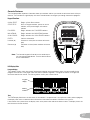
Console Features
The Console provides important information about your workout and lets you control the resistance levels while you
exercise.TheConsolehasagriddisplaywithtouchcontrolbuttonstonavigateyouthroughtheexerciseprograms.
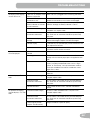
Keypad Functions
QUICKSTART BeginsaQuickStartworkout
START/STOP Starts a Program workout, pauses an active
workout, and if pushed again, will end the
workout
FUNRIDES BeginsselectionofaFUNRIDESworkout
MOUNTAINS Begins selection of a MOUNTAINS workout
CHALLENGES BeginsselectionofaCHALLENGESworkout
ENTER Confirms information
Increase () Increases a value (time or workout resistance
level)
Decrease() Decreasesavalue(timeorworkoutresistance
level)
Note: The Console keypad will not adjust the sound output
for a connected media device. Use the volume control
on the media device.
LCD Display Data
Program Display
TheProgramDisplayshowsthenameoftheprogramselectionandthegridareashowsthecourseproleforthe
program. Each column in the profile shows one interval (workout segment). The higher the column, the higher the
resistance level for that interval. The flashing column shows your current interval.
Time
The TIME display field shows the time count in the workout. If no preset time is set up for the current workout program,
thedisplayvaluestartsatzeroandcountsforwarduntiltheendoftheworkout.Maximumtimeis99:59.
If the workout has a preset time, the display starts at the preset value and counts down to zero. The display shows the
total time count for the workout.
Battery
indicator
Program
display

18
Speed / Distance
TheSPEED/DISTANCEdisplayeldshowsthemachinespeedinkilometersperhour(km/h)ormilesperhour(mph)for6
seconds,thentheDistancefor6seconds.TheDistancedisplayshowsthedistancecount(milesorkm)intheworkout.
Note: To change the measurement units to English Imperial or metric, refer to the “Changing Unit Measures” section in
this manual.
RPM / KCAL (Calories)
TheRPM/KCALdisplayeldshowsthemachinerevolutionsperminute(RPM)for6seconds,thentheKCALdisplay
showstheestimatedcaloriesthatyouhaveburnedduringtheexercisefor6seconds.
Level / HR (Heart Rate)
TheLEVEL/HRdisplayeldshowsthecurrentresistancelevel(1–8)for6seconds,thenyourHeartRatefor6seconds.
The HR display shows the heart rate in beats per minute (BPM) from the Contact Heart Rate sensors.
!
Consultaphysicianbeforeyoustartanexerciseprogram.Stopexercisingifyoufeelpainortightnessinyourchest,
become short of breath, or feel faint. Contact your doctor before you use the machine again. Use the values
calculated or measured by the machine’s computer for reference purposes only.
Results Indicator
The RESULTS indicator comes on when the Console shows the workout data results.
Battery Indicator
The Battery Indicator comes on when the battery power is low.
Contact Heart Rate Sensors
Contact Heart Rate (CHR) sensors send your heart rate signals to the Console. The CHR sensors are the stainless steel
parts of the Handlebars. To use, put your hands comfortably around the sensors. Be sure that your hands touch both the
top and the bottom of the sensors. Hold firm, but not too tight or loose. Both hands must make contact with the sensors
for the Console to detect a pulse. After the Console detects four stable pulse signals, your initial pulse rate will be shown.
Once the Console has your initial heart rate, do not move or shift your hands for 10 to 15 seconds. The Console will now
validate the heart rate. Many factors influence the ability of the sensors to detect your heart rate signal:
• Movement of the upper body muscles (including arms) produces an electrical signal (muscle artifact) that can interfere
with pulse detection. Slight hand movement while in contact with the sensors can also produce interference.
• Calluses and hand lotion may act as an insulating layer to reduce the signal strength.
• SomeElectrocardiogram(EKG)signalsgeneratedbyindividualsarenotstrongenoughtobedetectedbythesensors.
CHRdetectionmaybelimitedtowalkingorslowjoggingduetotheextrememuscleartifactsandhandmotiongenerated
by a comfortable running style. If your heart rate signal ever seems erratic after validation, wipe off your hands and the
sensors and try again.
Heart Rate Calculations
Yourmaximumheartrateusuallydecreasesfrom220BeatsPerMinute(BPM)inchildhoodtoapproximately160BPMby
age60.Thisfallinheartrateisusuallylinear,decreasingbyapproximatelyoneBPMforeachyear.Thereisnoindication
thattraininginuencesthedecreaseinmaximumheartrate.Individualsofthesameagecouldhavedifferentmaximum
heart rates. It is more accurate to find this value by getting a stress test than by using an age related formula.
Yourat-restheartrateisinuencedbyendurancetraining.Thetypicaladulthasanatrestheartrateofapproximately72
BPM, whereas highly trained runners may have readings of 40 BPM or lower.
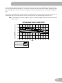
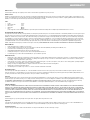
The Heart Rate table is an estimate of what Heart Rate Zone (HRZ) is effective to burn fat and better your cardiovascular
system. Physical conditions vary, therefore, your individual HRZ could be several beats higher or lower than what is
shown.

19
Themostefcientproceduretoburnfatduringexerciseistostartataslowpaceandgraduallyincreaseyourintensity
untilyourheartratereachesbetween60–85%ofyourmaximumheartrate.Continueatthatpace,keepingyourheart
rate in that target zone for over 20 minutes. The longer you maintain your target heart rate, the more fat your body will
burn.
The graph is a brief guideline, describing the generally suggested target heart rates based on age. As noted above, your
optimal target rate may be higher or lower. Consult your physician for your individual target heart rate zone.
Note:Aswithallexercisesandfitnessregimens,alwaysuseyourbestjudgmentwhenyouincreaseyourexercise
time or intensity.
20-24
FAT-BURNING TARGET HEART RATE
Heart Rate BPM
(beats per minute)
Age
25-29
0
50
100
150
200
250
30-34 35-39 40-44 45-49 50-54 55-59 60-64 65-69 70+
196
191
186
181
176
171
166
161
156
151
146
167
162
158
154
150
145
141
137
133
128
126
Maximum Heart Rate
Target Heart Rate Zone
(keep within this range
for optimum fat-burning)
118
115
112
109
106
103
100
97
94
91
88

20
OpERATIONS
What to Wear
Wearrubber-soledathleticshoes.Youwillneedtheappropriateclothesforexercisethatallowyoutomovefreely.
How Often Should You Exercise
Consultaphysicianbeforeyoustartanexerciseprogram.Stopexercisingifyoufeelpainortightnessinyourchest,
become short of breath, or feel faint. Contact your doctor before you use the machine again. Use the values
calculated or measured by the machine’s computer for reference purposes only.
• 3 times a week for 30 minutes each day.
• Schedule workouts in advance and try to follow the schedule.
Seat Adjustment
Correctseatplacementencouragesexerciseefciencyandcomfort,whilereducingtheriskof
injury.
1. With a Pedal in the forward position, place the ball of your foot over the center of it. Your leg
should be bent slightly at the knee.
2. If your leg is too straight or your foot cannot touch the Pedal, move the seat forward. If your
leg is bent too much, move the seat toward the back.
Step off the bike before you adjust the seat.
3. Loosen and pull the adjustment knob on the seat tube. Adjust the seat to the desired
position.
4. Release the adjustment knob to engage the locking pin. Be sure that the pin is fully engaged
and fully tighten the knob.
Foot Position / Pedal Strap Adjustment
Footpedalswithstrapsprovidesecurefootingtotheexercisebike.
1. Put the ball of each foot on the Pedals.
2. Rotate the Pedals until one can be reached.
3. Fasten the strap over the shoe.
4. Repeat for the other foot.
BesuretoesandkneespointdirectlyforwardtoensuremaximumPedalefciency.Pedalstrapscan
be left in position for subsequent workouts.
Power-Up / Idle Mode
TheConsoleoperateson(4)Dsizedbatteries.Onceinstalled,theConsolewillenterPOWER-UPmodeifanybuttonis
pushed, or if it receives an indication from the RPM sensor as a result of pedaling the machine.
Note: An optional power adapter is available from www.schwinnfitness.com/powersupply or call 1(800) 605–3369.
Auto Shut-Off (Sleep Mode)
IftheConsoledoesnotreceiveanyinputorthereisnopedalmovementinapproximately5minutes,itwillautomatically
shutoff.TheLCDdisplayisoffwhileinSleepMode.
Note: The Console does not have an On/Off switch.
Quick Start / Manual Program
The Quick Start / Manual program lets you start a workout without entering any information.
1. Sit on the seat.
2. PushtheQUICKSTARTbuttonandstarttopedal.
3. Tochangetheresistancelevel,pushtheIncrease/Decreasebuttons.ThedefaultQuickStartresistancelevelis1.The
time will count up from 00:00.
Page is loading ...
Page is loading ...
Page is loading ...
Page is loading ...
Page is loading ...
Page is loading ...
Page is loading ...
Page is loading ...
-
 1
1
-
 2
2
-
 3
3
-
 4
4
-
 5
5
-
 6
6
-
 7
7
-
 8
8
-
 9
9
-
 10
10
-
 11
11
-
 12
12
-
 13
13
-
 14
14
-
 15
15
-
 16
16
-
 17
17
-
 18
18
-
 19
19
-
 20
20
-
 21
21
-
 22
22
-
 23
23
-
 24
24
-
 25
25
-
 26
26
-
 27
27
-
 28
28


Ask a question and I''ll find the answer in the document
Finding information in a document is now easier with AI
Related papers
-
Schwinn A15 Owner's manual
-
-
Schwinn A15 Owner's manual
-
-
Schwinn AD2 Assembly & Owner's Manual
-
-
-
-
-
Other documents
-
Nautilus R514C Assembly & Owner's Manual
-
 Universal R-20 Assembly Manual / Owner's Manual
-
 Universal Fitness 100477 Owner's manual
-
-
Bowflex BowFlex Max Trainer M5 Owner's manual
-
-
-
-
-

