
9OOMHz
CORDLESS TELEPHONE
VTECH COMMUNICATIONS LTD.
IVrECH]
Is a trademark of VTECH COMMUNICATIONS LTD..,
a
member
of THE.VTECH GROUP OF COMPANIES.
I
Distributed in the U.S.A. by VTECH Communications, 8770 SW Nimbus Avenue
I
Beaverton, Oregon, 97008.
Distributed in Canada by VTECH Electronics Canada Ltd., Suite 200
-
7671 Alderbridge
Way Richmond, B.C.
V~X
1Z9.
Copyright 1997 for VTECH COMMUNICATIONS LTD..
Printed in China
BEFORE USING YOUR NEW
PHONE, WE STRONGLY
RECOMMEND
YOU
READ THIS

@j
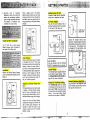
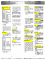
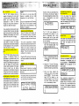
OPTIONAL HEADSET INSTALLATION
AND OPERATING INSTRUCTIONS
OPERATION
NOTE:
Whenever a compatible
Headset is connected to the cordless
Handset, the
micropho'ne on the
Handset will be
MUTED.
This is
done to limit the effect of background
noise.
The following operational
characteristics apply to VTech
Headsets. The same may also apply
to other
(non-VTech) compatible
headsets, but VTech assumes no
responsibility for their performance.
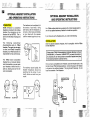
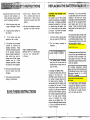
The VTech brand compatible
Headset has a monaural design
which is reversible, so you can wear
your Headset on either the left or
right ear, leaving one ear free for
room conversation.
ON
RIGHT
EAR
ON
LEFT
EAR
!
The headband can be adjusted to fit
the contour of your head. Using
both hands, slide the headband up
or down so that it rests comfortably
on your head with the speaker
cushion centered against your ear.
For maximum sound quality, the
flexible microphone should be
positioned at the corner of your
mouth, about one inch from your
mouth.
.........
........
.....
OPTIONAL HEADSET INSTALLATION
.....
9::.
"...
:
.......
..........
..........
.......
.....
.....
AND OPERATING INSTRUCTIONS
I.'...'.
.......
.........
..........
.........
..........
,
........
4:.
.........
.:.:
i:':.,.
:.:.:.:"
:
.........
........
.........
......
........
.........
,.,.
..........
.......
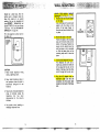
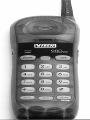
Your VTech cordless telephone is equipped with a 2.5mm Headset Jack for
........
....
.....
........
,
...
...
use with an
optional
accessory Headset for hands-free operation
...
,
,..
,
.....:...
1::
:_._...
.::.
...
ij..::.
....
,::_
:
,...
.
,
..
....
If
you choose to use the Headset option, you must do the following:
...
....
.....
.
t.
.::.
_
.
?.
......
.?.'.'..
L"
'_'._'
.....
...
....
.....
....
INSTALLATION
.......
.......
.....
.......
/:..
..
.....
Obtain an optional accessory Headset, which is compatible with the VTech
.......
........
.......
........
.........
........
cordless telephone
.......
.......
,
.
,
......
.......
......
......
.......
......
......
.....
.....
~lease'contact VTech Comrnunicatlons Customer Service, toll-fiee at
1-800-595-9511, in Canada at 1-800-267-7377, for dealer information in
$our local area.You can also purchase a compatible Headset directly from
VTech Communications Customer Service.
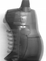
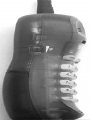
force the connection. See illustration
J
Once you have a compatible 2.5mm Headset, locate the Headset Jack on the,
Handset of your VTech cordless telephone. Connect the plug on the Headset
to the jack on'the cordless .Handset. The plug should fit securely. Do not
PLUGTHE
OPTIONAL
HEADSET
INTO
THE

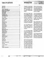
TABLE OF CONTENTS
...
Page
INTRODUCTION
......................................................................................................
1
...
Special Features
.............................................................................................................
2
...............................................................................................................
..-i.
Parts Check List 3
.......................................
....................................
FCC AND IC REGULATIONS
.........
4
.......................................................................
.
IMPORTANT SAFETY INSTRUCTIONS
7
!'
...
I;
REPLACING THE BAlTERY PACK
..............................................................................
9
GETTING STARTED
.....................................................................................................
13
..........................................................................................................
"
WALL MOUNTING 15
.................................
....................................................................
THE LCD DISPLAY
..
16
':
;
'"THE HANDSET LAYOUT
.................................................................................................
-17
THE BASE UNIT LAYOUT
............................................................................................
-18
QUICK REFERENCE GUIDE
...................
...
...............................................................
19
BASIC OPERATION
.................................................................................................
21
............................................................................................
ADVANCED FUNCTIONS
22
CID Withcall Waiting
.......................................................................................................
22
Switching Calls
..............................................................................................................
22
Temporary Tone
....................................
....
.......................................................................
22
Prograinming The Ringer
................................................................................................
22
Changing Ringer Types
.....................................................................................................
22
CALL WAITING
.........................................................................................................
,.22
TEMPORARY TONE
......................................................................................................
22
Turning
Off
The Ringer
..........................
..
...................................................................
23
Checking The Ringer Type
..........................
..
................................................................
23
CLWDEL Key Function
..........................
....
.................................................................
23
Advanced Dialing
.............................................................................................................
24
MEMORY DIALING
.......................................................................................................
25
....................................................................
Storing Speed Dial Numbers
.....................
..
25
Dialing From Memory
.....................................................................................................
26
Changing Stored Numbers
....................
..
.......................................................................
26
Deleting Stored Numbers
..................................................................................................
26
Storing Special Codes
......................................................................................................
27
...............................................................................................................
CID-CALLER ID
28
CID-CALLER ID
........................
..
................................................................................
..28
Receiving and Storing Calls
..............................................................................................
28
Dialing From CID Memory
...............................................................................................
28
Out Of Area Calls
...........................................................................................................
29
"Privateu Calls
...............................................................................................................
29
Transmission Error
....................
....................
...................................................................
29
Reviewing Numbers
.......................................................................................................
30
Deleting Numbers
..........................................................................................................
31
ADDITIONAL OPERATING TIPS
................................................................................
32
.........................................................................................
MAINTENACE
....................
..
.33
....................................................................
IN
CASE OF DIFFICULTY
.......................
..
35
WARRANTY
....................................................................................................................
36
TECHNICAL SPECIFICATIONS
......................................................................................
37
Congratulations! You have purchased
one of the most sophisticated cordless
telephones on the market! The
VT
1921 has been designed to offer a
new standard in cordless telephone
technology.
Unlike most other cordless phones,
the VT 1921 digitizes your voice using
advanced ADPCM digital voice coding
to provide noise and distortion free
performance. In most conditions you
will not be able to
te!l you are using
a cordless phone. Gone are the
annoyances of static, interference
and having to listen to other people's
conversations on your cordless phone.
The VT 1921 scrambles your voice
before it transmits it. This allows you
the security of knowing that no one
can tune in and eavesdrop on your
conversations.
The VT 1921 decodes and displays
name
and/or number Caller ID (CID)
information where available and when
subscribed to. The alpha-numeric
display can show both
thename and
number of the calling party. Up to 24
name characters or 11 phone number
digits can be displayed on the LCD.
With the VT 1921, the user can easily
answer a call by pressing any key
otherthan the OFF, MUTEorVOLUME
Keys. In addition, the handset keypad
and LCD illuminate while the handset
rings to signal an incoming call. This
is very useful in a dark environment.
The VT 1921 also provides a one-
way
PageIFind. Pressing the base
PAGE key will cause the .handset to
ring in a manner which distinguishes
it from normal incoming ringing. This
can be used to alert the handset user,
or to simply locate the handset in the
event that it is misplaced.
The VT 1921 uses special memory in
both the base and handset which is
not susceptible -to power failures.
This provides permanent storage of
a11 memory dial numbers, CID
information as well as the base and
handset security, codes.
When an optional battery pack is
installed, in the base unit, the
VT
1921
uses this battery pack to provide
operational backup in case of power
failure. In this way you have access
to all normal phone functions during a
total power outage. Calls can still be
placed and received without
interruption. More than
5
hours backup
will be possible with a fully charged
battery pack in the base unit.
The
VT
1921 informs you that another
extension is currently in use on the
same phone line. The
phone.will also
alert you when you are Out of Range,
even when you're not using the phone!

Fully Digital Link between Hand-
set and Base with ADPCM voice
.
,:.coding.
Digitally-Scrambled Voice Com-
munication.
Name
/
Number CID display.
2 row by 12 character 5x7 dot
matrix alpha-numeric LCD.
50 CID memory locations.
Backlit LCD on the handset.
Backlit handset keypad.
20 location Programmable Memory
for
20
Digit Phone Number.
10
Channel Operation with auto
channel selection.
Out-of-Range indication while the
handset is in use or in standby
mode.
Removable handset battery pack.
Spare battery charger in the base
unit.
Complete battery back-up in case of
power failure (with optional spare
battery pack installed in base).
Face-up Handset charging.
Easy answer
-
When the phone
rings, simply press any key other
than OFF, MUTE, or the Volume
Keys on the handset to answer.
Auto hang up when returning the
handset to the base' cradle.
Extension in use indicator.
24 Bit Digital Security Code.
DTMF and Pulse Dialing.
Low Battery Detect and Warning
indicator.
Up to
7
hours continuous talk
time or
7
days standby time.
Volume Adjust on Handset.
REDIAL, HOLD, PAGE and MUTE.
Hearing-Aid Compatible Receiver.
Detachable power supply.
Non-volatile storage of security
code and memory dial records.
Programmable Ringer Types.
This manual is designed to make you
familiar with the VT
1921.
We strongly
recommend you read the manual
before using your phone.
parts
~i~~
,
i:;:,:'.:.i
,
.
;?:@
.
.
&~i:~j$+$
,
.
.
,
.
To purchase replacement battery
.
I.._.
..r_:...
_..__.UI..
dl
1.
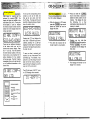
Base unit, Handset and
AC
ada6or
packs, call VTECH Communications
2. One-Line Telephone Cord
at 1-800-595-951
1
in the
U.S.
and
3.
Battery Pack 1-800-267-7377 in Canada.
4.
Wall mount accessory
5.
Belt clip
HANDSET BASE UNIT
WALL MOUNTING
BRACKET
BATTERY PACK
,
AC POWER ADAPTOR
TELEPHONE LINE CORD
BELT-CLIP
SPECIAL FEATURES
Parts Check List

This equipment complies with Parts
15 and 68 of the Federal Communi-
cations Commission (FCC) rules for
the United States. It also complies
with regulations
RSS210 and CS-03
of lndustry and Science Canada.
Operation is subject to the following
two conditions: (1) this device may not
cause interference, and (2) this device
must accept any interference, including
interference that may cause undesired
operation of the device.
A
label is located on the underside of
the base unit containing either the
FCC registration number and Ringer
Equivalence Number (REN) or the 1C
registration number and Load Num-
ber. You must, upon request, provide
this information to your local telephone
company.
This equipment is compatible with
inductively coupled hearing aids.
should you experiencetrouble with this
telephone equipment, please contact:
VTECH COMMUNICATIONS
SERVICE DEPT. at 1-800-595-951
1
in the U.S. and 1-800-267-7377
in Canada.
For
repaidwarranty information. The
telephone company may ask you to
disconnect this equipment from the
line network until the problem has
been corrected.
FCC
Part
15
Warning: Changes or modifications
to this unit not expressly approved by
the party responsible for compliances
could void the user's authority to
operate the
equipment.,
The equipment has been tested and
found to comply with part
15
of the
FCC rules. These limits are designed
to provide reasonable protection
against harmful interference in a
residential installation. This equipment
generates, uses and can radiate radio
frequency energy and, if not installed
and used in accordance with the
instructions, may cause harmful
interference to radio communications.
However, there is no guarantee that
interference will not occur in a particular
installation. If this equipment does
cause harmful interference to radio or
television reception, which can be
determined by turning the equipment
off and on, the user is encouraged to
try and correct the interference by one
or more of the following measures:
-
Reorient or relocate the receiving
antenna.
-
Increase the separation between
the equipment and receiver.
-
Connect the equipment into an
outlet or on a circuit different from
that to which the receiver is
connected.
-
Consult the dealer or an experienced
radiom technician for help.
FCC
Part
68
.
The FCC requires that you connect your
cordless telephone to the nationwide
telephone network through a modular
telephone jack: (USOC
RJ11 C,
RJ11W or RJ14),.
Your telephone company may
discontinue your service if your
equipment causes harm to the telephone
network. They will notify you in advance
of disconnection, .if possible. During
notification, you will be informed of your
right to file a complaint with the FCC.
Occasionally, yourtelephone company
may make changes in its facilities,
equipment, operation, or procedures
that could affect the
operation.of your
equipment. If so, you will be given
advance notice of the change to give
you an opportunity to maintain
uninterrupted sewice.
The base unit contains no user
serviceable parts. The handset contains
a user replaceable battery pack.
If
it is determined Ithat your telephone
equipment is malfunctioning, the FCC
requires that it ndt be used and that
it be unplugged from the modular jack
until the problem has been corrected.
Repairs to this telephone equipment
can only be made by the manufacturer
or its authorized agents or by others
who may be authorized by the FCC.
For repair procedures, follow the
instructions outlined under the VTECH
Limited
Warranty1
This equipment.may not be used on
coin service provided by the phone
company or Party Lines.
The REN is useful in determining the
number of devices you may connect
to your telephone line and still enable
the devices to ring when you receive
a call. The general rule is that the REN
value should not exceed 5.OA total;
however, contact your local telephone
company for the specific number in
your area.
IC (Industry Canada)
This telephone is registered for use in
Canada.
Notice:The REN assigned to this
device denotes the number of
devices you may connect to
the telephone loop which is
used by the device to prevent
overloading The termination
on a loop may consist of any
combination of devices
subjected only to the
requirement that the sum of
the REN does not exceed five
(5.0)
Notice:The Industry Canada label
identifies certified equipment.
This certification means that
the equipment meets certain
telecommunications network
protective, operational and
safety requirements. The
Department does not
guarantee the equipment will
operate to the user's
satisfaction.

Before installing this equipment, users
should ensure that it is permissible to
be connected to the facilities of the
local telecommunications company.
The equipment must also be installed
using an acceptable method of
connection. The customer should be
aware that compliance with the above
conditions may not prevent degradation
of services in some situations.
Repairs to certified equipment should
be made by an authorized Canadian
maintenance facility designated by the
supplier. Any repairs or alterations
made by the user to this equipment,
or equipment malfunctions, may give
the telecommunications company
cause to request the user to disconnect
the equipment.
Users should ensure for their own
protection that the electrical ground
connections of the power utility,
telephone lines and internal metallic
water pipe system, if present, are
connected together. This precaution
may be particularly important in rural
areas.
Caution: Users should not attempt to
make such connections
themselves, butshould contact
the appropriate electrical
inspection authority, or
electrician, as appropriate.
Your
VT
1921
is designed to operate
at the maximum power allowed by the
FCC and
IC. This means your
handset and base unit can
communicate only over a certain
distance
-
which will depend on the
location of the base unit and handset,
weather, and the construction and
layout of your home or office.
When using yourtelephone equipment,
basic safety precautions should always
be followed to reduce the risk of fire,
electric shock
an/3 ,injury to persons,
including the following:
!
1.
Read and
'
understand all
instructions.
2.
Follow all warnings and instructions
marked on the product.
3.
Unplug this product from the wall
outlet before oleaning. Do not use
liquid cleaners or aerosol cleaners.
Use a damp Cloth for cleaning.
4.
Do not use thik product near water
(for example,! near a bath tub,
kitchen sink, or swimming pool).
7.
This product should be operated
only from the type of power source
indicated on the marking label. If
you are not sure of the type of
power supply to your home, consult
your dealer or local power
company.
8. Do not allow anything to rest on
the power cord. Do not locate this
product where the cord will
be
abused by persons walking on it.
9.
Never push objects of any kind
into this product through cabinet
slots as they may touch dangerous
voltage points or short out parts
that could result in a risk of fire or
electric shock. Never spill liquid of
any kind on the product.
5.
Do not place this product on an
10.To reduce the risk of electric shock,
unstable
cart,!stand, or table. The
do
not
disassemble this product, but
product may 'fall, causing serious
take it to a
VTECH
authorized service
damage to the product.
facility. Opening or removing cabinet
I
parts other than specified access
6.
Slots and opgnings in the cabinet
doors may expose you to dangerous
and the back rJr bottom are provided voltages or other risks. Incorrect
for ventilation1 To protect it from
reassembling can cause electric
overheating, hese openings must
i
shock when the appliance is
not be bloc ed by placing the subsequently used.
product on t e bed, sofa, rug, or
other similar urface. This product
11
.Do not overload wall outlets and
should never be placed near or
extension cords as this can result
over a radia,or or heat register.
in the risk of fire or electric shock.
This product should not be placed
in a built-in insjtallation where proper
ventilation is not provided.

i....
..........
---
.
.
-L-.;;_..;..
-r.*.,,
Y,;
INSTRUCTIONS
I
........
i
.......................
,
.
I
12.Unplug this product from the wall 13.Avoid using a telephone (other
outlet and refer servicing to a than a cordless type) during an
VTech authorized service facility electrical storm. There may be a
under the following conditions: remote risk of electric shock from
lighting.
A.
When the power supply cord
or plug is damaged or frayed.
14.Do not use the telephone to report a
gas leak in the vicinity of the leak.
B. If liquid has been spilled into
the product.
C. If the product has been
exposed to rain or water.
D.
If
the product does not operate
normally by following the
operating instructions. Adjust
onlythosecontrolsthatarecovered
VTECH COMMUNICATIONS
by the operating instructions, SERVICE DEPT. at 1-800-595-951 1
because improper adjustment of in the
US. and 1-800-267-7377
other controls may result in In Canada.
damage and will often require
extensive work by a VTech
authorized technician to restore
the product to normal operation.
E. If the product has been dropped
and the cabinet has been
..
damaged.
F.
If the product exhibits a distinct
change in performance.
SAVE THESE INSTRUCTIONS
CHARGING THE ,HANDSET ,BAT-
TERY PACK
The handset of your
VT
1921 cordless
telephone is powered by a rechargeable
battery pack. It charges automatically
whenever the handset is in the base.
You should charge the battery pack
for 16 hours when you first receive
your phone.
Yo)JIII know the battery
pack needs charging when:
The phone epits a warning tone
when you press the PHONE key.
The low battery message is
displayed:
I
!
The handsel seems completd
dead, the LCD is clear and the
handset does not beep when you
press the keys.
To Charge The. Battery Pack
To charge the battery pack, place the
handset in the, base unit. The
CHARGE indicator will light to show
the handset is seated properly and
the battery is charging. It is
recommended
t at the battery pack
be charged for at least 16 hours
T
initially and
8
h urs for maintenance
charging. You c
3
n use your telephone
before that with diminished capacity,
but it is best to c arge the battery pack
fully. It will ta e several recharge
cycles to ma imize the charge
capacity of you battery pack. The
maximum batte life between charges
is 7 hours of co tinuous talk time or
7
days of stand by.
i
Alternatively,
if
you have purchased
a spare battery pack and it has been
charging in the base unit, simply
exchange the drained handset battery
pack with the fully charged replace-
ment battery pack from the base
charger. Place the drained handset
battery pack into the base charger to
recharge.
The base spare battery charger does
NOT charge a battery pack as quickly
as the handset battery charger. A full
charge requires 24 hours when using
the spare battery charger.
The battery pack can be recharged many
times, but if you get a low-battery signal
even after 16 hours of charging in the
base cradle (or 24 hours in the base
spare battery charger), the battery
pack(s)
should be replaced.
To purchase replacement battery
packs, call VTech Communications at
1-800-595-951 1 in the U.S. and VTech
Electronics Canada Ltd at 1-800-
Your Nicad battery pack recharges
whenever the Handset is returned to
the Base Unit cradle. You may return
the Handset to its cradle whenever
you're not using the phone.
IT'S IMPOSSIBLE TO OVER CHARGE
THE BATTERY PACK
A WORD ABOUT RECHARGEABLE
BATTERIES

Follow the steps below:
1.
Remove the battery case cover
by pressing on the ridged lines
and sliding downward.
PRESS
and
SLIDE
DOWNWARD
2.
Discard the old battery pack. Don't
put the old battery pack in a trash
compactor or a fire
-
it could burst.
3.
Place the new battery pack in its
housing with the metal contacts
facing
-down.
PLACE
THE
NEW
BATTERY PACK
INTO THE
BAl-rER
COMPARTMENT
PLEASE NOTE THE
CORRECT POSITIOh
OF THE BATTERY
PACK WHEN
CHANGING BATTER'
4.
Replace the battery case cover
by sliding the cover upwards.
SLIDE IN THE
5.
If the new battery pack is not
already charged, place the hand-
set in the cradle of the base unit
to allow it to charge for
16
hours.
EAUTIO~~$&,$
4
::i
'
~ot~~duce the Risk of
ire
or lnju6
to parsons, read and Follow the
Instru~tions~yyY~*-~
*
.-
%
1.
Use only VTECH rechargeable
battery pack.
2.
Do not dispose of the battery in a
fire. The cell may explode.
IMPORTANT: Do not dispose of this
battery into household garbage. For
information on recycling or proper
disposal, consult your local solid waste
collection or disposal organization.
3.
Do not open or mutilate the
battery. Released electrolyte is
corrosive and may cause damage
to the eyes or skin. It mav be
toxic if swallowed.
4.
Do not dispose of the battery in a
fire. The cell may explode.
(contained in ciur product) indicates
that VTech Col"nmunications,lNC. is
voluntarily p'articipating in an
industry program to collect and
recycle these batteries at the end of
their useful lives,when taken out of
service within the United States and
Canada.
The RBRCa program provides a
convenient alternative to placing
used nickel-cadmium batteries into
the trash or municipal waste,which
be illegal in your areas.
VTech's payments to RBRCmmake
it easy for you to drop off the spent
battery at local retailers participating
in the
RBRC" program or at
authorized VTech product service
centers. Please call
1-800-8-BATTERYTM for information
on Ni-Cd battery recycleing and
disposal banslrestrictios in your
area.VTechls involvement in this
program is part of its commitment to
protecting our environment and
conserving natural resources.
Remove the nickel-cadmium
battery pack by pressing on the lock
knob and sliding downward as
mentioned on this page.
RBRCBis
a
registered trademark
of
Rechargeable Battery
Recycling Corporation.
The RBRC Seal

5.
Exercise care in handling
batteries in order not to short the
battery with conducting materials
.
;
such as rings, bracelets, and keys.
The battery. or conductor may
overheat and cause burns.
Place a battery pack in the Spare
Battery charger. Make sure the metal
charging contacts on the underside of
the battery pack are aligned with the
charging contacts in the Spare Battery
charger.
SPARE BATTERY CHARGER
The VT 1921 has a built-in spare
Battery Charger, which is located in
the cradle of the Base Unit.
Installation
Remove the Spare Battery charger
cover by pressing the release tab and
lifting up.
Power
Backu~
When a Spare ~attery pack is installed
in the Base Unit, the VT 1921 uses
this battery pack to provide operational
backup in case of a power failure. If
you have a fully charged battery pack
in the Spare Battery pack charger and
there is a power outage, you will still
be able to place and receive calls for
up to five
hours.However, Caller ID
may not function properly.
Replacing a Drained Handset bat-
tery
The Spare battery pack can also be used
to replace a drained Handset battery
pack to ensure uninterrupted use. Be
sure to put the drained battery pack in
the Spare Battery charger for recharging.
Setting
UpcYour
VT
1921
-
d
"
.-
--
Choose an area near an electrical
-
outlet and a telephone wall jack.
AC Power Adaptor
Plug the
AC
power adaptor into an
electrical outlet and the DC connector
to the back of the base unit.
TELEPHONE
A
CAUTION:
Use only CLASS 2 9V DC
POWER
SUPPLY included with your phone.
Handset Ringer
,
:
:
-
The handset ringer is programmed
ON
as the factory default setting. Refer
to PROGRAMMING THE RINGER on
page
23
for more information.
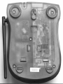
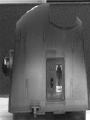
Setting the Tonelpulse Switch
.
The TONEIPULSE switch is located
on the bottom of the base unit and is
factory set to TONE. If you have touch
tone service, do not change the switch
setting. If you have rotary (Pulse)
service, set the switch to PULSE.
Please note that the Spare Battery
compartment charges at a slower rate
than a battery pack charging in the
Handset. It takes
24
hours to fully
charge a battery pack in the Spare
Battery charger.
TONE PULSE
SELECTION
Charge the handset battery pack
before use. The battery pack recharges
automatically whenever the handset is
in the base unit. The batteries must
be charged for
16
hours before using
your phone for the first time.
ConnecL
T~!_ep~.s!?~J&g&C,~$&
&:
plug one end of the telephone cord
into a wall jack and the other end into
the back of the Base Unit.

Check for a dial tone. After the
battery pack is charged, rotate the
Base Unit antenna to an upright
position. Pick up the Handset and
presscPHONE) "PHONE ON" will
appear on the
LCD,
and you will hear
a dial tone. If not, see 'IN CASE OF
DIFFICULTY' on page
34.
Fill in the telephone number card on
the base unit.
CAUTION:
1.
Never install telephone wiring
during a lightning storm.
2. Never install telephone jacks in
wet locations unless the jack is
specifically designed for wet
locations.
3.
Never touch uninsulated telephone
wires or terminals unless the
telephone line has been
disconnected at the network
interface.
4. Use caution when installing or
modifying telephone lines.
dAW>'M
0
U
N,T
USING
i;JPS;;.pALLy
s.t,,-J,,$
ADAPTOR
,:,,~?;'-~:'!'~,i~,~~~~f~~~~~~
f3
1.
Position the wall mount bracket
on the base,
Line up the tabs on the wall mount
adaptor
with. the holes on the
bottom of the base (Figure
1).
Snap the wall,mount bracket firmly
in place.
i
I
2.
Mount the bhse on the wall.
Position the base so the mounting
studs will fit
illto the holes on the
bottom of the base. Position the
power cord to extend down the
wall the pho?e is to be mounted
on. Slide
the: base down on the
mounting
stups until it locks into
place.
I
I
3.
Connect the hephone line cord.
The telephoqe line cord has a
snap-in plug At each end. lnsert one
of the plugs !into the jack on the
bottom of the Ibase. Insert the other
end of the plug into the wall jack.
4.
Plug the AC adaptor into an
electrical outlet and the DC
connector into the power jack
located on the back of the Base
Unit
.
igure
1
Figure
2

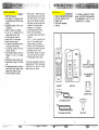
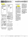
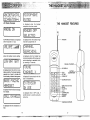
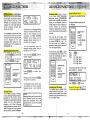
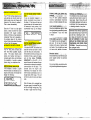
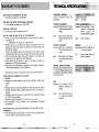
LCD Display Messages
'THE HANDSET
FEATURES
is displayed when the handset
microphone has been muted.
the PHONE ON indicator is displayed
when the phone is in use.
is displayed when the handset ringer
has been programmed off.
ANTENNA
shows the handset volume setting. is displayed when the handset has
lost communication with the base unit
and is attempting to reestablish a link
by scanning all channels.
VOLUME UP
&
DOWN
-
I
LCD DISPLAY
is displayed when the unit is in
a
low-
battery condition. The handset typically
operates for at least
5
minutes after
the low battery indication first appears.
BAlTERY
7
COMPARTMENT
PHONE KEY
is displayed if communication with the
base is reestablished.
TONE
(Temporary
REDIAL
CALLER ID
Tone)
is
displayed when the Base Unit pages
the handset.
MUTE
CLEARIDELETE
is displayed while in OFF mode, if
another phone is currently using the
same line.
PROGRAM
MEMORY
CHARGNG CONTACTS
is displayed when the handset
is
on
hold.

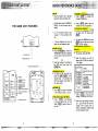
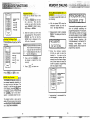
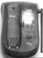
THE
BASE
UNIT FEATURES
AC POWER JACK
---I
PHONE CORD JACK
TONEIPULSE
SELECTOR
1
'
MESSAGE WAITING
-
IN
USE INDICATOR
-
HANDSET CHARGE
-SPARE BATTERY INDICATOR
-
BATTERY COMPARTMENT
:
.....-....
..,.
...-...
i
......:...
-.::..'>a
SET-UP;.
.:-
.
,::,:
'i,'.;,::.
.,
.:
.
.
,
:
.
Plug AC adaptor into a standard
electrical outlet and Base Unit
Set Dial Mode switch to
PULSE or
TONE. The unit is factory set to
TONE.
Let the handset battery pack
charge for
16
hours before first
use.
Connect telephone line cord to
base unit and telephone jack.
MAKING CALLS
Press the@= key. When the
"PHONE ON" indicator is displayed
and you hear a dial tone, dial the
number.
OR
Enter the number to be dialed on
the
LCD and then press the
PHONE)
key.
ANSWERING CALLS
,
i
To answer a call, ress any key
other than
m,
&-),
or the
Volume Keys. The handset will
NOT auto-answer when lifted off
the base cradle.
HANGING UP
Press or place the handset
in the cradle to hang up a call.
I
I
TO PLACE
A
CALL,ON HOLD
I,
Press
(m~)
on the handset
to place an active call on hold.
Press again to return to
the call.
TO
MUTE-A
CALL&^,^^^^^^^^
Press
(m)
to disable the
handset microphone.
Press
(m]
again to return to
normal two way conuersation.
To age from the base, press
*dl
To cancel the PAGE either press
PAGE again on the base or press
OFF on the handset.
€3
The phone should-be OFF.
Enter the number you wish to
store on the
LCD
UD
to a maximum
of
20
digits.
STORING
ENTER MEMORY
(x)
LOCATION
(01
-20)
Press
display
-
(-).
The
LCD
will
"PROGRAM LOCATIONl'
Enter a two digit memory location
(01
..
20),
the unit will store the
number, emit a happy tone to
confirm successful programming
and exit program mode.
TO PAGE THE HANDSET
STORING MEMORY (SPEED) DIAL
NUMBERS

&&&;;
FM.2H
You can use vour
VT
1921 cordless
MAKING
-
-.
-
CALLS .. .-
-..-
-.-.
--
-
To view the time and date of the
call press and hold the
7
@
key.
The time and date will be shown
along with the phone number. You
will see something like:
NOTE: There are two different ways
to dial a number:
phone with services such as Call
Waiting. Simply press the
(PHONE]
key to FLASH the line.
STORlNG
THE PHONE
SHOULD
BE
OFF
1. Press the
(m)
key and wait
for dial tone. Then dial the number
....
...
...I.
...
.
... .
."':
:"':
:"':
.!
...
i i
-.
....
i... ..'i
.!
....:
...,
...:
.....
,
.
.
...m....:%..:
:Jrn-im....:
s...*
...--...-.
:
,
-.
RE
To REDIAL the last number you
you want.
ENTER
PHONE
NUMBER
PRESSF
YOU WIL
SEE
ENTER
MEMORY
LOCATION
(01
-20)
dialed, ress the(P~0NE) key, then
press
(Rk)
.
The phone will
automatically dial the number. The
number will be shown on the display.
As long as the key is held down.
2.
Enter the number onto the display
first, then press the
(ME)
key.
This will dial the number that is
displayed on the LCD after 2
seconds. See "ADVANCED
DIALING" on Page
24
To view other calls, scroll
backwards and forwards by using
the
a
(*)
and
D
(#)
'keys.
The displav can be cleared bv ~ressina
and holdkg the CLEAR~EL key
down until the display clears.
Press the
(PHONE)
key.
To view additional dlgits not
shown on the display, press
the
-r
(9)
key
Press
.
If you make a mistake when dialing,
press to hang up, then press
the PHONE key to get the dial tone
again.
Enter the memory location of the
phone number you wish to dial
(01
...
20). The number will be
displayed on the LCD and will be
dialed.
To exit press
m.
to disableths handset microphone.
Press again to return to
USING.~EDIA~~,
:+IP-
5
:'
:
.
:I
Press the
(PHONE)
key, then
(-0
to automatically redial
out the last number you dialed.
normal operation.
back in the base, or press
(OFF)
on
the handset.
ringing to disable the ringer for the
AN.S~RRJNG~~CALLS;~;~;.&&~
When the Handset rin s, ress any
key other than
m,
&
or the
VOLUME keys to answer your call.
duration of the call.
handset.
Press
(REDIAL)
so that the
number is shown on the display
and then press the
(-1
key.
call on hold.
The LCD will display CALL ON
The volume controls for the handset
HOLD.
pressmagain to return to the
call.
are located on the side of the unit.
Press the
A
(up) or
'lf
(down) keys
to increase or decrease the volume.
Holding either key down will
continuously change the volume
setting. The
earpiece volume level
indicator on the LCD will change
accordingly. There are four volume
levels.
To return to the call, press
(WD)
again
To page from the Base Unit, press
0.
J
The LCD will display BASE PAGING
HANDSET.
To cancel the page, either
press
(PAGE)
a ain on the Base
Unit, or press&on the Handset.
The display will show the most
recent call received.
MEMORY DIALING (SPEED
DIALING)
CID - CALLER ID
HOLD
DISCONNECTING
VOLUME CONTROLS
REDIAL
CLEARING THE DISPLAY
MUTE
RINGER MUTE
HOLD
PAGE/HANDSET LOCATOR

,,*WlypRp,-
".
&.-
>"
~~&~A~~G&~J$~~~>$~$-~~{>&~&~~~+
While you are on a call, you will hear
an alert signal, warning that a second
caller is trying to reach you. CALL
WAITING is a subscription service,
available from most local telephone
service providers. Contact your
provider for details.
If you subscribe to this service linked
with CALLER ID (CID), the name
and/
or phone number of the second caller
can be displayed on the LCD
immediately after hearing the CALL
WAITING alert. For more details, see
CID-CALLER ID.
~witchin~'cails using FLASH,N,,_,
L%
-&
2ii.1-_--..
YI_
-
_.
^..L.
To switch over to the new call,
press thep~o~E>ke~; the first call
Is put on hold.
To switch back to the first call,
press theCK~) key again.
SWITCHING
CALLS
000
0
0
a
TO
SWITCH
OVER
TO
TO
SWITCH
BACK
TO
THE
FIRST CALL
PRESS
@
AGAIN
\-,
Message Waiting
Your
VT
1921
is capable of detecting
a Visual Message Waiting Indication,
generated by many phone service
providers. If you subscribe to Voicemail
service from your local telephone
company, and Visual Message
Waiting Indication
is
provided, the VT
1921
will display the following data to
alert you to new, unplayed messages:
Simultaneously, the Message Waiting
indicator on the Base will flash slowly.
Once you have reviewed your new
messages, the MSG. WAITING
indication on the handset, and the
Message Waiting indicator light on
the Base will be cleared.
You can temporarily clear the
Message Waiting screen. With the
Handset in the OFF mode.
Press and Hold
6x3
until the
handset displays:
Press
(CLRIDEL)
to confirm your
decision.
Pressing any key other than
will cancel the operation.
The Message Waiting indicatipn alert
may reappear, as long as unplayed
messages remain in your Voicemail
box.
NOTE:
Message Waiting works in conjunction
with Voicemail service from many
local phone companies. This is an
optional service. You are not required
to subscribe to it.
Temporary,Toneh&&*
U...._
4
YC
s+~~\>&
La>
If you have rotary (dial-pulse)
telephone service (TONEIPULSE
switch is set to PULSE), this feature
allows you to temporarily switch to
TONE dialing for such purposes as
remote access to answering
machines,
bank;by-phone services,
use of calling cards and other special
services.
First, dial the call normally. Then
activate the Temporary Tone feature
by pressing TONE (the
'
key). You
can then press the numbers or
symbols you need, and your phone will
send the proper signals.
To end the call, press or place
the handset back in the base. The
phone will automatically go back to
rotary (dial-pulse) service.
TEMPORARY
TONE
PRESS
THE
NUMBERS
OR
SYMBOLS
Progra,m-ming
:The
Ringer
$
The handset ringer is capable of four
different types of ringer tones
.
The
following sections detail how to select
different ringer types and how to turn
off the handset ringer.
To select a different ringer type do
the following:
CHANGING
RINGER
TYPES
PRESS
@
PRESS
a
PRESS
00
a
PRESS
Press:
(PROd
Press:
a
Press:
1
for ringer type
1
2
for ringer type
2
3
for ringer type
3
4
for ringer type
4
The handset LCD will show the ringer
type selected, for example
Press
(PROG)
or
(OFF)
to exit.
Turning Off The Ringer
Changing Ringer Types

TURNING OFF
THE
RINGER
PRESS
PRESS
a
PRESS
a
PRESS
@
s-
m,,
"l
2-b
#
i:,
j
To test the present ringer type, do the
following:
Press
(m)
or to exit.
be accessed separately depending on
how long the key is held down. For
example, to clear the last di it entered
on the display, press
theG&0 key
for less than
1
second. Press and hold
the
(c)
key for more than
1
second to completely clear the LCD.
The delete function is also used to
delete CID and memory dial records,
see DELETING STORED NUMBERS,
and DELETING NUMBERS.
Advanced Dialing
,J:~;;,'_+.
There are two different ways to d~al
a number:
1.
Press the
(PHONE)
key and wait
for a dial tone. Then dial the
number you want either manually,
using MEMORY (MEM) dialing,
CID dialing or REDIAL.
2.
Enter the number you wish to dial
on the display first. Then press the
(PHONE)
key. This will dial the
number which is displayed on the
LCD after
2
seconds.
which is shown on the display.
.
If-you do not want to dial the
'.
,:
number
she-wn
on the LCD, it
"
cah 'be bhanaed bv:
Press and hold
(-1
until
the display is cleared, then dial
normally.
or
Press
(OFF)
and start over.
Storing
Memory: (Speed) Dial
2,;;
'.
numbers$!
i",
.cr+!
..:$,.':.I;
:-:I
To program a speed'dial idcation, do
the following:
With the phone OFF, enter the
telephone number you wish to
store. (20 Digits Maximum).
Enter program mode by pressing
(PROGS.
The display will show the
following:
Enter the memorv location
(01..20) you wish to store the
number in.
-
As soon as the
second memory location digit is
entered, the unit will emit a happy
tone (a short series of beeps) to
confirm successful programming
and exit program mode.
STORING
SPEED DIAL
NUMBERS
DIAL
YOUR
PHONE
NUMBER
PRESS
@
PRESS
LOCATION
(01-20)
unsuccessful the
unit will display:
:
i"';
p..i
p..i
'i'
f..
f
i"'.
.
iY
!
i i
.
.i.
i
7
Ci
I"':
!.'.""'.
I
:""
""'
:""
..".
.
iE
'L
j...
!
.......
i i
i
....
:
....
i
i:::.
Unsuccessful programming can result
from not correctly completing the
programming sequence. For example,
if after entering a number on the LCD
and entering program mode,
them
key were pressed instead of entering
a valid memory location, the
"PROGRAMMING INCOMPLETE"
message would appear. If this
message appears, simply repeat the
programming sequence:
Checking The Ringer Type
CLR/DEL Key Function

Press
m,
you're prompted to
enter a speed dial location
number:
Enter a 2 digit location number
(01 -20)
The number stored in that location
will be displayed and immediately
dialed.
Or
Beginning from the OFF mode,
press mfollowed by a 2 digit
location number (01-20).
Press =gain to exit memory
dial mode and leave the number
on the display.
Note that if digits were on the
display prior to entering memory
dial mode, the contents of the
speed dial memory will be ap-
pended to those digits. For exam-
ple, if
1503
was on the LCD and
the conte,nts of the memory
location is 6438981, then the
display would show the following
upon exiting memory dial mode:
Press
(m~),
the number on the
display will be dialed after a 2
second pause.
NOTE:
The ability to temporarily add memory
contents to digits already entered on
the display operates in the same way
for CID and speed dial, memories.
In this way, long distance and area
codes (for example, 1503) can be
entered on the LCD and can preface
numbers recalled from CID memory
before dialing. This is important
because only the last
7
digits of any
number are displayed when dialing
from CID memory.
Changing Stored Numbers
.
To change or'replace a stored number
simply enter the new number on the
display and store it in the memory
location you wish to change.
Deleting Stored Numbers
Press
(MEM).
The display will
change to "SPEED DIAL
LOCATION-
-".
Enter memory location number
(0
1
-20).
Press
(CLEARIDEL)
key. The
display will change to "LOCATION
press mto exit.
NOTE:
Stored numbers are retained in memory
even if the base loses its power or the
handset battery is removed.
Storing Special Codes
YJ
-&,%tXq
To insert a ause in a phone number,
press
&
at the appropriate point
when entering the number on the LCD.
This inserts a 2 second pause. A
"
P
"
appears in the display to show
For longer pauses, press
or more times. Each press
makes the pause
2
seconds longer
and is treated as a stored digit.
If your phone is connected to a PBX,
you can store the PBX access
number and
a
pause before the
phone number. For example, to
store 9-PAUSE-555-1234 in memorv
location 08, do the following:
3.
Dial 5551234
4. Press
(i%iZii$I
5.
Enter 08
Dialing From Memory

NOTE:
You must be in an area where CID
service is available and you mus
subscribe to it to use this feature.
I
Your
VT
1921 cordless phone is
capable of displaying the name and/
or phone number of the person calling,
before you answer the phone.
Subscription to Caller ID service
through your local phone company is
required to utilize this feature.
the received telephone number will be If for 'any
reason the telephone
used. Consequently, you would number of the caller is unavailable, or
actually dial this:
'
if the caller is outside the CID service
If you do not subscribe to the CID service,
the phone will still operate normally
except that the CID information is no
received or displayed.
4
.I...#
..........::...,,
area, the message UNAVAILABLE is
....
I"':
::i.
-.,:...:
..
..;
:"':
I
:
displayed on the LCD.
...
...................
If
you subscribe to alphanumeric (name
&
number) Caller ID service, the calling
party's name and phone number (when
available) will be displayed on the LCD
screen while the phone is ringing.
Y"
.,
,
.
,
Receiving and,storirig
Calls
This unit receives and displays all
CID information,including the caller's
telephone number, the caller's name
and the exact date and time of the call.
The VT 1921 was designed to
'
accommodate this situation. If you
need to temporarily add a long
dlstance prefix and /or area code
(such as 1503) before the CID number,
do the following:
Beginning from the standby mode,
key in the necessary digits. Your
display will look like this:
r--'.
1
.-I
1-1
-2,
If the caller has exercised the option
If you subscribe to numeric (number
only) Caller ID service, the calling
party's phone number (when available)
will be displayed on the LCD screen
while the phone is ringing.
to block his or her number from being
sent, then the display will show
PRIVATE.
The phone sequentially numbers
these call records and retains them in
the unit's CID memory for later review.
These call record numbers are
displayed as the first two digits in the
display. The unit can store up to 50
numbers in its memory.
-
Then, to temporarily add the last
Your VT 1921 cordless phone is also
capable of displaying Caller ID
information in connection with a Call
Waiting signal. If you are on a call, and
receive a Call Waiting alert signal, the
LCD will display the name
and/or
number (when available) of the party
trying to reach you. As above,
subscription to Call Waiting ID service
through your local phone company is
required in order to utilize this feature.
Once the
CID memory is full, any new
call forces a deletion of the oldest call
record.
7
digits only from
a
CID memory,
press
(CID).
If an error
is
detected, then the CID
information is incomplete and will
not be displayed.
"TRANSMISSION
ERROR"
will be displayed on the
LCD screen.
DIALING FROM CID MEMORY
Using the
a
(*)
and
D
(#)
keys,
scroll through the received calls to
locate the number you wish to dial.
NOTE:
Only the last
7
digits of any number
are displayed when dialing from CID
Once you have located the
number ou wish to dial, simply
press
@hll
The last seven
digits will be added to the
numbers already in the LCD, and
the whole number shown below
will be automatically dialed.
For example, when you press and hold
the
7CQ
key to view the phone number,
you would see the following:
The occasional appearance of
"TRANSMISSION ERROR"
on your
display does not indicate a problem
with your unit or your telephone line.
However, if this appears frequently,
you may want to notify your telephone
company.
ID informition may nit be available for
every call you receive. In addition, the
calling party may intentionally block
their name
&
phone number from
being sent.
.....
...I.
....,
.....
.....:
1
....,...I..:
.
....,..'*:
.
i'j...]
i...ii ii...
...
i
m..........
: :
.....
-...:
.....
.:.
CID - CALLER ID
CALL WAITING CALLER ID (TYPE II
CID)
A WORD ABOUT CALLER ID - CID
Special Message Indicators
Out Of Area Calls
Private Calls
Transmission Error

Calls stored in memo can be
reviewed by pressing
b
CID
.
The
display will show the number of the
most recent (CALL
#01).
The top line
of.the display is used to indicate
the memory location number and the
bottom line of the display shows the
name, see below:
There may be' additional characters
in the name which can not be
shown on the current display. Press
the
A
(
9
)
key. This will overwrite
the CID memory location on the top
line to show up to a maximum of
15
alpha characters for the duration
of the key press. The first
12
alpha
characters will be on the top line with
up to
3
additional characters on the
second line.
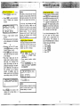
REVIEWING NUMBERS
PRESS-
Press lhe*
&
and
#
V
keys
to scroll
Press and hold Re
7Q
lo view
number
Press
@
lo dial
or
Press
a
to exil
To find out the corresponding phone
number as well as the date and
the call, press and hold
the
time
7
8
1
key. The date and time will
be shown. Releasing the key will again
show the caller's name.
.......
...I.
....
.:
...I.
...............
.:
....
i
*.....
i
...,:
:.i,
.......
'...:'...:'...'
:
...:L:
....:
....
I
.....
:....
...:L:.
i.
Pressing the (a(*) key) displays the
next lower in sequence call record.
Likewise, pressing the
(D(#)
key)
displays the next higher in sequence)
call record. The higher the call number,
the older the call.
To save you time in reviewing call
records, you can "wrap-around" the
call history log. For example, if you
press the
a
(*)
key enough to scroll
back to the first record, pressing it
again will force the display to go to the
very end of the call record.
The LCD will display "-EMPTY-" when
no CID Message was recorded.
DELETING- NUMBER$@:?
*
?
-
Pressing the (cLR/DEL)button delete:
the CID number displayed.
While the phone is in CID mode,
press the
(C~Q
key once to
delete the current call and the
display will show:
"':
E""
I""
.:"
:
....
y
:--.:
1.::
................
I
.mi
I
i
The older CID records will be
moved forward by one location
.
Press and hold the (Cmi
key for more than
2
seconds to
delete the entire contents of CID
memory. The display will show
the following, for a final
confirmation, before the entire CID
memory is erased:
....
"..I
....
...
.
.
IF:^
i...
1
...
Pi
1
...
...I.
..............
i
....
I...........
Pressing any key other than
@-~).ill cancel the operation.
Pressing
@-L)
will confirm
the operation and the display will
then show:
The message will remain on the
display for
2
seconds.
Reviewing Numbers

,,r*.w,..r
a,
..,
~E$&@!JLEREER~ENCE&&~
Your
VT
1921 cordless tele~hone has
auto-channel scan circuitry'which will
detect excess noise and change the
channel of the phone to reduce it.
This is done automatically.
Since the VT 1921 is a fully digital
phone, it does not suffer from noise
associated with regular cordless
phones. At times you may experience
occasional "drop outs", especially at
the extreme edges of the phone's
range. Simply move closer to the base
unit and this will disappear.
J
gpjp$xT&"S"&@RITq
'"o,jli;id
id
L.3.
-*~d.i?.,%.~~*~~-.
~2
Your VT 1921 phone is factorv set
with 16.8 million possible security
codes. This unique security code
al!ows your handset and base to
recognize each other, and minimizes
the possibility of another cordless
phone using your .telephone line.
O~~~OF~~RANGE
INDICATION
-
If the handset is moved to a point
where the base and handset can no
longer communicate, the handset will
display the following:
OUT OF RANGE WHEN PHONE IS
ON-,:.,
,
,,>,,
:
1
%
If you are presently engaged in 'a
phone conversation move closer to
the base. If the base unit does not
communicate with the handset within
25
seconds of losing contact, it will
automatically hang up, and display:
OUTFOF
'RANGEWHEN
'PHONE
IS
0FFks:.:~~?3~;~~~~bt,&$~!,.?
,
If the phoniis
OFF;
$e handset and
base still monitor each other to make
sure that they can communicate.
If
the handset is moved out of range, the
handset will make a series of beeps,
and will then display
"CHANNEL
SERACHING"
on the
LCD.
At
15
second intervals the handset will scan
all channels in an attempt to reestablish
communication with the base. This
process does not require user
intervention; the handset will re-link
with the base automatically once it is
brought back within range. The unit
will then be able to receive and place
calls.
When the base unit is unplugged from
the power supply, the handset will give
the "Out of Range" warning beep. Plug
the base in again and this will stop.
TAKING .,CARE :*OF.&.YO,URJ~TEL;-
EPHONE!.,,;
.*
,:h:',j2:,l;;<
Your VT 1921 cordless telephone
contains sophisticated elec'tronic
parts, so it must be treated with care.
'1
Avoid rough. tygatmgntaSX..
-,
;
;..
.,
Place the handset down gently. Save
the original packing materials to protect
your telephone if you ever need
to ship it.
Your telephone can be damaged if it
gets wet. Do not use the handset
outdoors in the rain, or handle it with
wet hands. Do not install your base
unit near a sink, bathtub or shower.
Electrical storms.
%
,
~lectrical storms can somethes cause
power surges harmful to electronic
equipment.
For your own safety, use caution when
using electric appliances during storms.
Cleaning
y-qur
telep,h>one~ai
.,.&i
B
Your telephone has a durable plastic
casing that should retain its luster for
many years. Clean it only with a soft
cloth slightly dampened with water or
a mild soap. Do not use excess water
or cleaning solvents of any kind.
Remember that electrical appliances
can cause serious injury if used when
you are wet or standing in water.
If
your base unit should fall into water,
DO NOT RETRIEVE IT UNTIL YOU
UNPLUG THE POWER CORD AND
TELEPHONE LINE CORDS FROM
THE WALL.
Then pull the unit out by
the unplugged cords.
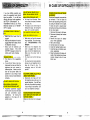
ADDITIONAL OPERATING TIPS
NOISES OR INTERFERENCE
AUTOMATIC SECURITY CODING
MAINTENANCE

If you have difficulty operating your
phone, the suggestions below should
solve the problem. If you still have
difficulty after trying these suggestions,
call VTECH Communications at
1-800-595-951 1 in the
US.
and VTech
Electronics Canada Ltd at 1-800-267-
7377
in Canada.
pugged
Make sure the telephone line cord is
plugged firmly into the base unit and
the telephone wall jack.
Make sure the batteries are
properly charged. If the 'LOW
BATTERY' message is shown, the
battery pack needs charging.
;
.
.ll,',,l'.,
N.~D,IA.~;T,O.NE.~.;~;~;,;.-
.::.:~~~.j.,;:
~;t:!!:,Jj;.<:.a:~,
First check all the suggestions
above.
If you still don't hear a dial tone,
disconnect the base unit from the
telephone jack and connect a
different phone. If there is no dial
tone on that phone either, the
problem is in your wiring or local
service. Call your local telephone
company.
@'4%.rL..\.:.>,-..,-
,
8
i.,"
..,
;~~~~~G~~~~.~I~E,~~~TATI,c,
,OR:
A
.W
~;fi
!~&@wA
L~E,v,E
N&~W.H
E
Y&u&$&!@&T~.E
;-BASE,.~U.NI~~::~;
Household appliances plugged
into the same'circuit as the base
unit can sometimes cause
interference. Try moving the
appliance or the base unit to
another outlet.
"YOU GET -NOISE, STATIC, OR-A
WEAK 'SIGNAL
'
WHEN,;,YOUIRE
AWAY ,FROM THE BASE UNIT.
5'5
You may be' out of range. Either
move close to the base, or relocate
the base unit.
The layout of your home may be
limiting the range. Try moving the
base unit to another position.
THE-HANDSET
DOES
NOT
RING
WHEN YOU RECEIVE A CALL.
.
\.
.-
Make sure you have the handset
ringer activated. To set the ringer,
see
"PROGRAMMING THE
RINGER".
Make sure the telephone line
cord is plugged firmly into the
base unit and the telephone jack.
Make sure the power cord is
plugged in.
You may be too far from the base
unit.
You may have too many extension
phones on your telephone line to
allow all of them to ring. Try
unplugging some of the other
phones.
YOU ,HEAR:OTHER, CALLS WHILE
USING Y0UR:PHONE.S
.::
Disconnect' your base unit from
the telephone jack, and plug in a
regular telephone. If you still hear
other calls, the problem is probably
in your wiring or local service. Call
your local telephone company.
YOU HEAR NOISE INTHEHANDSET,
AND NONE .OF THE KEYS OR
BUlTONS WORK.
-
Make sure the power cord is plugged
in.
COMMON CURE FOR ELECTRONIC
EQUIPMENT
..,,
Electronics, like people, can sometimes
get confused. If the unit does not
seem to be responding normally, then
try putting the handset in the cradle.
If it does not seem to respond after
trying this a few times, do the following
(in the order listed):
1. Disconnect the power to the base.
2. Disconnect (remove) the handset
battery pack.
3.
Remove the base unit battery
pack, where applicable.
4.
Wait a few minutes.
5. Connect power to the base.
6.
Install the handset battery pack.
7.
Install the base unit battery pack,
where applicable.
8. Place the handset in the base unit
cradle. If the handset has not been
recently charged, allow 8 hours
before use.
IN CASE OF DIFFICULTY
THE PHONE DOESN'T WORK AT
ALL
YOU GET NOISE, STATIC OR A
WEAK SIGNAL EVEN WHEN
YOU'RE NEAR THE BASE UNIT
YOU GET NOISE, STATIC OR A
WEAK SIGNAL WHEN YOU'RE
AWAY FROM THE BASE UNIT
THE HANDSET DOES NOT RING
WHEN YOU RECEIVE A CALL
Page is loading ...
Page is loading ...
Page is loading ...
Page is loading ...
Page is loading ...
Page is loading ...
Page is loading ...
-
 1
1
-
 2
2
-
 3
3
-
 4
4
-
 5
5
-
 6
6
-
 7
7
-
 8
8
-
 9
9
-
 10
10
-
 11
11
-
 12
12
-
 13
13
-
 14
14
-
 15
15
-
 16
16
-
 17
17
-
 18
18
-
 19
19
-
 20
20
-
 21
21
-
 22
22
-
 23
23
-
 24
24
-
 25
25
-
 26
26
-
 27
27


