
EPIC | SCARLET | V5.1
DRAGON | MYSTERIUM-X
RED.COM
RED DSMC
OPERATION GUIDE

COPYRIGHT © 2014 RED.COM, INC
RED DSMC OPERATION GUIDE
955-0020_V5.1, REV-L | 2
TABLE OF CONTENTS
Disclaimer 3
Copyright Notice 3
Trademark Disclaimer 3
Compliance Statements 4
Safety Instructions 6
Battery Storage and Handling 7
Shipping Disclaimer 7
Chapter 1: DSMC Overview 8
DRAGON Sensor 8
MYSTERIUM-X
®
Sensor 8
Image Processing 9
HDRx 9
Magic Motion 10
Audio Recording 10
Microphone Level Analog Inputs 10
Line Level Analog Inputs 10
Video Monitoring Outputs 11
Lens Mounts 12
SMPTE Timecode 12
Additional Resources 12
Chapter 2: Components and Modules 13
BRAIN 13
Side SSD Modules 15
DSMC SIDE HANDLE 18
DSMC Modules 20
REDMOTE 32
DSMC Displays 33
Chapter 3: Power the DSMC 36
Power Consumption 36
Power Priority 36
Power Status 36
Power Up 36
Power Down 37
Chapter 4: Graphical User Interface 38
Viewfinder Outputs 38
DSMC SIDE HANDLE 42
REDMOTE 42
Navigate Graphical User Interface 43
Chapter 5: Basic Menus 44
Access Advanced Menus from Basic Menus 44
Edit List Feature 44
Frame Rate (FPS) 44
ISO (Sensitivity) 44
F Stop (T Stop) 45
Exposure 45
White Balance (Color Temperature) 45
Resolution 45
REDCODE 45
Chapter 6: Advanced Menus 46
Settings Menu 46
Media Menu 95
Playback Menu 95
Power Menu 96
HDR Menu 97
Focus Menu 98
Presets Menu 104
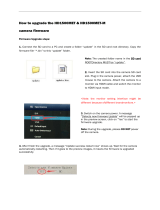
Chapter 7: Upgrade DSMC Firmware 107
Verify Current Camera Firmware 107
Upgrade DSMC Firmware 107
Chapter 8: Audio Subsystem 109
Audio Format 109
Channel Setup 109
Source Selection 109
Channel Modes 109
Audio Recording 110
Peak Meter 110
Data Path 111
HD-SDI/HDMI Embedded Audio 111
Audio During Playback 112
Chapter 9: REDMOTE Operation 114
Overview 114
Control, Connectors and Display 114
Operation 116
Internal Battery 120
Upgrade REDMOTE Firmware 121
Appendix A: Input/Output Connectors 125
SSD Module Connectors 125
Camera BRAIN 125
REDMOTE 134
Appendix B: Supported Lenses 135
Lens Weight and Lens Support 135
DSMC PL Mount Supported Lenses 135
DSMC Canon Mount Supported Lenses 136
DSMC Nikon Mount Supported Lenses 138
DSMC Leica-M Mount Lenses 138
Appendix C: Default Key Functions 139
Appendix D: 3D Setup and Operation 142
Overview 142
Camera Setup 142
Clip Naming Conventions 142
Connecting Cameras 143
Operation 143
Appendix E: Post-Production 144
Monitoring 144
REDCINE-X
®
PRO 144
Appendix F: DSMC Maintenance 145
Cleaning 145
Back Focus Adjustment 146
Appendix G: Troubleshoot Your DSMC 148
Perform a Stress Test 148
Preset Could Not Be Applied 148
Camera Cannot Be Paired to REDMOTE 148
Cannot See Menus on LCD Touchscreen 149
Screen Freezes or Does Not Display 149
Image Appears Grainy 149
Black and White Image 149
Offline Clips and an Extra R3D File 150
Appendix H: Technical Specifications 151

RED DSMC OPERATION GUIDE
COPYRIGHT © 2014 RED.COM, INC
955-0020_V5.1, REV-L | 3
DISCLAIMER
RED has made every effort to provide clear and accurate informa-
tion in these installation instructions, which are provided solely for
the user’s information. While thought to be accurate, the informa-
tion in this document is provided strictly “as is” and RED will not
be held responsible for issues arising from typographical errors or
user’s interpretation of the language used herein that is different
from that intended by RED. All safety and general information is
subject to change as a result of changes in local, federal or other
applicable laws.
RED reserves the right to revise this document and make changes
from time to time in the content hereof without obligation to notify
any person of such revisions or changes. In no event shall RED, its
employees or authorized agents be liable to you for any damages
or losses, direct or indirect, arising from the use of any technical or
operational information contained in this document.
For comments or questions about content in this Operation Guide,
please send a detailed e-mail to [email protected].
COPYRIGHT NOTICE
COPYRIGHT© 2014 RED.COM, INC.
All trademarks, trade names, logos, icons, images, written material,
code, and product names used in association with the accompa-
nying product are the copyrights, trademarks or other intellectual
property owned and controlled exclusively by RED.COM, INC.
TRADEMARK DISCLAIMER
All other company, brand and product names are trademarks or reg-
istered trademarks of their respective holders. RED has no affiliation
to, is not associated or sponsored with, and has no express rights
in third-party trademarks. Distagon is a registered trademark of Carl
Zeiz, Inc. Leica is a regestered trademark of BV Corporation Nether-
lands. Nikkor, is a registered trademark of Nikon Corporation.
EPIC DRAGON 151
EPIC MYSTERIUM-X 153
SCARLET DRAGON 155
SCARLET MYSTERIUM-X 157
DSMC BRAIN Dimensions 159
Appendix I: Menu Map 164

COPYRIGHT © 2014 RED.COM, INC
RED DSMC OPERATION GUIDE
955-0020_V5.1, REV-L | 4
COMPLIANCE STATEMENTS
INDUSTRIAL CANADA EMISSION COMPLIANCE STATEMENTS
This device complies with Industry Canada license-exempt RSS
standards RSS 139 and RSS 210. Operation is subject to the follow-
ing two conditions: (1) this device may not cause interference, and
(2) this device must accept any interference, including interference
that may cause undesired operation of the device.
This Class B digital apparatus complies with Canadian ICES-003.
Le présent appareil est conforme aux CNR d’Industrie Canada ap-
plicables aux appareils radio exempts de licence. L’exploitation est
autorisée aux deux conditions suivantes : (1) l’appareil ne doit pas
produire de brouillage, et (2) l’utilisateur de l’appareil doit accepter
tout brouillage radioélectrique subi, même si le brouillage est sus-
ceptible d’en compromettre le fonctionnement.Cet appareil numéri-
que de la classe B est conforme à la norme NMB-003 du Canada.
FEDERAL COMMUNICATIONS COMMISSION (FCC) STATE-
MENTS
This equipment has been tested and found to
comply with the limits for a Class B digital de-
vice, pursuant to part 15 of the FCC Rules.
These limits are designed to provide reason-
able protection against harmful interference
in a residential installation. This equipment
generates, uses and can radiate radio fre-
quency energy and, if not installed and used
in accordance with the instructions, may cause harmful interference
to radio communications. However, there is no guarantee that inter-
ference will not occur in a particular installation. If this equipment
does cause harmful interference to radio or television reception,
which can be determined by turning the equipment off and on, the
user is encouraged to try to correct the interference by one or more
of the following measures:
Reorient or relocate the receiving antenna.
Increase the separation between the equipment and receiver.
Connect the equipment into an outlet on a circuit different from
that to which the receiver is connected.
Consult the dealer or an experienced radio/TV technician for
help.
In order to maintain compliance with FCC regulations, shielded
cables must be used with this equipment. Operation with non-ap-
proved equipment or unshielded cables is likely to result in interfer-
ence to radio and TV reception. The user is cautioned that changes
and modifications made to the equipment without the approval of
manufacturer could void the users authority to operate this equip-
ment.
NOTE: This device complies with Part 15 of the FCC Rules.
Operations subjected to the following two conditions (1) this device
may not cause harmful interference, and (2) this device must accept
any interference received, including that may cause undesirable in-
terference.
CAUTION: Exposure to Radio Frequency Radia-
tion.
The device shall be used in such a manner that the potential for hu-
man contact is minimized
This equipment complies with FCC radiation exposure limits set
forth for an uncontrolled environment. This equipment should be
installed and operated with a minimum distance of 20 cm between
the radiator and your body.
CAUTION: Regulations of the FCC and FAA
prohibit airborne operation of radio-frequency
wireless devices because there signals could
interfere with critical aircraft instruments.
CAUTION: If the device is changes or modified
without permission from RED, the user may
void his or her authority to operate the equip-
ment.
AUSTRALIA AND NEW ZEALAND STATEMENTS
RED declares that the radio equipment described in this document
comply with the following international standards.
IEC 60065 - Product Safety
ETSI EN 300 328 - Technical requirement for radio equipment
RED declares digital devices described in this document comply
with the following Australian and New Zealand standards.
AS/NZS CISPR 22 – Electromagnetic Interference
AS/NZS 61000.3.2 – Power Line Harmonics
AS/NZS 61000.3.3 – Power Line Flicker
JAPAN STATEMENTS
This is a Class B product based on the
standard of the Voluntary Control Council
for Interference (VCCI) for information tech-
nology equipment. If this equipment is used
near a radio or television receiver in a do-
mestic environment, it may cause radio in-
terference. Install and use the equipment
according to the instruction manual.
EUROPEAN UNION COMPLIANCE STATEMENTS
RED declares that the radio
equipment described in this
document comply with the
R&TTE Directive (1999/5/
EC) issued by the Commis-
sion of the European Com-
munity.
Compliance with this directive implies conformity to the following
European Norms (in brackets are the equivalent international stan-
dards).
EN 60065 (IEC 60065) – Product Safety
ETSI EN 300 328 Technical requirement for radio equipment
ETSI EN 301 489 General EMC requirements for radio equip-
ment.

RED DSMC OPERATION GUIDE
COPYRIGHT © 2014 RED.COM, INC
955-0020_V5.1, REV-L | 5
INFORMATION
Products with the CE marking comply with the EMC Directive
(2004/108/EC) and the Low Voltage Directive (2006/95/EC) issued
by the Commission of the European Community. Compliance with
these directives implies conformity to the following European Prod-
uct Family Standards.
EN 55022 (CISPR 22) – Electromagnetic Interference
EN 55024-1 (CISPR 24) – Electromagnetic Immunity
EN 61000-3-2 (IEC610000-3-2) – Power Line Harmonics
EN 61000-3-3 (IEC610000) – Power Line Flicker
EN 60065 (IEC60065) – Product Safety
WASTE ELECTRICAL AND ELECTRONIC EQUIPMENT (WEEE)
The Waste Electrical and Electronic Equip-
ment (WEEE) mark applies only to countries
within the European Union (EU) and Norway.
This symbol on the product and accompany-
ing documents means that used electrical
and electronic products should not be mixed
with general household waste. For proper
treatment, recovery and recycling, please
take this product to designated collection
points where it will be accepted free of
charge. Alternatively, in some countries you
may be able to return your products to your
local retailer upon purchase of an equivalent
new product.
Disposing of this product correctly will help save valuable resources
and prevent any potential negative effects on human health and the
environment, which could otherwise arise from inappropriate waste
handling. Please contact your local authority for further details of
your nearest designated collection point. Penalties may be appli-
cable for incorrect disposal of this waste, in accordance with you
national legislation.
For business users in the European Union, if you wish to discard
electrical and electronic equipment, please contact your dealer or
supplier for further information.
USAGE RESTRICTIONS FOR PRODUCTS THAT INCORPORATE
REDLINK
Products that fall into this category are denoted
by inclusion of the Class 2 identifier symbol (ex-
clamation mark in a circle) accompanying the CE
Mark on the products regulatory label, example
to the left.
FRANCE
Usage Restrictions - Geographic Area Where Restriction Applies :
France
For mainland France
2.400 - 2.4835 GHz (Channels 1-16) authorized for indoor use
2.400 - 2.454 GHz (Channels 1-10) authorized for outdoor use
Restrictions d’utilisation - Zone géographique où les restrictions
s’appliquent : France
Pour la France métropolitaine
2.400 - 2.4835 GHz (Canaux 1 à 16) autorisé en usage intérieur
2.400 - 2.454 GHz (canaux 1 à 10) autorisé en usage extérieur
NORWAY
This subsection does not apply for the geographical area within a
radius of 20 km from the centre of Ny-Ålesund
Dette gjelder ikke for det geografiske området innenfor en radius av
20 km fra sentrum av Ny-Ålesund
RESPONSIBLE PARTY:
RED Digital Cinema
34 Parker
Irvine, CA 92618
USA

COPYRIGHT © 2014 RED.COM, INC
RED DSMC OPERATION GUIDE
955-0020_V5.1, REV-L | 6
SAFETY INSTRUCTIONS
DO NOT use the camera or accessories near water. Avoid ex-
posing your camera to moisture. The unit is not waterproof,
so contact with water could cause permanent damage to the
unit as well as electric shock and serious injury to the user. DO
NOT use the camera in the rain or under other conditions with
high moisture without appropriate protection, and immediately
remove power source if camera or accessories are exposed to
moisture.
WARNING: To reduce the risk of fire or elec-
tric shock, do not expose the camera to
rain or moisture.
DO NOT expose the DSMC to laser beams, as laser beams may
damage the sensor.
DO NOT expose your camera to excessive vibration or impact
(shock). Be careful not to drop your camera. Internal mecha-
nisms may be damaged by severe shock. Mechanical alignment
of optical elements may be affected by excessive vibration.
ELECTROMAGNETIC INTERFERENCE: The use of devices us-
ing radio or other communication waves may result in the mal-
function or interference with the unit and/or with audio and
video signals.
Clean only using a dry cloth. When cleaning your camera, re-
member that it is not waterproof and moisture can damage
electronic circuitry. DO NOT rinse or immerse any element of
the camera, lens or other accessory, keep them dry at all times.
DO NOT use soaps, detergents, ammonia, alkaline cleaners,
and abrasive cleaning compounds or solvents. These sub-
stances may damage lens coatings and electronic circuitry.
Maintain sufficient ventilation—DO NOT block any ventilation
openings or obstruct cooling fan airflow.
CAUTION: Proper camera ventilation re-
quires a minimum 1/2” (1,25cm) clearance
between the camera ventilation openings
and external surfaces. Verify that objects
that can block the fan intake and ex-
haust ports do not impede airflow. Failure
to permit adequate airflow may result in
overheating of the camera, degraded op-
eration and in extreme situations, damage
to the camera.
DO NOT operate or store near any heat sources such as radia-
tors, heat registers, stoves, or any other apparatus that pro-
duce heat. Store in a protected, level and ventilated place.
Avoid exposure to temperature extremes, damp, severe vibra-
tion, strong magnetic fields, direct sunlight or local heat sourc-
es during storage. Remove any batteries from the camera be-
fore storage. Recommended storage and usage temperatures
for your camera, lenses and other accessories are:
‒ Operating range: 0°C to 40°C (32°F to 104°F)
‒ Storage range: -20°C to 50°C (-4°F to 122°F)
If there are any performance issues with your camera or acces-
sories when operating within this temperature range, please file
a support ticket on support.red.com.
The DSMC SIDE HANDLE, SIDE SSD Module, Rear Modules
and Lens Mount are NOT HOT SWAPPABLE, meaning you can-
not remove or install them while the camera is powered on. Be-
fore installing or removing any of these accessories, you MUST
power down the camera. Failure to do so may result in damage
to the accessory and/or camera BRAIN that will not be covered
under warranty.
DO NOT bypass the third prong of the grounding-type plug on
the power cord of the AC Power Adapter. A grounding-type
plug has two blades and a third “grounding” prong. The third
prong is provided for your safety. A grounding-type plug shall
be connected to an outlet with a protective earthen connec-
tion. If the grounding-type plug does not fit into your outlet,
do not attempt to modify the plug or outlet, consult a qualified
electrician.
Protect all power cords from being pinched, walked on or
driven over by a vehicle. Replace any power cords suspected
of sustaining damage due to crushing or other forms physical
damage.
CAUTION: The power cord plug for the AC
Power Adapter is used as the power dis-
connect. To disconnect all power from the
AC Power Adapter, unplug the power cord
plug from the wall outlet. During use, the
power cord plug should remain easily ac-
cessible at all times.
Lithium Ion batteries may be subject to special handling re-
quirements pursuant to federal and local laws. Please refer to
specific shipping instructions included with your battery re-
garding proper transport of your battery. DO NOT handle your
battery if it is damaged or leaking. Disposal of batteries must
be in accordance with local environmental regulations. For
example, California law requires that all rechargeable batter-
ies must be recycled by an authorized recycle center. Storing
batteries fully charged or in high temperature, conditions may
permanently reduce the life of the battery. Available battery
capacity may also be temporarily lessened after storage in low
temperature conditions.
WARNING: DO NOT expose the battery to
excessive heat.
WARNING: Danger of explosion if an incor-
rect battery is charged with the RED Char-
ger or is used to power the camera and
accessories. Replace only with the same
or equivalent type battery.
CAUTION: Refer all service and repair to
qualified RED service personnel. To reduce
the risk of electric shock, and damage to
the camera or accessories, DO NOT at-
tempt to perform any servicing other than
any procedures that are recommended in
the operating instructions.

RED DSMC OPERATION GUIDE
COPYRIGHT © 2014 RED.COM, INC
955-0020_V5.1, REV-L | 7
BATTERY STORAGE AND HANDLING
WARNING: Failure to read, understand, and
follow these instructions may result in over-
heating, chemical leakage, smoke emission,
fire, or other potentially harmful results.
Always follow proper battery handling and storage practices. Im-
proper handling and/or failure to abide by proper storage instruc-
tions may cause permanent damage to batteries, or degrade battery
charge holding capacity. Improper handling practices or failure to
comply with instructions may also put you at risk.
Lithium-Ion batteries, like the REDVOLT, REDVOLT XL, and RED
BRICK, self-discharge over time. When storing for long periods of
time, store batteries separately from the camera or charger and
remember to charge batteries to a capacity level of 50% to 80%. If
batteries will be stored for long periods of time, RED recommends
that you check the charge level at least once every six (6) months,
and recharge batteries to a capacity level of 50% to 80%.
When not in use, remove the battery from the camera or charger
and store the battery in a cool, dry place. Avoid non-insulated stor-
age areas with fluctuating temperatures, extreme hot temperatures
(such as inside a hot car), corrosive gas, and direct sunlight. The
optimal storage temperature for batteries is between -20°C to 20°C
(-4°F to 68°F).
WARNING: Batteries stored in a depleted
state may self-discharge and lose the ability to
hold a charge.
WARNING: DO NOT use the battery for pur-
poses other than those specificied.
WARNING: If recharging operation fails to
complete even when a specified recharging
time has elapsed, immediately stop further re-
charging.
WARNING: If recharging operation fails to
complete even when a specified recharging
time has elapsed, immediately stop further re-
charging.
DO NOT store batteries in a fully charged state for extended
periods of time.
DO NOT store batteries in a fully depleted state for extended
periods of time.
DO NOT store batteries in the camera, in a camera module, or
in a charger for extended periods of time.
DO NOT store batteries in extreme hot or cold temperatures.
DO NOT store batteries in direct sunlight.
Store the battery in a location where children cannot reach it.
DO NOT use third-party chargers with your RED batteries.
DO NOT disassemble or modify the battery.
DO NOT overcharge batteries. Overcharging may increase in-
ternal temperature beyond the recommended limits and cause
permanent damage to the battery.
DO NOT connect the positive (+) and negative (-) terminals to
a metal object such as a wire.
DO NOT transport or store the battery together with metal ob-
jects such as jewelry, hairpins, etc. as they may generate heat
if they come into contact with the battery.
DO NOT discard the battery into fire or heat.
DO NOT store, use, or recharge the battery near a heat source
such as a fire or a heater.
DO NOT allow the battery to get wet.
DO NOT pierce the battery with pointed or other sharp objects.
DO NOT step on, throw, or strike the battery with a hammer.
DO NOT use a battery that appears to be deformed or dam-
aged.
DO NOT directly solder the battery.
DO NOT put the battery into a microwave oven or a pressur-
ized container.
DO NOT use or subject the battery to intense sunlight or hot
temperatures such as in a car in hot weather.
The battery incorporates built-in safety devices. DO NOT use it
in a location where static electricity may be present.
DO NOT exceed the recharging temperature range of 0˚C to
40˚C (32˚F to 104˚F).
RED recommends that you only use RED chargers to recharge
RED batteries.
If the battery leaks or gives off a bad odor, discontinue use
immediately.
If the battery gives off an odor, generates heat, becomes dis-
colored or deformed, or in any way appears abnormal dur-
ing use, recharging or storage, immediately remove it from the
equipment or battery charger and discontinue use.
If electrolyte begins leaking from the battery and comes into
contact with your skin or clothing, immediately wash it away
with running water. Failure to do this may result in skin inflam-
mation.
If the battery leaks and the electrolyte reaches the eyes, do
not rub them. Instead, rinse the eyes with clean running water
and immediately seek medical attention. Failure to do this may
result in eye injury.
If you find discoloration, a bad odor due to leakage, overheat-
ing and/or other irregularities when using the battery for the
first time, contact your Bomb Squad Representative immedi-
ately.
NOTE: For more information regarding RED
battery charging and instructions for care,
please refer to our Terms and Conditions.
SHIPPING DISCLAIMER
Unless you have been certified to ship dangerous goods, you must
work with a Dangerous Goods, Class 9-certified shipper to assist
you with a shipment that includes a RED BRICK (or other regulated
lithium ion batteries). Please note that applicable laws prohibit the
shipping of batteries that are physically damaged. We urge you to
look into the formal rules and regulations of shipping Class 9 Dan-
gerous Goods prior to preparing your shipment. For more informa-
tion on these regulations, please visit www.iata.org and www.dot.
gov.

COPYRIGHT © 2014 RED.COM, INC
RED DSMC OPERATION GUIDE
955-0020_V5.1, REV-L | 8
Congratulations on your purchase of one of the following RED DSMC
®
Digital Still and Motion Cameras:
EPIC-M RED DRAGON (CARBON FIBER)
EPIC-M
EPIC-X
SCARLET-X
Each RED DSMC BRAIN is equipped with a DRAGON or MYSTERIUM-X sensor.
The RED family of Digital Still and Motion Cameras (DSMC) provide high performance digital imaging over a
wide range of frame rates and optical formats including Super 35mm/APS-H.
DRAGON SENSOR
The new 6K RED DRAGON™ sensor allows you to capture over nine (9) times more resolution than standard
HD. The result is unrivaled detail and impressive native exposure eclipse 35mm film in both latitude and image
density.
The DRAGON sensor is a model for image innovation, leading the way in the evolution of digital cinema technol-
ogy. Boasting industry-leading specs in resolution, frame capture, dynamic range, and color science, the RED
DRAGON sensor raises the bar for digital still and motion cameras, again.
MYSTERIUM-X
®
SENSOR
The MYSTERIUM-X sensor is specifically designed for use with the RED DSMC BRAIN, and in the EPIC it pro-
vides variable frame rate imaging at up to 95 FPS at 5K FF resolution, and up to 400 FPS at 1K WS resolution.
Native color balance for the MYSTERIUM-X sensor is 5,000 KELVIN, but it may be electronically compensated
for any color temperature in the range 1,700 to 10,000 KELVIN. White balance preset values include Tungsten
(3200K) and Daylight (5600K) light sources. The camera may also calculate a color neutralizing White Balance
value on demand by imaging on a standard white or 18% gray card.
The MYSTERIUM-X sensor includes high precision analog to digital conversion, capable of delivering up to 13.5
stops of dynamic range with daylight light sources over a camera sensitivity rating of 320–800 ISO. In HDR
mode, dynamic range can be extended to approximately 18 stops.
EPIC Digital Still
and Motion
Cameras (DSMC)
01
DSMC
OVERVIEW

RED DSMC OPERATION GUIDE
COPYRIGHT © 2014 RED.COM, INC
955-0020_V5.1, REV-L | 9
IMAGE PROCESSING
The digital image received from the sensor is formatted as a pixel defect corrected (but in all other aspects
unprocessed) 16-bit per pixel RAW data frame.
Each RAW frame or sequence of RAW frames in a clip is compressed using proprietary wavelet based RED-
CODE
®
RAW compression, then stored to a RED MINI-MAG or REDMAG 1.8" SSD.
When recorded, the RAW data is independent of any RGB domain color processing such as ISO, White Balance
or other RGB color space adjustments made by the camera operator. These parameters are saved with the
RAW data as reference metadata; that is, color is not burned into the recorded RAW data.
This recording technique permits RGB color processing choices to be deferred to post-production or to be ad-
justed in the field to help a director visualize alternative color treatments, without affecting the recorded RAW
data’s image quality or dynamic range.
The camera’s monitoring path converts RAW sensor data to a white balanced 12-bit depth 1920 x 1080 pixel
RGB 4:4:4 video signal. This signal may be modified using ISO, White Balance or other RGB color space ad-
justments as desired, and is then scaled and gamma-corrected to provide VIEWFINDER, HD-SDI, and HDMI
monitor outputs at 10-bit depth in 4:2:2 YCC or 8-bit depth in 4:4:4 RGB.
Frame guides and other camera data may be added as desired to one or more of the outputs.
NOTE: The REDCINE-X
®
PRO software can create and export .RMD “Look” files which may then be imported as
camera monitor path color processing presets. This information is stored as reference metadata, so that this
color processing choice can be the default value used in post-production. For more information about Look
files, go to “Looks” on page 105.
HDRX
HDRx is an option for extending dynamic range up to 6 stops over the base dynamic range offered by the cam-
era. When enabled, HDRx simultaneously shoots two images of identical resolution and frame rate—a normally
exposed primary track (A-track), and an underexposed secondary track (X-track) whose exposure value reflects
the additional stops of highlight protection desired.
For example, if you select an HDR value of +2 and your primary track exposure is 1/48 sec, the secondary
track exposure will be 2 stops under, or 1/192 sec. The ISO and aperture remain the same for both exposures.
During acquisition and recording, the two tracks are “motion-conjoined”, meaning there is no gap in time be-
tween the two exposures. This is very important to note because if these were traditional alternating exposures,
there would be a time gap between the two tracks that would show up as an undesirable motion artifact. Both
tracks (A and X) are stored in a single .R3D
®
file.
Since there are two exposures in HDRx mode, the camera is recording double the amount of frames each sec-
ond. For example, when shooting at 24 FPS, the camera is recording two 24 FPS tracks, which is the data rate
equivalent of 48 FPS; however, after combining the A and X tracks in post-production, you will see only one 24
FPS blended image sequence.
HDRx provides multiple options for exploitation in post-production.
Blend the two tracks in post tools like REDCINE-X PRO or any other application that supports the SDK to
create Magic Motion
™
. This blending of the two tracks comes with a slider so that you can decide just how
much of each track you want to use. A preview window shows you the combined result of your selection,
or you can view each track individually.
Combine the two tracks using MNMB (More Normal Motion Blur). MNMB is designed to emulate the motion
of a traditional camera with full motion blur. This is a tool created by The Foundry that uses a new motion
estimation algorithm designed specifically for HDRx. The shorter exposure (sharper image) is blended to
match the motion blur of the normal exposure. Again, a preview window shows the combined result of your
selection, or you can view each track individually.
Use the X-track data for motion tracking, then combine the X-track with the A-track, or just motion stabilize
the A-track using the motion analysis data extracted from the X-track.
Export to EXR file format to get a multi-view EXR with both exposures (like a stereo EXR).

COPYRIGHT © 2014 RED.COM, INC
RED DSMC OPERATION GUIDE
955-0020_V5.1, REV-L | 10
NOTE: If you ignore the X-track data, you will have a standard exposure with up to 13.5 stops of dynamic range
just as if you had not enabled HDRx. For this reason, we encourage the A-track exposure to be “normal” as
it provides the most options. If you are tempted to shoot “over-under”, you are then fully committed to using
HDRx and your post-production options are reduced.
NOTE: When recording in HDRx mode, the camera records twice as many frames per second so that the maxi-
mum frame rate or minimum REDCODE ratio, and the maximum record time on your media will be cut in half.
NOTE: HDRx mode can be used with sensor syncing.
MAGIC MOTION
Shooting at 24 FPS and with an 180 degree (1/48 sec) shutter on a film or digital camera may create an opti-
cal illusion we are familiar with, however it is not really the way the eye sees motion. To understand this, ask
someone to stand in front of you and swing their arm over their head from one side to the other. What you would
observe in the recording is a constant motion blur until the arm stopped. What your eye sees though is both
motion blur AND a sharper reference to the arm and hand all along the motion path. MAGIC MOTION provides
such a combination of motion blur (A-track) and a sharper reference (X-track), with the bonus of extreme dy-
namic range not available with any other motion capture camera system.
AUDIO RECORDING
The RED DSMC can record up to two discreet channels of microphone level uncompressed 24-bit, 48 KHz au-
dio (four channels of microphone level or line level audio inputs when equipped with a PRO I/O MODULE), that
are synchronized with video and timecode to a RED MINI-MAG or REDMAG 1.8" SSD.
Input signals are routed via a high quality pre-amplifier and soft clip analog limiter in order to achieve the de-
sired audio reference/recording level and maximize dynamic range.
To assist with audio reference level setup, the camera provides a color-coded Audio Level Meter in the graphi-
cal user interface. Meter range is –52 dBFS to 0 dBFS with audio input type, reference level and audio input
clipping indicators.
Audio monitor output options include a 2-channel headphone output on the DSMC BRAIN and 2-channel line
level analog outputs from the optional PRO I/O MODULE, plus 2-channel and 4-channel 24-bit 48 KHz uncom-
pressed digital audio embedded in the HD-SDI and HDMI outputs.
MICROPHONE LEVEL ANALOG INPUTS
The recording level of a Microphone input is affected by the sensitivity of the microphone and the Gain setting of
the camera’s pre-amplifier. Available pre-amplifier range is 30 dB to 60 dB. The camera operator should choose
a Gain value that aligns the input signal to the 0 dBu reference line drawn on the camera’s Audio Level Meter
(or the 0 VU reference line if operating at that level).
This setting provides up to 30 dB of input signal headroom above reference 0 dBu level before clipping (up to
26 dB above 0 VU reference level) and maximizes the signal to noise ratio of the 24-bit digital recording.
LINE LEVEL ANALOG INPUTS
The recording level of a Line input is affected only by the signal provided by the field production sound mixer
or other external line level source. The sound mixer operator should choose a mixer output level that aligns a
reference tone signal to the 0 dBu (–20 dBFS) reference mark drawn on the camera’s Audio Level Meter, or if
using 0 VU as reference level, a mixer output level that aligns a reference tone signal to the 0 VU (–16 dBFS)
reference mark.
This setting provides up to 24 dB of input signal headroom above reference 0 dBu level before clipping (up to
20 dB above 0 VU reference level) and maximizes the signal to noise ratio of the 24-bit digital recording.

RED DSMC OPERATION GUIDE
COPYRIGHT © 2014 RED.COM, INC
955-0020_V5.1, REV-L | 11
VIDEO MONITORING OUTPUTS
In its default configuration, the RED DSMC can simultaneously support one VIEWFINDER output (suitable for
use by a BOMB EVF
®
, or RED LCD) plus one PROGRAM output and one PREVIEW output (suitable for use by
HDMI or HD-SDI monitors). The various monitor outputs can support a set of overlay graphics including cam-
era GUI, timecode, clip name and framing guides; the specific overlay graphics for each type of output is user
configurable.
The default VIEWFINDER output is the EVF/LCD connector located on the front face of the Side SSD Module.
If neither of these is connected, the VIEWFINDER output can be transferred to either the HDMI output or the
HD-SDI output of the DSMC BRAIN.
All monitors are able to display a variety of features, including:
Surround View
™
, which is an additional lookaround area, visible outside of the recorded image.
Frame Guides, showing common film presentation and television aspects such as 2.40:1 and 16:9.
Focus, aided by high display resolution, 1:1 Focus Check function, and false color overlay.
Exposure, aided by dual zebra indicators, RAW “traffic lights”, and RGB histogram.
System information including current frame rate, ISO rating, shutter speed, color temperature, record reso-
lution, record quality, clip name, timecode value, and the remaining battery and media capacity.
BOMB EVF (LCOS) AND BOMB EVF (OLED)
The BOMB EVF (LCOS) and BOMB EVF (OLED) are high-definition, lightweight viewfinders that align quality
performance with compact form factor.
For applications where use of an attached RED EVF or RED LCD is not desired, such as when working on a
crane, the VIEWFINDER/MENU output can be transferred to the HD-SDI or HDMI outputs, supporting remote
camera monitoring up to 200 ft away.
RED TOUCH LCD
The RED TOUCH LCD pixel progressive scan color display allows you to view your image and navigate through
menu settings using touchscreen functionality.
For applications where use of an attached RED EVF or RED LCD is not desired, such as when working on a
crane, the VIEWFINDER/MENU output can be transferred to the HD-SDI or HDMI outputs, supporting remote
camera monitoring up to 200 ft away.
NOTE: DO NOT use the RED LCD as a handle to lift or carry the DSMC. Damage to the RED LCD or other com-
ponents of the DSMC system caused by using the RED LCD as a handle is not covered under warranty.
NOTE: The RED LCD swivel axis has a total range of adjustment of approximately 360˚ (180˚ clockwise or coun-
terclockwise from the nominal “rear-facing” display orientation). The range of adjustment for the tilt axis is ap-
proximately 180˚. At the end of the adjustment range are internal “hard stops” for both axes. Once the swivel
or tilt hard stops have been reached, IMMEDIATELY STOP APPLYING FORCE TO THE LCD. Continuing to
apply force after reaching the internal stops may damage the friction hinge. Damage to the RED LCD or other
components of the DSMC system caused by using excessive force to rotate the RED LCD is not covered under
warranty.
HD-SDI
A 720p or 1080p progressive scan output suitable for monitoring or recording to an external VTR or DDR de-
vice. May be configured for 10-bit LIN (VIDEO) or 10-bit LOG (FILM) encoded data.
HDMI
A 720p or 1080p progressive scan output suitable for monitoring via a PC monitor or most HDTV displays.

COPYRIGHT © 2014 RED.COM, INC
RED DSMC OPERATION GUIDE
955-0020_V5.1, REV-L | 12
LENS MOUNTS
The RED DSMC comes with a DSMC TI PL MOUNT, and may be configured with mounts and 19 mm rods to
accommodate most cinematography lenses, matte boxes, and follow focus systems. Adaptors for 15 mm offset
studio and 15 mm lightweight rods are also available.
Other lens mounts, including the DSMC CANON MOUNT, are available, permitting the use of Canon EF and
EF-S photographic lenses. The DSMC CANON MOUNT can report lens iris, focus, and zoom data when mated
to an electronically supported lens. In addition, iris and manual or auto-focus settings may be controlled from
the camera.
Lens mounts can be changed out in the field; however, it is highly recommended that this be performed in a
dust-free environment, as the optical path will be exposed to the elements during this process.
SMPTE TIMECODE
Time Code (TC) is a SMPTE timecode track that synchronizes to the camera’s high precision internal clock,
or if operated in Jam Sync mode, referencing an externally supplied SMPTE master timecode signal. TC is a
sequential code that is continuous from frame to frame, but is discontinuous from clip to clip.
Edge Code (EC) is a SMPTE timecode track that always starts at 1.00.00.00 on the first frame recorded to the
digital media. It is a sequential code that is continuous from frame to frame and also continuous from clip to
clip. EC is equivalent to RUN RECORD, which is commonly found on broadcast cameras.
Irrespective of the timecode mode selected, once recording starts the camera’s timecode counter will update at
the same instantaneous frame rate as the recording. This ensures that a valid SMPTE timecode value is created
for every frame in the clip, eliminating any timecode count jumps that could affect playback or editing.
If operating in Jam Sync mode referenced to an external timecode source, the clip’s master time reference point
is the first frame of the recorded clip.
ADDITIONAL RESOURCES
The following resources offer additional information about RED, the DSMC system, and the RED community:
RED.com: Check the official RED website for the latest information about RED products.
RED Learn Articles: RED offers in-depth technical articles about RED cameras, post-production, and digital
cinematography.
RED.com/downloads: Go to the RED Downloads page to download the latest firmware, operation guides,
and post-production software.
Support.red.com: Check the RED SUPPORT site for FAQs, or to file a support ticket.
Reduser.net: Discuss all things RED on the REDUSER third-party forum.
In-Camera Help: Select the Help button on an in-camera screen to open up the help for that screen.

COPYRIGHT © 2014 RED.COM, INC
RED DSMC OPERATION GUIDE
955-0020_V5.1, REV-L | 13
This section provides an overview of the DSMC components and modules.
WARNING: The DSMC SIDE HANDLE, Side SSD Module, rear modules and Lens Mount are NOT HOT SWAP-
PABLE, meaning you cannot remove or install them while the camera is powered on. Before installing or remov-
ing any of these accessories, you MUST power down the camera. Failure to do so may result in damage to the
accessory and/or camera BRAIN that will not be covered under warranty.
BRAIN
EPIC BRAIN
02
COMPONENTS
AND MODULES

COPYRIGHT © 2014 RED.COM, INC
RED DSMC OPERATION GUIDE
955-0020_V5.1, REV-L | 14
BRAIN LEDS
LED COLOR/FLASHING DESCRIPTION
Power Status LED
(PWR)
Red Power present; camera off
Yellow Power present; camera booting
Green Power present; camera on
Green flashing Power present; running on battery
Yellow flashing Power present; 5–10 minutes of
battery time left
Red flashing Power present; less than 5 minutes
of battery time left
Record Status LED
(REC)
Off No media present
Green Ready to record
Red Recording
Red slow flashing Recording; 25% media left
Red fast flashing Recording; 5% media left
Yellow Finalizing
Power Status LED (PWR)
and Record Status LED (REC)
Both green flashing Firmware update in progress
Both red flashing Firmware update failing

RED DSMC OPERATION GUIDE
COPYRIGHT © 2014 RED.COM, INC
955-0020_V5.1, REV-L | 15
SIDE SSD MODULES
RED offers the following side SSD modules:
RED MINI-MAG Side SSD Module
Carbon Fiber RED MINI-MAG Side SSD Module
DSMC 1.8" SSD Side Module
DSMC 1.8" SSD Side Module (DRAGON)
Carbon Fiber DSMC 1.8" SSD Side Module (DRAGON)
For more information about installing and using the side SSD modules, see the DSMC Media Operation Guide
available at www.red.com/downloads.
RED MINI-MAG SIDE SSD MODULE
RED offers the following RED MINI-MAG modules:
RED MINI-MAG Side SSD Module: Mounts to any standard aluminum DSMC BRAIN.
Carbon Fiber RED MINI-MAG Side SSD Module: Mounts to any carbon fiber DSMC BRAIN, and is only available
with a carbon fiber DSMC BRAIN.
Each RED MINI-MAG module attaches to the DSMC so that you can mount a RED MINI-MAG to your camera.
Each RED MINI-MAG module has the same EVF/LCD LEMO connector, user keys, and REC button as the
DSMC 1.8" SSD Side Module.
WARNING: The RED MINI-MAG modules are NOT HOT SWAPPABLE, meaning you cannot remove or install the
modules while the camera is powered on. Before installing or removing the modules you MUST power down the
camera. Failure to do so may result in damage to the module or DSMC that will not be covered under warranty.
RED MINI-MAG
Side SSD Module

COPYRIGHT © 2014 RED.COM, INC
RED DSMC OPERATION GUIDE
955-0020_V5.1, REV-L | 16
DSMC 1.8" SSD SIDE MODULE
RED offers the following DSMC 1.8" SSD Side Modules:
DSMC 1.8" SSD Side Module: Mounts to any standard aluminum DSMC BRAIN.
DSMC 1.8" SSD Side Module (DRAGON): Mounts to a DSMC with a RED DRAGON sensor, and is only available
with a DSMC with a RED DRAGON sensor.
Carbon Fiber DSMC 1.8" SSD Side Module (DRAGON): Mounts to a carbon fiber DSMC BRAIN, and is only avail-
able with a carbon fiber DSMC BRAIN.
Each DSMC 1.8" SSD Side Module attaches to the DSMC so that you can mount a REDMAG 1.8" SSD to your
camera.
Each DSMC 1.8" SSD Side Module has the same EVF/LCD LEMO connector, user keys, REC button, and LED
as the RED MINI-MAG Side SSD Module.
WARNING: The DSMC 1.8" SSD Side Module is NOT HOT SWAPPABLE, meaning you cannot remove or install
the module while the camera is powered on. Before installing or removing the module you MUST power down
the camera. Failure to do so may result in damage to the module or DSMC that will not be covered under war-
ranty.
SIDE SSD MODULE CONTROLS
This section describes the controls for all of the side SSD modules.
CONTROL DESCRIPTION
User Key 1 Programmable key
User Key 1 + 2 Press: Eject Media
User Key 2 Programmable key
User Key 1 + 2 Press: Eject Media
REC button Programmable key
Full Press: Record Toggle
Half Press: AF Start
DSMC 1.8" SSD Side Module
(Rear and Front)

RED DSMC OPERATION GUIDE
COPYRIGHT © 2014 RED.COM, INC
955-0020_V5.1, REV-L | 17
SIDE SSD MODULE LEDS
This section describes the LED for all of the side SSD modules.
LED COLOR/FLASHING DESCRIPTION
Media Indicator LED Off No media present
Green Ready to record
Red Recording
Red slow flashing Recording; 25% media left
Red fast flashing Recording; 5% media left
Yellow Finalizing
Yellow flashing Accessing media (for example,
when formatting)

COPYRIGHT © 2014 RED.COM, INC
RED DSMC OPERATION GUIDE
955-0020_V5.1, REV-L | 18
DSMC SIDE HANDLE
The DSMC SIDE HANDLE provides the following:
A battery compartment for one REDVOLT battery.
An LCD display that shows key camera parameter values.
Many programmable user keys and buttons. For a full list of all DSMC SIDE HANDLE user keys and their
default actions, go to “Default Key Functions” on page 139.
DSMC SIDE HANDLE
Front (left), DSMC SIDE
HANDLE Rear (right)
DSMC SIDE HANDLE (Top)

RED DSMC OPERATION GUIDE
COPYRIGHT © 2014 RED.COM, INC
955-0020_V5.1, REV-L | 19
INSTALL DSMC SIDE HANDLE
WARNING: The DSMC SIDE HANDLE is NOT HOT SWAPPABLE, meaning you cannot remove or install the DSMC
SIDE HANDLE while the camera is powered on. Before installing or removing the DSMC SIDE HANDLE, you
MUST power down the camera. Failure to do so may result in damage to the DSMC SIDE HANDLE or DSMC
that will not be covered under warranty.
REQUIRED TOOL: T10 Torx
®
driver
1. Power down the camera.
2. Use a T10 Torx driver to remove the single screw located at the bottom of the BRAIN side plate (if installed).
3. Rotate the BRAIN side plate upwards to disengage the lip at the top of the side plate from the camera
BRAIN, and remove the BRAIN side plate.
4. Insert the lip at the top of the DSMC SIDE HANDLE into the area where the lip from the BRAIN side plate
was installed.
5. Press the DSMC SIDE HANDLE down flush along side of camera BRAIN.
6. Rotate the thumbscrew upward while applying steady pressure until tight.
REMOVE DSMC SIDE HANDLE
WARNING: The DSMC SIDE HANDLE is NOT HOT SWAPPABLE, meaning you cannot remove or install the DSMC
SIDE HANDLE while the camera is powered on. Before installing or removing the DSMC SIDE HANDLE, you
MUST power down the camera. Failure to do so may result in damage to the DSMC SIDE HANDLE or DSMC
that will not be covered under warranty.
1. Power down the camera.
2. Rotate the thumbscrew downward until the DSMC SIDE HANDLE detaches from the camera body.
3. Pull the bottom of the DSMC SIDE HANDLE away from the BRAIN to disengage the lip at the top of the
DSMC SIDE HANDLE away from the camera BRAIN.
4. Remove the DSMC SIDE HANDLE from the camera.

COPYRIGHT © 2014 RED.COM, INC
RED DSMC OPERATION GUIDE
955-0020_V5.1, REV-L | 20
DSMC MODULES
WARNING: The DSMC modules are NOT HOT SWAPPABLE, meaning you cannot remove or install the modules
while the camera is powered on. Before installing or removing modules, you MUST power down the camera.
Failure to do so may result in damage to the modules or DSMC that will not be covered under warranty.
PRO I/O MODULE
The PRO I/O MODULE brings together the essential I/O connections into one module, providing a central hub
for professional audio and video components.
Centralized ports make it easy to manage connections and cables.
LCD/EVF port allows you to connect an additional RED LCD or EVF.
Customize triggers and interface with third-party GPIO and RS232 control devices using RED PRO I/O
cables.
Attach an additional DSMC module or a REDMOTE to the back of the PRO I/O MODULE for additional ex-
pansion.
Internal cooling system maintains appropriate operating temperature.
PRO I/O MODULE
Page is loading ...
Page is loading ...
Page is loading ...
Page is loading ...
Page is loading ...
Page is loading ...
Page is loading ...
Page is loading ...
Page is loading ...
Page is loading ...
Page is loading ...
Page is loading ...
Page is loading ...
Page is loading ...
Page is loading ...
Page is loading ...
Page is loading ...
Page is loading ...
Page is loading ...
Page is loading ...
Page is loading ...
Page is loading ...
Page is loading ...
Page is loading ...
Page is loading ...
Page is loading ...
Page is loading ...
Page is loading ...
Page is loading ...
Page is loading ...
Page is loading ...
Page is loading ...
Page is loading ...
Page is loading ...
Page is loading ...
Page is loading ...
Page is loading ...
Page is loading ...
Page is loading ...
Page is loading ...
Page is loading ...
Page is loading ...
Page is loading ...
Page is loading ...
Page is loading ...
Page is loading ...
Page is loading ...
Page is loading ...
Page is loading ...
Page is loading ...
Page is loading ...
Page is loading ...
Page is loading ...
Page is loading ...
Page is loading ...
Page is loading ...
Page is loading ...
Page is loading ...
Page is loading ...
Page is loading ...
Page is loading ...
Page is loading ...
Page is loading ...
Page is loading ...
Page is loading ...
Page is loading ...
Page is loading ...
Page is loading ...
Page is loading ...
Page is loading ...
Page is loading ...
Page is loading ...
Page is loading ...
Page is loading ...
Page is loading ...
Page is loading ...
Page is loading ...
Page is loading ...
Page is loading ...
Page is loading ...
Page is loading ...
Page is loading ...
Page is loading ...
Page is loading ...
Page is loading ...
Page is loading ...
Page is loading ...
Page is loading ...
Page is loading ...
Page is loading ...
Page is loading ...
Page is loading ...
Page is loading ...
Page is loading ...
Page is loading ...
Page is loading ...
Page is loading ...
Page is loading ...
Page is loading ...
Page is loading ...
Page is loading ...
Page is loading ...
Page is loading ...
Page is loading ...
Page is loading ...
Page is loading ...
Page is loading ...
Page is loading ...
Page is loading ...
Page is loading ...
Page is loading ...
Page is loading ...
Page is loading ...
Page is loading ...
Page is loading ...
Page is loading ...
Page is loading ...
Page is loading ...
Page is loading ...
Page is loading ...
Page is loading ...
Page is loading ...
Page is loading ...
Page is loading ...
Page is loading ...
Page is loading ...
Page is loading ...
Page is loading ...
Page is loading ...
Page is loading ...
Page is loading ...
Page is loading ...
Page is loading ...
Page is loading ...
Page is loading ...
Page is loading ...
Page is loading ...
Page is loading ...
Page is loading ...
Page is loading ...
Page is loading ...
Page is loading ...
Page is loading ...
Page is loading ...
Page is loading ...
Page is loading ...
-
 1
1
-
 2
2
-
 3
3
-
 4
4
-
 5
5
-
 6
6
-
 7
7
-
 8
8
-
 9
9
-
 10
10
-
 11
11
-
 12
12
-
 13
13
-
 14
14
-
 15
15
-
 16
16
-
 17
17
-
 18
18
-
 19
19
-
 20
20
-
 21
21
-
 22
22
-
 23
23
-
 24
24
-
 25
25
-
 26
26
-
 27
27
-
 28
28
-
 29
29
-
 30
30
-
 31
31
-
 32
32
-
 33
33
-
 34
34
-
 35
35
-
 36
36
-
 37
37
-
 38
38
-
 39
39
-
 40
40
-
 41
41
-
 42
42
-
 43
43
-
 44
44
-
 45
45
-
 46
46
-
 47
47
-
 48
48
-
 49
49
-
 50
50
-
 51
51
-
 52
52
-
 53
53
-
 54
54
-
 55
55
-
 56
56
-
 57
57
-
 58
58
-
 59
59
-
 60
60
-
 61
61
-
 62
62
-
 63
63
-
 64
64
-
 65
65
-
 66
66
-
 67
67
-
 68
68
-
 69
69
-
 70
70
-
 71
71
-
 72
72
-
 73
73
-
 74
74
-
 75
75
-
 76
76
-
 77
77
-
 78
78
-
 79
79
-
 80
80
-
 81
81
-
 82
82
-
 83
83
-
 84
84
-
 85
85
-
 86
86
-
 87
87
-
 88
88
-
 89
89
-
 90
90
-
 91
91
-
 92
92
-
 93
93
-
 94
94
-
 95
95
-
 96
96
-
 97
97
-
 98
98
-
 99
99
-
 100
100
-
 101
101
-
 102
102
-
 103
103
-
 104
104
-
 105
105
-
 106
106
-
 107
107
-
 108
108
-
 109
109
-
 110
110
-
 111
111
-
 112
112
-
 113
113
-
 114
114
-
 115
115
-
 116
116
-
 117
117
-
 118
118
-
 119
119
-
 120
120
-
 121
121
-
 122
122
-
 123
123
-
 124
124
-
 125
125
-
 126
126
-
 127
127
-
 128
128
-
 129
129
-
 130
130
-
 131
131
-
 132
132
-
 133
133
-
 134
134
-
 135
135
-
 136
136
-
 137
137
-
 138
138
-
 139
139
-
 140
140
-
 141
141
-
 142
142
-
 143
143
-
 144
144
-
 145
145
-
 146
146
-
 147
147
-
 148
148
-
 149
149
-
 150
150
-
 151
151
-
 152
152
-
 153
153
-
 154
154
-
 155
155
-
 156
156
-
 157
157
-
 158
158
-
 159
159
-
 160
160
-
 161
161
-
 162
162
-
 163
163
-
 164
164
-
 165
165
-
 166
166


Red Digital Cinema Scarlet X 5.1 User manual
- Type
- User manual
Ask a question and I''ll find the answer in the document
Finding information in a document is now easier with AI
Related papers
-
Red Digital Cinema Scarlet X 5.2 User manual
-
-
-
-
-
RED One 31.6.16 - 2011 Owner's manual
-
-
RED Epic - 4.0 2013 Owner's manual
-
-
Other documents
-
Voyager WVSXM43 Operating instructions
-
-
 Ambient NanoLockit User manual
-
 Meiji Techno HD1500MET & HD1500MET-M Operating instructions
-
-
Seagate SSD User guide
-
Wooden Camera 153250 User manual
-
-
Icon 16A92 Replacement Manual
-
Nikon Z 50 User manual

