Icron EL5363 HDMI + USB 2.0 User guide
- Category
- Network extenders
- Type
- User guide
Icron EL5363 HDMI + USB 2.0
The Icron EL5363 HDMI + USB 2.0 Extender is a high-performance KVM extender that allows you to extend both HDMI and USB 2.0 signals up to 100 meters (330 feet) over a single CAT5e/6/7 cable. This makes it an ideal solution for a wide range of applications, such as:
- Digital signage: Extend HDMI and USB signals to remote displays for digital signage applications.
- Home theater: Extend HDMI and USB signals to a remote TV or projector for a home theater experience.
- Video conferencing: Extend HDMI and USB signals to a remote conference room for video conferencing.


-
 1
1
-
 2
2
-
 3
3
-
 4
4
-
 5
5
-
 6
6
-
 7
7
-
 8
8
-
 9
9
-
 10
10
-
 11
11
-
 12
12
-
 13
13
-
 14
14
-
 15
15
-
 16
16
-
 17
17


Icron EL5363 HDMI + USB 2.0 User guide
- Category
- Network extenders
- Type
- User guide
Icron EL5363 HDMI + USB 2.0
The Icron EL5363 HDMI + USB 2.0 Extender is a high-performance KVM extender that allows you to extend both HDMI and USB 2.0 signals up to 100 meters (330 feet) over a single CAT5e/6/7 cable. This makes it an ideal solution for a wide range of applications, such as:
- Digital signage: Extend HDMI and USB signals to remote displays for digital signage applications.
- Home theater: Extend HDMI and USB signals to a remote TV or projector for a home theater experience.
- Video conferencing: Extend HDMI and USB signals to a remote conference room for video conferencing.
Ask a question and I''ll find the answer in the document
Finding information in a document is now easier with AI
Related papers
-
Icron EL5200 HDMI + USB 2.0 User guide
-
-
-
-
-
-
Icron USB 2.0 Ranger 2301GE-LAN Quick start guide
-
-
-
Other documents
-
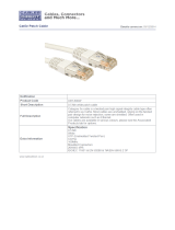 Cables Direct URT-600W Datasheet
-
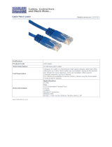 Cables Direct URT-600B Datasheet
-
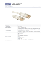 Cables Direct URT-600-HW Datasheet
-
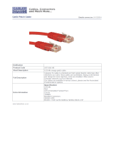 Cables Direct URT-600-HR Datasheet
-
Binary B-100-USB1-CATX Quick start guide
-
B&B Electronics 00-00234 Datasheet
-
Extreme Networks WiRanger User manual
-
Roline USB 2.0 Extender over RJ-45, max. 50m User manual
-
StarTech.com dvi over cat5e/6 kvm extender User manual
-
FSR USB-EXT-1 Owner's manual


