
Spinner
®
V
Spinner
®
Pro
Spinner
®
Elite
Spinner
®
NXT
STAR TRAC
14410 MYFORD ROAD,
IRVINE, CA 92606 USA
S
TAR
T
RAC
F
ITNESS™
S
PINNER
®
B
IKES
U
SER'S MANUAL


Introduction …………………………………………………………………………………………
3
Safety Instructions ………………………………………………………………………………
4
Spinner
®
NXT/Elite/Pro/V Assembly and Setup ………………………………………………
5-14
Spinner
®
V Assembly and Setup …………………………………………………………….. 5-7
Spinner
®
NXT Assembly and Setup …………………………………………………………. 8-11
Spinner
®
Elite / Pro Assembly and Setup …………………………………………………….
12-14
Testing the Bike …………………………………………………………………………………….
15
Instructions for Use ………………………………………………………………………………..
16-19
Seat Adjustments ……………………………………………………………………………...
16-17
Handlebar Adjustments ………………………………………………………………………. 18
Pedal Strap Adjustment ………………………………………………………………………. 18
Resistance Control …………………………………………………………………………… 19
Smart Release™ System ……………………………………………………………………...
19
Training Information ……………………………………………………………………………….
20
User Information ……………………………………………………………………………………
21-25
Bike Setup ……………………………………………………………………………………. 21
Hand Positions ……………………………………………………………………………….. 22
Riding Positions ……………………………………………………………………………… 22
Stretching …………………………………………………………………………………….. 23-24
Heart Rate Guidelines ………………………………………………………………………...
25
Maintenance …………………………………………………………………………………………
26-30
Moving and Leveling ………………………………………………………………………… 26
Preventive Maintenance ……………………………………………………………………… 26-27
Adjustments ………………………………………………………………………………….. 28-29
Parts Replacement ……………………………………………………………………………. 30

This manual will acquaint you with the assembly, operation and maintenance of your Spinner
®
indoor cycling bike.
This manual provides information and instructions for the following Spinner
®
indoor cycling bike models:
•
7060 Series - Spinner
®
V
manufactured by STAR TRAC®
• 7070 Series - Spinner
®
Pro manufactured by STAR TRAC®
• 7080 Series - Spinner
®
Elite manufactured by STAR TRAC®
• 7090 Series - Spinner
®
NXT manufactured by STAR TRAC®
Be sure to read and follow the information and instructions for your specific model before assembly, using or servicing your indoor cycling bike.
WARNING
Your Spinner
®
indoor cycling bike is designed for aerobic exercise. Please check with your physician before beginning any exercise program.
Do not push yourself to excess. Stop if you feel faint, dizzy or exhausted. Use common sense when exercising on the bike.
STAR TRAC® is a registered trademark of STAR TRAC® .
Spin
®
, Spinner
®
, Spinning
®
and the Spinning logo are registered trademarks of Mad Dogg Athletics, Inc.
Smart Release™ is a registered trademark of Nautilus, Inc.
SPD is a registered trademark of Shimano American Corporation.

INSTRUCTIONS
The following fitness safeguards and operating precautions are directed to purchasers and users of Spinner
®
indoor cycling bikes. Club
Managers should ensure that members and fitness staff are trained to follow these same instructions. Failure to follow these safeguards
may result in injury or serious health risk.
Ensure that adjustment knobs (seat height, seat fore-and-aft, and handlebar) are properly secured and do not interfere with range of motion
during exercise.
Children under the age of 16 should not ride the Spinner bike. The bike mechanism and ergonomics are designed for adult use only.
Do not insert any object, hands or feet into any openings, or expose hands, arms or feet to the drive mechanism or other potentially moving
part of the bike.
The maximum weight for individuals riding the Spinner bike should not exceed 350 pounds (159 kilograms).
Spinner bikes have a weighted flywheel and a fixed gear. This means that in order to stop, you must gradually slow your pedal strokes rather
than stopping abruptly. If you do need to stop immediately, push down on the resistance knob. Do not dismount the bike or remove your feet
from the pedals until both the pedals and the flywheel have stopped completely. Failure to comply may lead to loss of control and serious
injury.
After exercising, turn the resistance knob to increase resistance so the pedals will not rotate freely and potentially injure someone.
If at any time you feel dizzy or have difficulty breathing, gradually stop pedaling and carefully dismount the bike.
Listen to your body, ride at your own pace and set your bike’s resistance at the level that feels right for you.
Keep children and pets away from the bike whenever it's in use.
Never turn the pedal crank arms by hand. Stay hydrated. Drink water throughout your ride as needed.
Always keep some resistance on the flywheel.
Stay in control by executing all core movements and hand positions at a slow pace before attempting to increase your speed. Do not attempt
to ride the bike in a standing position at a high RPM until you have practiced at slower speeds.
Focus on form, posture and making smooth transitions between movements.
Do not use the bike without proper footwear. Never operate the bike with bare feet.
Never remove your feet from the pedals while still in motion. Prevent your feet from coming out of the toe clip or shoe cage by keeping shoe
laces tucked in and foot straps pulled snug around your shoe. If your foot does become disengaged, push down on the resistance knob to stop
the flywheel’s motion.

ASSEMBLY AND SETUP
SPINNER
®
V ASSEMBLY AND SETUP
Use the following procedures to unpack and assemble your
SPINNER
®
V.
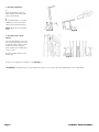
UNPACKING
Position the shipping carton so the “Heavy End” logo is located at the bottom. Open the top of the carton and fold back all four
flaps. Carefully tilt the box forward so that the box may be lifted to expose the bike. Remove all parts from the shipping carton
and foam inserts, and verify that the following parts are included in your shipment:
V-bike Parts List
Description Qty. Description Qty.
Main Frame Assembly (not shown) 1 Tension Handles w/Washers 2
Handlebar 1 Tension Handles w/o Washers 2
Seat 1 Water Bottle Brackets 2
Handlebar Post 1 8mm x 70mm (long) w/Washer and Nuts 2
Seat Post 1 8mm x 60mm (short) w/o Washer and Nuts 2
Back Leg 1 Allen Wrenches, Metric 2
Front Leg 1 Multi-Purpose Wrench 1
Leveling Adjusters (pre-installed) 4
Pedals (set of two) 1
Spare Parts Kit
(includes brake pad and pedal straps)
1
Spare Parts Kit- Save the box of spare parts in a safe place so you have service parts when needed in the future.
Take time now to enter your Spinner
®
V
serial number in the space below (serial number is located on the bottom cross
member). If parts are missing, or if you have any operational questions, please call Star Trac’s Service department at (800) 503-
1221; have your serial number ready.
Serial No._____________________________________________
NOTE: If you are missing any of the parts listed above, inspect the packing material and the box for items that may have been overlooked.
If parts are missing, or if you have any product questions, please call Star Trac’s Service Department at (800) 503-1221, please have your Spinner’s
serial number ready.
CAUTION: Damage to the bike during assembly is not covered as part of the limited Star Trac® warranty. Take care not to drop or lean the bike on
the handle bar pop-pin. Carefully stand the bike up in the normal upright position on a stable surface so it will not tip over during assembly.

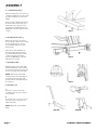
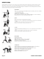
ASSEMBLY
1. Install the Back Leg
Place the back leg in position at the rear
of the bike, aligning the two holes in the
leg with the mating holes in the frame
bracket.
Insert two 8mm x 70mm bolts through
the frame bracket and back leg, and
install a flat washer and nut on each
bolt. Using the #5 Allen Wrench and
Multi-Purpose Wrench, tighten the nuts
securely.
Step 1
2. Installing the Front Leg
Place the front leg in position at the
front of the bike, with the casters facing
forward, aligning the two holes in
the leg with the mating holes in the
frame bracket.
Insert the two 8mm x 60mm bolts
through the frame bracket and front
leg, and install a flat washer and nut
on each bolt. Using the #5 Allen
Wrench and Multi-Purpose Wrench,
tighten the nuts securely.
Step 2
3. Install the Pedals
Install the pedals on the pedal cranks
using the Multi-Purpose Wrench. The
closed end of the pedal cage must point
forward, toward the front of the bike.
NOTE: Turn the left pedal spindle
counterclockwise when threading into
the crank arm; turn the right pedal
spindle clockwise when threading into
the crank arm.
Step 3
4. Install the Seat
A.
Insert the seat post into the frame
assembly and secure in place using a
tension handle.
B.
Position the seat on top of the seat post
and secure in place using a tension
handle and washer.
NOTE: Tighten the tension handles
firmly.
Step 4A Step 4B

5. Install the Handlebar
A.
Insert the handlebar post into the
frame assembly and secure in place
using a tension handle.
B.
Position the handlebar on top of the
handlebar post and secure in place
using a tension handle and washer.
NOTE: Tighten the tension handles
firmly.
Step 5A Step5B
6. Install the Water Bottle
Holders
Using the Allen Wrench, remove the
two screws from the right side fork of
the frame assembly. Position a water
bottle holder in place against the
frame assembly, and re-install the two
screws to secure.
Repeat to install the left-side water
bottle holder.
Step 6
You have now completed the assembly of your SPINNER
®
V.
!Attention!
Crank bolt must be re-torqued after the first 10 hours of use. Refer to Preventive Maintenance section of this manual.

!
SPINNER
®
NXT ASSEMBLY AND SETUP
Use the following procedures to unpack and assemble your
SPINNER
®
NXT.
U
NPACKING
Prepare the area that you will be unpacking and assembling the bike to be free from debris that may cause damage. Observe all safety precautions and
care while unpacking and assembling the bike. Position the shipping carton so the “Heavy End” logo is located at the bottom. Open the top of the
carton and fold back all four flaps. Carefully tilt the box forward so that the box may be lifted to expose the bike. Remove all parts from the shipping
carton and foam inserts, and verify that the following parts are included in your shipment:
NXT Parts List
Description Qty. Description Qty.
Main Frame Assembly 1 Rear Leg Assembly 1
Handlebar Post 1 M10x1.5, 55mm Button Head Screw 4
Handlebar w/ Grip & Water Bottle Holders 1 M10x1.5, 65mm Button Head Screw 4
M8x1.25, 16mm Flat Head Screw 2 M10x1.5 Nyloc Hex Nut 8
M8x1.25, 16mm Socket Set Screw 1 10mm Washer, Flat 16
Seat Post 1 Wrench Hex, 5mm 1
Seat Slider Assembly w/ Saddle 1 Wrench Hex, 4mm 1
Pedals (set of two) 1 Multi-Wrench 1
Front Leg Assembly w/ Transport Wheels 1 Spare Parts Kit
(includes brake pad and pedal straps)
1
Spare Parts Kit- Save the box of spare parts in a safe place so you have service parts when needed in the future.
Take time now to enter your Spinner
®
NXT
serial number in the space below (serial number is located on the bottom cross
member). If parts are missing, or if you have any operational questions, please call Star Trac’s Service department at (800) 503-1221; have your serial
number ready.
Serial No._____________________________________________
NOTE: If you are missing any of the parts listed above, inspect the packing material and the box for items that may have been overlooked.
If parts are missing, or if you have any product questions, please call Star Trac’s Service Department at (800) 503-1221, please have your Spinner’s
serial number ready.
CAUTION: Damage to the bike during assembly is not covered as part of the limited Star Trac® warranty. Take care not to drop or lean the bike on
the handle bar pop-pin. Carefully stand the bike up in the normal upright position on a stable surface so it will not tip over during assembly.

"#
ASSEMBLY
Following these steps in order will minimize the build time and ensure proper assembly.
1. Install the Back Leg
Lift up the rear of the bike frame and place
the rear leg assembly in position under the
frame, aligning the holes in the leg with the
holes in the frame.
Position the leg so the thicker end faces
toward the front of the bike
Using the 5mm hex wrench and a 13mm
combination wrench insert 2- M10X55mm
(rear-most holes) and 2-M10X65mm
(front-most holes) button head screws, nuts
and washers (under bolt head and nut), to
secure the rear leg assembly to the frame.
Tighten all hardware securely using a torque wrench to 85 lbs-in.
Step 1
2. Install the Handlebar
A.
Insert pop-pin into frame handlebar post. Tightly secure pop-pin into
place using multi-wrench.
B.
Position the handlebar post in its upright position
(numbers will be right side up).
Insert handlebar water bottle cage into the handlebar
post. Secure assembly with the:
• (2) M8x1.25, 16mm Flat Head Screw
• 5mm Hex Wrench
• Torque down to 60 lbs-in
• (1) M8x1.25, 16mm Socket Set Screw
• 4mm Hex Wrench
• Torque down to 60 lbs-in
C.
Slide the handlebar post into the frame making sure
the holes face the front of the bike.
Allow the post to go into the frame all the way in to
level 1 and align the pop pin so it snaps into the
hole then tighten the pop pin and test for steadiness.
Loosen the pop pin and raise the handlebar to its
highest position number 10 and tighten the pop pin
and test for steadiness.
Step 2A
Step 2B
Step 2C

""
3. Install the Front Leg
NOTE: The front foot assembly has wheels attached to the front edge.
Be sure the wheels face forward when installing the front leg assembly.
Stand the bike frame upright and gently tip the front of the bike up and
position the front foot under the frame, with the wheels facing forward.
Attach the front foot assembly to the frame, aligning the holes in the foot
with the holes in the frame.
Position the leg so the thicker end and wheels face
toward the front of the bike
Using the 5mm hex wrench and a 13mm combination
wrench insert 2- M10X55mm (rear-most holes) and
2-M10X65mm (front-most holes) button head screws,
nuts and washers (under bolt head and nut), to secure
the front leg assembly to the frame.
Tighten all hardware securely using a torque wrench to 85 lbs-in.
Move the bike to a flat surface and adjust the four leveling feet so the
bike is stable.
Step 3
4. Install the Saddle and Seat Slider
A.
Disengage pop-pin by loosening then pulling away from the
frame. While still holding onto the pop-pin, install the seat
post into the frame and lower it to the lowest position and
tighten the pop pin securely once again.
B.
Slide the seat slide into the top of the seat post with the saddle
pointed towards the front of the bike.
Rotate the seat slider lock knob as needed so that the slider
clamp is in alignment with the guide rail
There is a locking pin under the saddle that has to be pulled
up as you move the slider into position. Release the pin
when the indicator is within the 0 to 9 range.
Test the seat slide for proper operation and full travel.
Step 4A
Step 4B

"
5. Install the Pedals
NOTE: The pedal shafts are marked “R” and “L”. Trying to install the
pedals on the wrong side may damage the pedal and the crank arm take
caution to attach the pedals to the correct side of the bike.
Install the pedals on the pedal cranks using a 15mm
open-end wrench and tighten securely.
Turn the left pedal spindle counterclockwise when
threading into the left crank arm; turn the right pedal
spindle clockwise when threading into the right
crank arm.
Step 5
You have now completed the assembly of your SPINNER
®
NXT.
!Attention!
Crank bolt must be re-torqued after the first 10 hours of use. Refer to Preventive Maintenance section of this manual.

"
SPINNER
®
ELITE / PRO ASSEMBLY AND SETUP
Use the following procedures to unpack and assemble your
SPINNER
®
ELITE / PRO.
U
NPACKING
Prepare the area that you will be unpacking and assembling the bike to be free from debris that may cause damage. Observe all safety precautions and
care while unpacking and assembling the bike. Position the shipping carton so the “Heavy End” logo is located at the bottom. Open the top of the
carton and fold back all four flaps. Carefully tilt the box forward so that the box may be lifted to expose the bike. Remove all parts from the shipping
carton and foam inserts, and verify that the following parts are included in your shipment:
Elite / Pro Parts List
Description Qty. Description Qty.
Main Frame Assembly 1 Pop-Pins (pre-installed) 3
Handlebar with Water Bottle Cage 1 M10x1.5, 55mm Flat Head Screw 4
Seat Slider Assembly, w/ Saddle 1 M10x1.5 Nut 4
Seat Post 1 10mm Washer, Flat 4
Rear Leg Assembly 1 Wrench Hex, 5mm 1
Front Leg Assembly w/ Transport Wheels 1 Wrench Hex, 4mm 1
Pedals (set of two) 1 Multi Wrench 1
Spare Parts Kit
(includes brake pad and pedal straps)
1
Spare Parts Kit- Save the box of spare parts in a safe place so you have service parts when needed in the future.
Take time now to enter your Spinner
®
ELITE / PRO
serial number in the space below (serial number is located on the bottom cross
member). If parts are missing, or if you have any operational questions, please call Star Trac’s Service department at (800) 503- 1221; have your serial
number ready.
Serial No._____________________________________________
NOTE: If you are missing any of the parts listed above, inspect the packing material and the box for items that may have been overlooked.
If parts are missing, or if you have any product questions, please call Star Trac’s Service Department at (800) 503-1221, please have your Spinner’s
serial number ready.
CAUTION: Damage to the bike during assembly is not covered as part of the limited Star Trac® warranty. Take care not to drop or lean the bike on
the handle bar pop-pin. Carefully stand the bike up in the normal upright position on a stable surface so it will not tip over during assembly.

"
ASSEMBLY
Following these steps in order will minimize the build time and ensure proper assembly.
1. Install the Back Leg
A.
Have one person lift up the rear of the bike frame and hold -or- lift up
the bike frame and wedge a block (i.e wood…something that will not
damage paint and frame)
B.
While rear of the bike frame is suspended in the air, assemble rear leg
assembly with:
• 0[PP)ODW+HDG6FUHZ
• PP:DVKHU)ODW
• 5mm Hex Wrench
• Multi-Wrench
Tighten all screws and securely using a torque wrench to 85 Inch Pounds
Step 1A Step1B
2. Install the Handlebar
A.
Insert pop-pin into frame handlebar post. Tightly secure pop-pin into
place using multi-wrench.
B.
Slide the handlebar post into the frame making sure
the holes face the front of the bike.
Allow the post to go into the frame all the way in to
level 1 and align the pop pin so it snaps into the hole
then tighten the pop pin and test for steadiness.
Loosen the pop pin and raise the handlebar to its highest
position and tighten the pop pin and test for steadiness.
Step 2A Step 2B
3. Install the Front Leg
A.
Have one person lift up the rear of the bike frame and hold -or- lift up
the bike frame and wedge a block (i.e wood…something that will not
damage paint and frame)
B.
While rear of the bike frame is suspended in the air, assemble front leg
(with wheels facing away from the frame) with:
• 0[PP)ODW+HDG6FUHZ
• PP:DVKHU)ODW
• 5mm Hex Wrench
• Multi-Wrench
Tighten all screws/nuts securely using a torque wrench to 85 lbs-in.
Move the bike to a flat surface and adjust the four leveling feet so the
bike is stable.
Step 3A Step 3B

"
4. Install the Seat
A.
Slide Seat Slider into Seat Post.
B.
Disengage pop-pin by loosening then pulling away from the frame.
While still holding onto the pop-pin, install the seat post into the
frame and lower it to the lowest position and tighten the pop pin
securely once again.
Test the seat slide for proper operation and full travel.
Step 4A Step 4B
5. Install the Pedals
NOTE: The pedal shafts are marked “R” and “L”. Trying to install the
pedals on the wrong side may damage the pedal and the crank arm take
caution to attach the pedals to the correct side of the bike.
Install the pedals on the pedal cranks using a 15mm
open-end wrench and tighten securely.
Turn the left pedal spindle counterclockwise when
threading into the left crank arm; turn the right pedal
spindle clockwise when threading into the right
crank arm.
Step 5
You have now completed the assembly of your SPINNER
®
ELITE / PRO
!Attention!
Crank bolt must be re-torqued after the first 10 hours of use. Refer to Preventive Maintenance section of this manual.

"
$%&
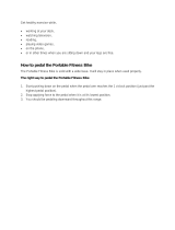
Use this checklist to perform the bike test procedure.
Recheck all the bolts and make sure they are all tightened to the proper torque specification and no parts are missing.
Test the handlebar and seat post to make sure they move freely and you are able to lock in at different positions.
Check the seat to make sure it is level and tight and does not rotate around or tilt. Tighten and adjust as needed.
Test the seat slide for movement front to rear and check it by settings it at different settings.
CAUTION: The flywheel will continue to spin after you pedal and the crank arms and pedals will rotate with the flywheel.
Brake tension is adjustable using the red resistance knob in the front of the bike. Pressing down on the knob will apply the brake if you need to stop
quickly.
Adjust seat post and handlebar post to your needs (Refer to page 16-18). Ride / test the bike for proper operation according to the owner's
manual.
Pedal the bike at a moderate pace and test for proper and smooth resistance changes while varying the amount of turns on the resistance knob.
When the testing is complete tip the bike forward using the handlebars and roll it on a smooth surface to the final location and adjust the
leveling feet so the bike is stable.

"
Your Spinner
®
indoor cycling bike is easy to use. The bike allows the user full control over resistance by simply adjusting the brake pad. Typically,
lower resistance levels enable you to pedal at a faster pace, placing increased demand on the cardiovascular system. Higher resistance levels will
typically deliver a greater muscle/endurance workout at lower RPMs. RPM parameters in the Spinning
®
program range from 60 to 110 RPM.
Additionally, the bike offers seat and handlebar adjustments, allowing the bike to be configured to each users comfort zone.
This section provides the instructions for making seat adjustments, handlebar adjustments, pedal strap adjustments, and for controlling resistance.
Differences between models are noted where applicable.
PLEASE NOTE: In a club setting, we recommend each user to initially be properly fitted on the bike by a certified Spinning® instructor.
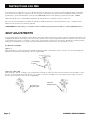
SEAT ADJUSTMENTS
Proper seat height helps ensure maximum exercise efficiency and comfort, while reducing the risk of injury. Adjust the seat height so that the knee joint
is slightly flexed when the extended leg is at the bottom of the pedal stroke. Once the proper height has been achieved, adjust the seat forward or back
so that when the feet are in the 3 o’clock and 9 o’clock positions, the forward knee is directly over the pedal axle. Recheck the seat height again after
making the fore/aft adjustment, as moving the seat forward and backward can have the same effect as moving it higher or lower
To adjust the seat height:
Spinner
®
V
Dismount the bike. Loosen the seat height tension handle by turning the handle counterclockwise. Raise or lower the seat to the desired height, then
tighten the tension handle by turning clockwise. Be sure to tighten firmly.
Spinner
®
Pro / Elite / NXT
Dismount the bike. Turn the seat height pop-pin counterclockwise and pull out on the pin to release it from its current preset location. Raise or lower
the seat to the desired height, then gently release the pop-pin. Raise or lower the seat slightly, if necessary, until the pop-pin engages a preset hole.
Turn the pop-pin clockwise to secure. Be sure to tighten firmly.
V Seat Height
Pop-Pin
Pro / Elite Seat
Height Pop-Pin
NXT Seat
Height Pop-Pin

"
To adjust the seat horizontal position:
Spinner
®
V
Dismount the bike. Loosen the seat fore-and-aft tension handle by turning the handle counterclockwise. Move the seat forward or back to the desired
position, then tighten the tension handle by turning clockwise. Be sure to tighten firmly.
Spinner
®
Pro / Elite / NXT
Dismount the bike. Loosen the seat fore-and-aft tension knob by turning the knob counterclockwise. Move the seat forward or back to the desired
position, then tighten the tension knob by turning clockwise.
Pro / Elite Seat
Fore/Aft Pop-Pin
NXT Seat
Fore/Aft Pop-Pin
V Seat Fore/Aft
Pop-Pin

"!
HANDLEBAR ADJUSTMENTS
Position the handlebar at the same height as your seat, or higher if you feel any discomfort in your back. All Spinner
®
indoor cycling bikes allow for
adjustment of handlebar height. Additionally, the Spinner
®
V allows for fore and aft adjustment of the handlebar.
To adjust the handlebar height:
Spinner
®
V
Loosen the handlebar height tension handle by turning the handle counterclockwise. Raise or lower the handlebar to the desired height, then tighten the
tension handle by turning clockwise. Be sure to tighten firmly.
Spinner
®
Pro / Elite / NXT
Turn the handlebar height pop-pin counterclockwise and pull out on the pin to release it from its current preset location. Raise or lower the handlebar
to the desired height, then gently release the pop-pin. Raise or lower the handlebar slightly, if necessary, until the pop-pin engages a preset hole. Turn
the pop-pin clockwise to secure.
To adjust the handlebar fore / aft for the
Spinner
®
V
:
Loosen the handlebar fore-and-aft tension handle by turning the handle counterclockwise. Move the handlebar forward or back to the desired position,
then tighten the tension handle by turning clockwise. Be sure to tighten the handle firmly.
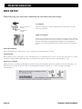
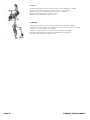
PEDAL STRAP ADJUSTMENT
To adjust the pedal straps:
Place the balls of your feet securely in the toe cages, with the ball of the
foot (or the widest part of your shoe) over the center of the pedals. As
you pedal, concentrate on keeping feet flat, which enables a more
powerful pedal stroke. The front of the shoe may not completely fill the
toe cage.
Note: The pedal straps should be adjusted to hold the foot snugly in the
pedal.
V Handlebar Fore / Aft
Tension Handle
V Handlebar Height
Tension Handle
Pro / Elite
Handlebar Height
Pop-Pin
NXT Handlebar
Height Pop-Pin
Tightening
Clip

#
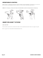
RESISTANCE CONTROL
Pedaling resistance is controlled by the resistance knob. Resistance adjustments can be made while riding to vary the intensity of your workout. To
increase resistance, turn the Push Brake System knob clockwise (+); to decrease resistance, turn the knob counterclockwise (-).
NOTE: In case of emergency, you may press directly down on the Push Brake System knob to bring the flywheel to an abrupt stop.
SMART RELEASE™ SYSTEM
Spinner
®
Elite ONLY
Allows the benefits of the direct drive system with a safety clutch to release the crank from the direct drive when a force is applied to the pedals.
Refer to appropriate section of this manual for Clutch Adjustment Procedures.
V Resistance
Knob
Pro / Elite
Resistance
Knob
NXT
Resistance
Knob
Page is loading ...
Page is loading ...
Page is loading ...
Page is loading ...
Page is loading ...
Page is loading ...
Page is loading ...
Page is loading ...
Page is loading ...
Page is loading ...
-
 1
1
-
 2
2
-
 3
3
-
 4
4
-
 5
5
-
 6
6
-
 7
7
-
 8
8
-
 9
9
-
 10
10
-
 11
11
-
 12
12
-
 13
13
-
 14
14
-
 15
15
-
 16
16
-
 17
17
-
 18
18
-
 19
19
-
 20
20
-
 21
21
-
 22
22
-
 23
23
-
 24
24
-
 25
25
-
 26
26
-
 27
27
-
 28
28
-
 29
29
-
 30
30


Star Trac 7070 Series - Spinner Pro Owner's manual
- Type
- Owner's manual
- This manual is also suitable for
Ask a question and I''ll find the answer in the document
Finding information in a document is now easier with AI
Related papers
-
STAR TRAC FITNESS Spinner NXT 7090 User manual
-
Star Trac 7070 User manual
-
Star Trac 7000 User manual
-
Star Trac Spinner, Spinner Pro, Spinner User manual
-
-
-
-
-
-
Other documents
-
ROOMS TO GO 41433905 Assembly Instructions
-
Martha Stewart Living 680085-C Specification
-
-
 Wakeman M010033 User guide
-
LG F12B4WDL25 Owner's manual
-
-
-
-
Edsal UB700 Operating instructions
-
 Furniture of America CM4230C Installation guide

