Page is loading ...

1
Direct Vent Gas Fireplaces
Model Riviera-42
Canadian Fire Hearth Mfg
7075 Beatty Dr. Mission, B.C. Canada V2V-6C4
Installation and Owner’s Manual
.
.
PLEASE NOTE: This product has been manufactured using
steel and screws. As a result, there are many sharp edges
that can easily cut exposed skin. It is highly recommended
that you wear proper protective gloves while installing the
unit, and during routine cleaning or maintenance.
INSTALLER: Leave this manual with the customer
CUSTOMER: Retain this manual for future reference
©
--Do not store or use gasoline or other
Flammable vapors and liquids in the
vicinity of this or any other appliance.
--WHAT TO DO IF YOU SMELL GAS
• Do not try to light any appliance
• Do not touch any electrical switch; do
Not use any phone in your building;
• Immediately call your gas supplier from a
neighbor’s phone. Follow the gas
supplier’s instructions.
• If you cannot reach your gas supplier, call
The fire department.
-- Installation and service must be performed
By a qualified installer, service agency or
the gas supplier
WARNING: If the information in these
instructions is not followed exactly, a fire or
explosion may result causing property damage,
personal injury or death.
Revision 12.0409

2
Page 1…………………………………………………………………….. .....Cover Page with Safety Information
Page 2………………………………………………………………………….Table of Contents
Page 3 & 4…………………………………………………………………......Customer Greeting & Safety Information
Page 5 ………………………………………………………………………....Features and Specifications
Page 6……………………………………………………………………….....Framing Specifications
Page 7………………………………………………………………………… Placement and Mantel Requirements
Page. 8…………………………………………… …………………………....Corner Installation / Supply Lines Specs.
Page 9………………………………………………………………………….Venting Components
Page 10………………………………………………………………………... Vent Installation
Page 11…………………………………………………………………………Vertical Venting
Page 12…………………………………………………………………………Horizontal Venting
Page 13…………………………………………………………………………Exterior Vent Clearances
Page 14…………………………………………………………………………Installation Planning
Page 15…………………………………………………………………………Installing Non-Combustible Panels
Page 16 & 17…………………………………………………………………...Cleanface Mounting Instruction
Page 18…………………………………………………………………………Glass Door Removal/Re-attachment
Page 19………………………………………………………………………… Electrical
Page 20………………………………………………………………………….Lighting Instructions
Page 21………………………………………………………………………….Final Checks
Page 22………………………………………………………………………….Thermostat / Pilot Check
Page 23………………………………………………………………………….Flame Adjustment
Page 24………………………………………………………………………….Replacement Parts
Page 25………………………………………………………………………….Maintenance
Page 26………………………………………………………………………….Warranty
Table of Contents

3
Date Purchased:_____________________________
Dealer:__________________________________________________________________
Installer:________________________________________________________________
Phone:_________________________________ Serial Number:____________________
CONGRATULATIONS
Welcome to Our Luxor Gas Fireplace Family
We hope you’ve had an easy and enjoyable time choosing from our line of products, and we certainly
appreciate your business. Please take some time to read through the following information, and make
sure to heed all of the warnings. Even though our fireplaces are easy to install and simple to operate,
they are still gas burning units with some inherent dangers if not careful
DO NOT: Use tools to operate controls. Use only your hand to push in and turn controls.
DO NOT: Abuse glass doors by striking or slamming shut.
DO NOT: Clean the appliance when hot.
DO NOT: Use this appliance if you smell gas.
DO NOT: Use this appliance if any part has been under water. Immediately call a qualified service technician to inspect the
appliance and replace any part of the control system and any gas control which has been under water.
General Safety (Home Owner)
•Fire Extinguisher: Every home should have at least on fire extinguisher. An approved Class A-B-C extinguisher should be
mounted on the wall near an exit and close to the application, but not so close that accessibility to the extinguisher could be
blocked by a fire. Your local Fire Department can advise you concerning the most appropriate location.
•Smoke Detectors & Carbon Monoxide Detectors on each floor of your home to ensure your safety. It should be located away
from the gas appliance and close to the sleeping areas. Follow the detector’s manufacturer’s placement installation and
maintenance instructions.
Safety for the installer
Wear gloves and safety glasses for protection.
Exercise extreme caution when using ladders or when
on roof tops.
Be aware of electrical wiring locations in walls and
ceilings.
Use a back support for heavy lifting.
Vent safety
Venting must be installed according to local codes.
Electrical code
When installed, these appliances must be electrically grounded
in accordance with local codes.
FOR YOUR SAFETY – Read before lighting
Installation and repair should be done by a qualified service person. The appliance should be
inspected before use and at least annually by a professional service person. More frequent
cleaning may be required due to excessive lint from carpet, bedding material, etcetera. It is
imperative that control compartments, burners and circulating air passageways of the appliance
be keep clean.

4
This appliance is only for use with the Natural Gas and Propane as indicated on the rating plate.
Note: The copy in the manual is for reference only. In the event of a discrepancy, the label on the unit is to be
taken as the latest version.
GAS SUPPLY
ONLY PERSONS LICENSED TO WORK WITH GAS PIPING MAY MAKE THE NECESSARY GAS CONNECTION TO
THIS APPLIANCE. YOU ARE NOW READY TO HOOK UP THE GAS SUPPLY. BE SURE GAS PLUMBING
INSTRUCTIONS AND ALL PROVINCIAL AND LOCAL CODES ARE CAREFULLY FOLLOWED. USE APPROVED
FLEXIBLE GAS CONNECTIONS OR RIDGID PIPING, DEPENDING ON PROVINCIAL AND LOCAL CODES, TO
ATTACH BURNER TO GAS SUPPLY. BE SURE TO USE PROPER SIZE GAS SUPPLY LINE. CAREFULLY CHECK
ALL CONNECTIONS FOR GAS LEAKS WITH SOAP AND WATER SOLUTION.
EACH INSTALLATION MUST CONFORM TO ALL LOCAL, PROVINCIAL, AND NATIONAL CODES. REFER TO
THE NATIONAL FUEL GAS CODE, LOCAL ZONING AND CODE AUTHORITIES FOR DETAILS ON INSTALLATION
REQUIREMENTS.
WARNING
DO NOT burn ANY materials in this fireplace.
All occupants of the home, especially children, should be alerted about the hazards of the high surface
temperature and the chance of severe burning or the possible ignition of clothing.
Young children should be carefully supervised when they are in the same room as the appliance.
Due to the high temperatures, the fireplace should be installed away from the furniture and draperies and
out of traffic areas.
Nothing should ever be placed on or near the surface of the fireplace, including the top of the unit.
Clothing or other flammable material should not be placed on or near the appliance.
Make certain the control panel, burners, fans, and venting system are kept clean. Inspection of these
systems should be inspected annually by a qualified service technician.
Any safety screen or guard removed for servicing the appliance must be replaced prior to operating the
appliance.
The fireplace, under NO circumstances, should ever be modified.
Do not operate the fireplace if damaged, or if the glass is cracked. Any repairs must be done by a
certified technician.
Certification
The Model Riviera-42 is listed and certified for installation in the U.S.A. and Canada under the
following standards:
ANSI Z21.50/CSA 2.22.
The installation must conform with local codes or, in the absence of local codes, with the National Fuel
Gas and Propane Installation Code, ANSI Z223.1 / NFPA 54 in the US or the Natural Gas and Propane
Installation Code, CSA B149.1 in Canada.
Please contact Canadian Fire Hearth Manufacturing if you have any questions regarding the certification of this appliance.
A Manufactured home (USA only) or mobile home OEM installation must conform with the (U.S.) Manufactured Home
Construction and Safety Standard, Title 24 CFR, Part 3280, or , when such standard is not applicable, the Standard for Fire
Safety Criteria for Manufactured Home Installation Sites and Communities, ANSI/NFPA 501A, in the United States, or the
Mobile Homes Standard, CAN/CSAZ240 MH Series, in Canada

5
FEATURES AND SPECIFICATIONS
Note: Always check appliance label for correct information
MODEL: RIVIERA-42 Natural Gas Propane
Manifold Pressure 3.5in w.c. 10.0in w.c.
Min. Supply pressure 5.0in w.c. 11in w.c
for purpose of input adjustment
Max Supply pressure 11in w.c. 13in w.c.
Orifice size #43 #54
Nominal input rating 23000 BTU/hr Heater Rated
High altitude (US) 0-2000ft / 0-610m
High altitude (Canada) 0-4500ft / 0-1370m
Primary Air Opening
Electrical Rating 115 volts 0.7 amp 60hz
Steady State Efficiency 67.45%
P.4.1 Annual Fireplace Efficiency 56.50%
Circulating fan (optional) Variable Speed
Vent System Direct Vent
Glass Ceramic
Clean Face Kit (required for all installations) Black
Please Note: Only products supplied by the manufacturer may be used in the installation of this appliance.
The Luxor Riviera 42 is a direct vent gas
appliance utilizing an inclined vent for superior
installation flexibility. It enables either horizontal
or vertical vent installation without labouring to
convert over a dual type unit or having to
purchase a dedicated vent configuration.

6
Installation
Note: To provide the easiest installation center the appliance between the vertical framing at the rear so the venting will be
centered. This will allow venting to pass through the framing without modifications.
Minimum Framing Dimensions
Framing the Rear Vent Opening at 14.25” square is necessary for required Wall Thimble. (Part # WTR58) Non-
Combustible panel (supplied by Canadian Fire Hearth) must be installed on the top of the opening.
Non-combustible panel must be
fastened to the top of any
combustible framing.
20.5” from floor or platform to the
frame opening Is lowest acceptable
measurement.
24” to the venting termination
center from either the floor or
exterior ground level is the
Minimum Allowable
Clearance
Clearance to side walls is 0 inches
Rear Venting Exit Minimum. Center vertical
framing with appliance
• Gas Inlet Location
6” from front by 3.5”
above floor.
•Electrical connection is
centered 10” from front at
3.5” from floor on each
side of the appliance
Metal support for Non-
combustible facing
42.5

7
Raised Fireplace Placement
Elevated Height Options
As the Riviera 42 contemporary design leads itself to
installations higher in the wall as would other traditional
appliances. All installations clearance still applies. Non-
combustible panels and distances to combustible materials
must be adhered to. The Clearance to the ceiling must not
be less than the 43” inches dictated by the internal ceiling
height. Mantel sizes and clearance when applicable follow
guideline described in this manual.
Mantel Requirements
No Combustible materials are
permitted lower than 7 ¾” above
the opening of the appliance
represented by the hatch area. A
projection ( mantel or trim) of
combustible material can be no
deeper than 12” from the 7 ¾”
height.
Caution: any finish like stains or
clear coatings must be of a high
heat design to prevent
discolouration.

8
Corner Installation
15.25
68.00
50.49
A 45º angle installation
Installing Gas and Electrical Supply Lines.
Both Gas and Electrical lines must be installed and accessible for the installation of the Riviera 42.
Natural Gas requires a minimum inlet gas pressure of 5.0 in W.C.. Liquid Propane Fuel requires a
minimum of 11.0 in. W.C. IMPORTANT: Installer please allow a portion of the gas line
connecting to the appliance to be flexible enough for moving and aligning the appliance into the
chase. It’s very advisable to connect and secure gas lines before attaching the Cleanface Front.
After securing the Cleanface to the appliance access to the gas compartment becomes limited.
A grounded 117volt AC line must be supplied to the appliance and wired into the electrical box
which is fixed to the right hand side of the appliance. This will supply power to the AC Adapter
which powers the Electronic Valve System. and also provides power for an optional electrical
blower if installed.
Typical venting configuration for
corner installation
Framing and Clearance
Unit maybe installed in any location that maintains proper clearances to air conditioning ducts, electrical
wiring and plumbing. Safety, as well as efficiency of operation must be considered in selecting a fireplace
location. Select a location that does not interfere with room traffic, has adequate ventilation, and offers an
accessible pathway for venting installation.

9
Venting
Venting Parameters.
The Riviera 42 can be installed using either Canadian Firehearth Rigid 5 x 8 co-axial venting or 2-ply
Aluminum Chimney liner that is supplied by Canadian Firehearth. A description of the details and
limitation for venting are listed in this manual. Installer please note; there are variations with venting
configurations specific to either Natural gas or Propane Fuels. The implementation of an intake restrictor
is required in some installation types.
The Riviera 42 requires the mandatory use of Part #WTR58 14 ½ x 14 ½ Wall Thimble in all
installations where vent pipe passes horizontally through any combustible construction.
Venting Components
Installation Considerations
Before installing any venting, proper assessment of venting system must be determined.
Unacceptable vent runs can affect the appliances combustion creating undesirable performance.
WARNING: This gas appliance must not be connected to a chimney flue serving a separate
solid-fuel burning appliance.
Side Wall Co-Axial termination without Nailing Flange V58
Side Wall Co-Axial termination with Nail Flange RVF58
Vertical Co-Axial Termination Simpson DuraVent Part Number 58DVA-VCH
CFH DV Pipe to Duravent Adapter AVT58
Storm Collar 8SC
Wall Thimble 14” WTR58
Rigid Direct Vent Co-Axial Pipe 12” 8RP1
Rigid Direct Vent Co-Axial Pipe 24” 8RP2
Rigid Direct Vent Co-Axial Pipe 36” 8RP3
Rigid Direct Vent Co-Axial Pipe 48” 8RP4
Vent Restrictor ( 3-hole 8” ring) MBR42-3
Adjustable Roof Flashing 1-12 to 7/12 pitch 8AF
Adjustable Roof Flashing 8-12 to 12-12 pitch AFS
Support Plate 8SP
Fire Stop FS58
Rigid Direct Vent Co-Axial Pipe 90º Elbow EL908
Rigid Direct Vent Co-Axial Pipe 45º Elbow EL458
Rigid Direct Vent Co-Axial Pipe 60º Elbow EL608
Rigid Direct Vent Co-Axial Pipe 30º Elbow EL308
Aluminum Flex Direct Vent Co-Axial Pipe 12” FP1
Aluminum Flex Direct Vent Co-Axial Pipe 24” FP2
Aluminum Flex Direct Vent Co-Axial Pipe 36” FP3
Aluminum Flex Direct Vent Co-Axial Pipe 48” PF4
Bulk 2 ply Flex Direct Vent Pipe, 15’ roll B5815
Bulk 2 ply Flex Direct Vent Pipe, 30’ roll B5830
Bulk 2 ply Flex Direct Vent Pipe, 50’ roll B5850

10
Canadian Fire Hearth Rigid Vent System
Vent Installation
• All Rigid vent sections and elbows utilize slip type joints.
• Each joint should be secured by three screws.
• High temperature sealant is recommended at the connection start of the
venting on the appliance end. Use high-temperature silicone or Mill-
Pac©.
• If for any reason the venting must be disassembled upon re-assembly
all vent joints must create a tight fit. If in doubt apply high-temperature
sealant to ill fitting sections.
• Horizontal venting runs will require non-combustible supports such as
metal strapping. Generally every six feet is preferable.
• Co-Axial 2 ply flexible chimney liner must be secured to appliance
with a minimum of three screws for both 5” exhaust and 8” air intake
sections
.• High temperature sealant is recommended at the connection start at
the appliance. Use high temperature silicone or Mill-Pac©.
• It is important to support lengths of flexible chimney liner with non
combustible strapping at three foot intervals to prevent the venting
system from dropping or sagging. Failure to maintain a level or
horizontal rise will lead to improper combustion and can be a
safety hazard.
2 Ply Flexible Chimney Liner supplied by CFH Mfg.
24” minimum
WTR58
Wall Thimble
Non-combustible
Brick
43”
Minimum
18.5”

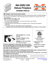
11
Use a roof flashing and
storm collar whenever passing
through the roof
Use a firestop whenever
passing through a ceiling
Use a support box
on exposed vent
36 ft. max.
24 ft.
12 ft.
0 ft
0 ft 20 ft.max
3 hole intake
restrictor for
12 feet or
higher vertical
Special Note for all Rigid Pipe Vent installations
Depending on the configuration starting at the rear of the fireplace either a 60° or 30° elbow will be required to
allow proper alignment of subsequent piping:
*60° required for horizontal direction first
*30° required for vertical direction first
• Up to four elbows (45º or 90º)
may be used
• Elbow combinations can be either
horizontal or vertical in any
combination that does not exceed
the four elbow limit.
• All venting configurations that fall
into the hatch area must have the 3
hole ring intake restrictor.
(See page 12 for detail)
•For all vertical venting a Simpson
Duravent P/N 58VA-VCH
termination is required. When using
CFH rigid venting a ATV58 adapter
is needed.
•Verticle Flexible Chimney
installation must adhere to the same
specifications indicated in the
installation chart. Converting to an
approved rigid vent pipe/ flashing
system is required when passing
through any roof. Approved non-
combustible supports must be
installed. Firestops are required
when passing through floors and
ceiling as dictated by local codes.
Vertical Venting Installations
2 feet maximum horizontal venting
when utilizing zero (0) vertical rise.

12
36 ft. max.
24ft
12 ft
0 ft
20ft max.
36 ft. max.
24ft
12 ft
0 ft
20ft max.
Horizontal Venting Installations
Special Note for all Rigid Pipe Vent installations
Depending on the configuration starting at the rear of the fireplace either a 60° or 30° elbow will be required to allow
proper alignment of subsequent piping:
*60° required for horizontal direction first
*30° required for vertical direction first
• Up to three elbows (45ºor 90º)
may be used.
• Elbow combinations can be either
horizontal or vertical in any
combination that does not exceed
the three elbow limit.
• All configurations in the hatch
area exceeding 12ft. vertical should
have the intake restrictor installed.
• NOTE: LP installations where
the horizontal will exceed 6 feet or
more must have a minimum 4 foot
rise.
• Shortest run for Natural gas is one
foot vertical and one foot horizontal.
Liquid Propane requires two (2)
Feet minimum rise vertical one (1)
foot horizontal.
• Vinyl or Plastic Exterior sidings
or soffit used in close proximity to
the Canadian Fire Hearth
Termination must use the optional
deflector supplied with each
RV58 termination kit
• Flexible Chimney installation must
adhere to the same specifications
indicated in the installation chart.
awing Whfor instWlling restrictor
When Applicable, the MBR42-3 Ring Restrictor is
installed into the intake portion of the Co-Axial venting.
The ring slides into the piping and rest on the rolled bead
manufactured in the pipe.
Note: If the restrictor is required it should be
installed before proceeding with further
connecting of the venting components.
Appliance Rear Vent
Max 2 feet with no vertical rise with
NG. A ratio of 2 horizontal feet for
every one foot vertical is the
optimum vent ratio.

13
Letter
CDN Installation
US Installation
Description
A
30cm 12”
Clearance above grade, verandah, porch, deck, or balcony.
B
30cm
9”
Clearance from window or door that may be opened.
C
38cm* 15”*
Clearance from permanently closed window (to prevent condensation)
D
56cm 22”
Vertical clearance to ventilated soffit located above the terminated
within a horizontal distance of 2 feet (60cm) from the center line of
terminal.
E
56cm* 22”*
Clearance to unventilated soffit.
F
38cm* 15”*
Clearance to outside corner.
G
38cm* 15”*
Clearance to inside corner.
H
91cm within a height of
4.5m above the
meter/regulator
assembly
3’ within a height of 15’
above the meter/regulator
assembly.*
Clearance to each side of center line extended above meter/regulator
assembly.
I
91cm
3’*
Radial clearance around service regulator vent outlet.
J
30cm
9”
Clearance to non-mechanical air supply inlet to building, or the
combustion air inlet to any other appliance.
K
1.83m
3’ above if within 10’
horizontally.
Clearance to mechanical air supply inlet.
L
2.13mt
7’*t
Clearance above paved sidewalk or paved driveway located on public
property.
M
56cm +
22” +
Clearance under verandah, porch, deck, or balcony.
1 In accordance with the current CSA B149.1, Natural Gas and Propane Installation Code.
2 In accordance with the current ANSI 2223.1 NFPA 54, National Fuel Gas Code.
* These Numbers are only estimates. Clearances are in accordance with local installation codes and the requirements
of the gas supplier.
t A vent shall not terminate directly above a sidewalk or paved driveway that is located between two single family
dwellings and it serves both dwellings.
+ Permitted only if verandah, porch, deck, or balcony is fully open on a minimum of two sides beneath the floor.
NOTE: Venting terminals shall not be recessed into walls or siding.
Minimum Vent Termination Clearances

14
The recommended order of installation is as follows:
1 – Familiarize yourself with this manual.
2 – Check the minimum installation dimensions and vent installation.
3 – Check your local installation codes.
4 – Check you have the parts and components necessary to complete the installation.
5 – Check the gas and electrical supplies are ready.
6 – Prepare opening (remove any loose materials)
7 – Install Venting
8 – Install base unit and connect vent
9 – Connect gas and electrical supplies.
10 – Install operational components and prepared for first test fire
11 – Check to verify adequate accessibility clearance for service & proper operation
12 – Check operation of unit
13 – Take time to explain operation to customer (most call backs are caused by the customer not understanding the operation
of the unit.)
Existing Gas Supply
Before interrupting the existing gas supply it is recommended that the following be checked.
Shut down all gas appliances and carry out a pressure test to ensure there are no leaks in the system.
Before connecting the appliance to the gas supply line, double check that the appliance you have purchased is designed for the
gas type you are using. The gas type markings are located on the certification label and also on the appliance’s gas valve.
Check the gas pressure immediately upstream to ensure you will be able to supply the minimum inlet pressure for the
appliance.
Check your pipe sizing to ensure sufficient volume will be supplied to the appliance.
Gas Supply Installation
Provide adequate clearance for the proper installation and checking of the gas connection.
Have your gas supplier or a qualified gas fitter run a gas supply line into the gas fireplace. The line must be properly sized
and fitted according to the installation codes. Upstream of the appliance supply connection, the fitter shall provide an easily
accessible manual shut-off valve.
The gas supply pipe should enter the appliance case through the opening at the right side. The supply pipe should be
connected to the appliance gas inlet pipe situated at the right side of the control unit. Supply line connection to the inlet pipe
is 3/8 NPT.
Use only new black iron or steel pipes or copper tubing if acceptable – check local codes.
Note that in the USA copper tubing must be internally tinned for protection against sulfur compounds.
Unions in gas should be of ground joint type. Sealant used must be resistant to the action of all gas constituents including LP
gas. Sealant should be applied lightly to male threads to ensure excess sealant does not enter gas lines.
Pressure testing the supply line for leaks
The appliance and its individual shut-off valve must be disconnected from the gas supply piping system during any pressure
testing of the system at test pressures in excess of ½ psig (3.4kPa). The appliance must be isolated from the gas supply piping
system by closing its individual manual shut-off valve during any pressure testing of the gas supply piping system at test
pressures equal to or less than ½ psig (3.5kPa). Failure to do so will damage the appliance’s gas valve. Such damage is not
covered by the manufacturer’s warranty.
When testing for leaks:
Make sure that the appliance is turned off.
Open the manual shut-off valve.
Test for leaks by applying a liquid detergent or soap solution to all ball joints. Bubbles forming indicate a gas leak.
Correct any leak detected immediately.
Never use an open flame to check for leaks.
The pressure test point locations are built in to the regulator that controls the burner manifold pressure. The correct pressure
range is shown in the table in the specification section of this manual. The pressure check should be made with the burner lit.
See lighting instruction section for full operating details.
Installation Planning

15
The Riviera 42 is shipped with five (5) separate panels of non-combustible panels which must be
installed with the appliance to conform with to certified safety standards. Two of the panels are
secured to the Cleanface from at the factory and require no special attention and are mentioned
only to avoid confusion. The large 42”x34.25” inch front panel utilizes the cutout for installation
under the appliance. The 14 ½ x 3 ½ must be installed at the top of the wall opening when
venting is routed horizontally from the rear of the appliance.
Placing and Securing Non-Combustible Panels
Cleanface Surround
Non-combustible front panel
Plate for horizontal
Venting through
combustible wall
Cut out from front panel must
be placed under appliance
before installation
Metal panel brace

16
Attaching the Cleanface Mounting Frame before Installation.
As noted previously, Gas and Electrical lines should be hooked to the appliance before attaching
Cleanface Surround and fitting Non-combustible front.
The Cleanface Front Assembly is fastened to the front of the Firebox unit by the self-tapping
sheet metal screws. (Fig 1)Before beginning take care to push up the left and right tabs for
supporting the cover grille to be installed on completion.
A Power drill with ¼ Hex Nut driver should be used to attach surround as shown in Figure 2. Pre-
punched holes are provided. Once the top has been secured locate the two pre-punched holes
located on the lower inside faces. Secure the sides to the appliance with tapping screws (Figure 3)
Next, secure the supplied metal wallboard brace onto the vertical framing on either side. The
brace height should be set so that it will adequately support the Non-combustible panel and the
drywall upon completion.
Figure 1
Figure 2
Figure 3
Figure 4

17
The brace should be fastened by either or screws to secure it in place. The Non-combustible
board can be fastened with standard drywall screws through the recessed holes provided when the
appliance is ready to close in
Figure 5
Figure 6
Install metal brace at 36” from bottom
of floor or base of elevation

18
Step#2 Releasing Door Latch
Step #3 Lifting the Glass Door Assembly
from Locator Tab
1) Remove the Control Valve Compartment cover grille which provides access to the door latch
mechanism
2) Door latch mechanisms located on the lower edge of the glass door are pulled forward then moved
down. The latch is spring loaded so sufficient effort is required to clear it from the door frame
before it will release.
3) Holding the bottom edge of the door frame tilt out the door assembly 4-5” then lift up to slide the
frame off the two retaining tabs located at the top of the Fire Box Enclosure
WARNING: Do not abuse the appliance’s glass by striking, slamming or similar trauma. Do not use the
appliance with the door removed, glass panel cracked or broken. Only use OEM door assembly designed for
use with this appliance. Do not use substitute materials. Replacement of the panel should only be carried out by
a licensed qualified service person
Door Removal and Re-Installation Instructions
Window Re-Installation
To Re-install the Glass Door Assembly it is simply a reversal of the removal procedure. Hold the Door assembly at
about a 45° angle and line up the two top slots located on the frame top edge onto the two retaining tabs (shown in
illustration). Once in the grooves, the door should simply close down into place. If the assembly is not aligned well
some adjustment to the left or the right may be required to permit proper closure. DO NOT FORCE ASSEMBLY!
When Door assembly is aligned pull latch mechanism forward and up to secure door. Replace the Valve Compartment
Grille
Picture of cover grille here
NOTE: In the event of glass fracture or other related damage the Glass door must be replaced as a
complete assembly. The Robax Glazing/Frame Assembly must be provided bt Canadian Fire
Hearth Mfg.only. Part #RGD42RIV.
grille

19
Electrical Diagram
This appliance is equipped with a three pronged (grounding) plug for your protection against
shock hazard and should be plugged directly into a properly grounded three prong
receptacle. Do not cut or remove the grounding prong from this plug
Resistor Adjustable
Thermal disk (close on rise)
Fan Motor
G
L1(BK)
L2 (W)
Electrical Schematic
This appliance, when installed, must be
electrically grounded in accordance with
local codes or, in the absence of local
codes, with the National Electrical Code,
ANSI/NFPA 70, or the Canadian
Electrical Code, CSA C22.1.
CAUTION: Label all wires
prior to disconnection when
servicing controls.
Wiring errors can cause
improper and dangerous
operation.
VERIFY PROPER OPERATION
AFTER SERVICING
Optional Fan Kit
Each kit contains:
-Fan assembly with mounting
gasket
-Grounded electrical harness
-Rheostat & thermal switch
fan kit p/n FK-SG

20
For your safety, read the following before lighting:
1. STOP! Read the safety information above on
this label.
2. Set the thermostat to lowest setting or switch
to off
3. Turn off all electrical power to the appliance.
4. This appliance is equipped with an ignition
device which automatically lights the pilot.
Do not try to light the pilot by hand.
5. Remove control access cover
6. Identify that the module control switches are
set to the desired operation. Check if the
electronic module is powered by back up
batteries and/or AC adapter. The back up
batteries will light the appliance even if the
AC power has been turned off.
7. Wait five minutes to clear out any gas. Then
smell for gas, including near the floor. If you
smell gas, STOP! Follow “B” in the safety
information on this label. If you don’t smell gas
go on to the next step.
8. Turn up thermostat or turn on power switch –
sufficient time must be allowed for air to escape
from lines if the unit is being lit for the first
time.
9. Replace control access cover.
10. Turn on all electric power to the appliance.
11. Set thermostat to desired setting.
12. If the appliance will not operate, follow the
instructions “To Turn Off Gas To Appliance”
and call your service technician or gas supplier.
1. Set the thermostat to lowest setting or
on/off switch to off.
2. Turn off all electrical power to the
appliance
3. Remove control access.
4. Remove backup batteries if service is to be
performed or for extended shutdown.
5. Replace control access.
Lighting Instructions
Operating Instructions
WARNING: If you do not follow these instructions exactly, a fire or explosion may result causing property damage
and personal injury or death
A. This appliance is equipped with an ignition device which
Automatically lights the pilot. Do Not try to light the pilot
by hand.
B. BEFORE LIGHTING smell all around the appliance area
For gas. Be sure to small next to the floor because some
gas is heavier than air and will settle on the floor.
WHAT TO DO IF YOU SMAELL GAS – Do not try to
Light the appliance – Do not touch any electric switch; do
not. Use any phone in your building – Immediately call your
gas supplier from a neighbour’s phone. Follow the gas
supplier’s instructions. – If you cannot reach your gas supplier,
call the fire department
C. Use only your hand to push in or turn control knob.
Never use tools. If the knob will not push in or turn
by hand don’t try to repair it, call a qualified service
technician. Force or attempt repair may result in a
fire or explosion.
D. Do not use this appliance if any part has been under
Water. Immediately call a qualified service
technician. To inspect the appliance and replace any
part which has been under water.
To Turn Off Gas to Appliance
/