Page is loading ...

INSTRUCTION MANUAL
• Read this Instruction Manual before using the product.
• Read the safety notes carefully.
• Keep this Instruction Manual in a safe and convenient place for future reference.
SM-P00104-A
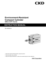
Silencer Outdoor
SL-□-W Series

SM-P00104-A PREFACE
i 2022-01-24
PREFACE
Thank you for purchasing CKD's "SL-□-W Series " silencer outdoor series.
This Instruction Manual contains basic matters such as installation and usage instructions in order to
ensure optimal performance of the product. Please read this Instruction Manual thoroughly and use the
product properly.
Keep this Instruction Manual in a safe place and be careful not to lose it.
Product specifications and appearances presented in this Instruction Manual are subject to change
without notice.
• The product is intended for users who have basic knowledge about materials, piping, electricity,
and mechanisms of pneumatic components. CKD shall not be responsible for accidents caused
by persons who selected or used the product without knowledge or sufficient training.
• Since there are a wide variety of customer applications, it is impossible for CKD to be aware of all
of them. Depending on the application or usage, the product may not be able to exercise its full
performance or an accident may occur due to fluid, piping, or other conditions. It is the
responsibility of the customer to check the produ
ct specifications and decide how the product shall
be used in accordance with the application and usage.

SM-P00104-A SAFETY INFORMATION
ii 2022-01-24
SAFETY INFORMATION
When designing and manufacturing any device incorporating the product, the manufacturer has an
obligation to ensure that the device is safe. To that end, make sure that the safety of the machine
mechanism of the device, the pneumatic control circuit, and the electric system that controls such
mechanism is ensured.
To ensure the safety of device design and control, observe organization standards, relevant laws and
regulations, which include the following:
ISO 4414 and JIS B 8370 (the latest edition of each standard)
In order to use our products safely, it is important to select, use, handle, and maintain the products
properly.
Observe the warnings and precautions described in this Instruction Manual to ensure device safety.
Although various safety measures have been adopted in the product, customer's improper handling
may lead to an accident. To avoid this:
Thoroughly read and understand this Instruction Manual
before using the product.
To explicitly indicate the severity and likelihood of a potential harm or damage, precautions are
classified into three categories: "DANGER", "WARNING", and "CAUTION".
DANGER Indicates an imminent hazard. Improper handling will cause death or
serious injury to people.
WARNING
Indicates a potential hazard. Improper handling may cause death or serious
injury to people.
CAUTION Indicates a potential hazard. Improper handling may cause injury to people
or damage to property.
Precautions classified as "CAUTION" may still lead to serious results depending on the situation.
All precautions are equally important and must be observed.
Other general precautions and tips on using the product are indicated by the following icon.
Indicates general precautions and tips on using the product.

SM-P00104-A SAFETY INFORMATION
iii 2022-01-24
Precautions on Product Use
WARNING
The product must be handled by a qualified person who has extensive knowledge and
experience.
The product is designed and manufactured as a device or part for general industrial machinery.
Use the product within the specifications.
The product must not be used beyond its specifications. Also, the product must not be modified
and additional work on the product must not be performed.
The product is intended for use in devices or parts for general industrial machinery. It is not
intended for use outdoors (Except for outdoor specification products) or in the conditions or
environment listed below.
• In applications for nuclear power, railroad system, aviation, ship, vehicle, medical equipment,
and equipment that directly touches beverage or food.
• For special applications that require safety including amusement equipment, emergency shut-
off circuit, press machine, brake circuit, and safety measures.
• For applications where life or properties may be adversely affected, and special safety
measures are required.
(Exception is made if the customer consults with CKD prior to use and understands the
specifications of the product. However, even in that case, safety measures must be taken to
avoid danger in case of a possible failure.)
Do not handle the product or remove pipes and devices until confirming safety.
• Inspect and service the machine and devices after confirming the safety of the entire system.
Also, turn off the energy source (air supply or water supply) and power to the relevant facility.
Release compressed air and fluid from the system and use extreme care to avoid water or
electric leakage.
• Since there may be hot or live parts even after operation has stopped, use extreme care when
handling the product or removing pipes and devices.
• When starting or restarting a machine or device that incorporates pneumatic components,
make sure that a safety measure (such as a pop-out prevention mechanism) is in place and
system safety is secured.

SM-P00104-A SAFETY INFORMATION
iv 2022-01-24
Precautions on Product Disposal
CAUTION
The product's working material uses metal or resin parts.
After disassembling according to "4.3 Disassembly and assembly method", please dispose
of separately.
(Refer to "1.4 Internal Structure Diagram" for the
material.)

SM-P00104-A CONTENTS
v 2022-01-24
CONTENTS
PREFACE ........................................................................................................................... i
SAFETY INFORMATION .................................................................................................. ii
Precautions on Product Use .......................................................................................... iii
Precautions on Product Disposal .................................................................................. iv
CONTENTS ....................................................................................................................... v
1. PRODUCT OVERVIEW ............................................................................................. 1
1.1 Model Number Indication .................................................................................... 1
1.2 Specifications ...................................................................................................... 1
1.2.1 Product specifications .................................................................................... 1
1.3 Dimensions ......................................................................................................... 2
1.3.1 Discrete .......................................................................................................... 2
1.3.2 Components ................................................................................................... 2
1.4 Internal Structure ................................................................................................ 3
2. INSTALLATION ......................................................................................................... 4
2.1 Environment ........................................................................................................ 4
2.2 Unpacking ........................................................................................................... 4
2.3 Mounting ............................................................................................................. 4
3. USAGE ....................................................................................................................... 5
3.1 Safety Instructions .............................................................................................. 5
4. MAINTENANCE AND INSPECTION ......................................................................... 6
4.1 Daily Inspection ................................................................................................... 6
4.2 Periodic Inspection.............................................................................................. 6
4.3 Disassembly and assembly method ................................................................... 7
4.3.1 Disassembly ................................................................................................... 7
4.3.2 assembly method ........................................................................................... 7
5. TROUBLESHOOTING............................................................................................... 8
5.1 Problems, Causes, and Solutions ...................................................................... 8
6. WARRANTY PROVISIONS ....................................................................................... 9
6.1 Warranty Conditions ........................................................................................... 9
6.2 Warranty Period .................................................................................................. 9
P

SM-P00104-A 1. PRODUCT OVERVIEW
1 2022-01-24
1. PRODUCT OVERVIEW
1.1 Model Number Indication
(a)
(a) Port size
8A Rc1/4
10A
Rc3/8
15A
Rc1/2
1.2 Specifications
1.2.1 Product specifications
Model no.
Descriptions
SL-8A-W SL-10A-W SL-15A-W
Working fluid
Compressed air
Max. working pressure
MPa
0.9
Min. working pressure
MPa
0
Proof pressure
MPa
1.35
Fluid temperature
°C
5 to 60
Ambient temperature
°C
-10 to 60 (no freezing)
Port size
Rc1/4 Rc3/8 Rc1/2
Weight
g
75 100 105
Applicable cylinder tube bore size
mm
Ø50 to ø100 Ø63 to ø140 Ø75 to ø180
N
oise reduction
effect
dB[A]
20 or more
Flow rate Note 1 ㎥/min (ANR)
2.4 3.2 4.1
Effective cross
-
sectional area
mm
2
36 48 61
Note 1: This is the flow rate at pressure of 0.5 MPa.
SL 8A
W

SM-P00104-A 1. PRODUCT OVERVIEW
2 2022-01-24
1.3 Dimensions
1.3.1 Discrete
Model
no.
P
ort
size
A
B
φC
D
SL-8A-W R1/4 64
41 30 17
SL-10A-W R3/8 74.5
49.5
36 24
SL-15A-W R1/2 77.5
49.5
36 24
1.3.2 Components
Replacement element
Part name Model no.
Replacement element SL-□A-EL
Port
size

SM-P00104-A 1. PRODUCT OVERVIEW
3 2022-01-24
1.4 Internal Structure
JIS symbol
No. Part name Material
1
C
snap ring
Stainless steel
2
Perforated metal
Stainless steel
3
Wire mesh
Stainless steel
4
Element
Vinylidene chloride
5
Body
Aluminum

SM-P00104-A 2. INSTALLATION
4 2022-01-24
2. INSTALLATION
2.1 Environment
Do not use the product in an environment where:
• Ambient temperature When the product temperature exceeds the range of -10 to +60 ℃.
(If used in an environment exposed to direct sunlight, the product temperature may become higher
than the ambient temperature.)
• Air freezes
• If there is a corrosive gas, liquid or chemical atmosphere
• Dusty atmosphere
• If there is a heat source in the surroundings, try to avoid radiant heat
• Ozone generation environment
2.2 Unpacking
• Check that the model number ordered and the model number indicated on the product are the same.
• Check the exterior of the product for any damage.
2.3 Mounting
CAUTION
Follow the recommended torque.
It may cause loosening of screws, air leakage and damage.
Pay attention to the conditions of use.
Do not apply a lateral load to the main body during or after mounting.
Install the silencer so that the exhaust air does not come into direct contact with your eyes.
Make sure there is enough space around the silencer for installation and removal.
• For the lock nut recommended tightening torque, refer to the table below. Be careful not to damage
the nut by over-tightening it.
Lock nut recommended tightening torque
Screw size
Tightening torque (N·m)
R1/4
6~8
R3/8
13~15
R1/2
16~18
Do not install the exhaust port of the silencer facing up.
Take measures to prevent dust, dirt and rainwater from entering through the exhaust port.

SM-P00104-A 3. USAGE
5 2022-01-24
3. USAGE
3.1 Safety Instructions
WARNING
Use the product within the specifications.
Control the speed by gradually turning the needle from the fully closed position.
Turning the needle counterclockwise will lift the needle to an open position.
CAUTION
The product is designed for compressed air.
Do not use other fluids.
The exhaust port may become blocked due to clogging of the silencer.
Consider a safety design that will prevent the entire system from malfunctioning.
The muffling effect value is based on the JIS standard.
The muffling effect may change depending on the circuit and pressure used
.

SM-P00104-A 4. MAINTENANCE AND INSPECTION
6 2022-01-24
4. MAINTENANCE AND INSPECTION
WARNING
Use a special tool to remove and assemble the C-shaped retaining ring and be careful not to
fly the C-shaped retaining ring.
When replacing the element, be sure to assemble the C-shaped retaining ring.
If the assembly is incomplete, the internal components may pop out during use and it is
dangerous.
CAUTION
When replacing the element, be sure to assemble the wire mesh and punching metal.
Store in a hot and humid place or in a place below 40 ° C away from direct sunlight.
4.1 Daily Inspection
• Thoroughly read and understand this Instruction Manual before maintenance and inspection.
• Check that the product operates properly before starting use.
4.2 Periodic Inspection
• In order to use the product under optimum conditions, perform a periodic inspection every six
months.
• It is recommended to check that there is no leakage from the pipes.

SM-P00104-A 4. MAINTENANCE AND INSPECTION
7 2022-01-24
5 C-shaped retaining
ring with the edge
facing up
4.3 Disassembly and assembly method
4.3.1 Disassembly
Parts such as elements can be taken out by removing the C-shaped retaining ring of the exhaust port
with a special tool.
4.3.2 assembly method
If clogging occurs, replace the element.
Element replacement procedure
1 Remove the C-shaped retaining ring with a
special tool.
(At this time, be careful not to let the C-shaped
retaining ring pop out.)
2 Take out the punching metal and wire mesh.
3 Remove the old element.
4 Make sure there is a wire mesh inside the
silencer and insert a new element.
5 Assemble the wire mesh, punching metal, and C-
pshaped retaining ring in this order.
(At this time, pay attention to the direction of the C-shaped retaining ring
Depending on the usage conditions of the silencer, the element may be clogged and the
exhaust flow rate may decrease.
This product is guaranteed for outdoor use, but it does not guarantee corrosion resistance (no
rust, no discoloration).
Wire mesh
Element
punching metal
C-shaped retaining ring
One piece like a roll
Wire mesh
Element
punching metal
C-shaped retaining ring

SM-P00104-A 5. TROUBLESHOOTING
8 2022-01-24
5. TROUBLESHOOTING
5.1 Problems, Causes, and Solutions
If the product does not operate as intended, check the table below for a possible solution.
Problem Cause Solution
The speed of the device has
slowed down.
Decrease in exhaust flow rate due to
element clogging.
Replace the element with a new one.
Internal parts such as
elements have popped out
Insufficient assembly of C-shaped retaining
ring when replacing the element
.
Assemble so that the groove C-shaped retaining
ring of the silencer body fits securely.
If you have any other questions or concerns, contact your nearest CKD sales office or distributor.

SM-P00104-A 6. WARRANTY PROVISIONS
9 2022-01-24
6. WARRANTY PROVISIONS
6.1 Warranty Conditions
Warranty coverage
If the product specified herein fails for reasons attributable to CKD within the warranty period specified
below, CKD will promptly provide a replacement for the faulty product or a part thereof or repair the
faulty product at one of CKD’s facilities free of charge.
However, following failures are excluded from this warranty:
• Failure caused by handling or use of the product under conditions and in environments not
conforming to those stated in the catalog, the Specifications, or this Instruction Manual.
• Failure caused by incorrect use such as careless handling or improper management.
• Failure not caused by the product.
• Failure caused by use not intended for the product.
• Failure caused by modifications/alterations or repairs not carried out by CKD.
• Failure that could have been avoided if the customer’s machinery or device, into which the product is
incorporated, had functions and structures generally provided in the industry.
• Failure caused by reasons unforeseen at the level of technology available at the time of delivery.
• Failure caused by acts of nature and disasters beyond control of CKD.
The warranty stated herein covers only the delivered product itself. Any loss or damage induced by
failure of the delivered product is excluded from this warranty.
Confirmation of product compatibility
It is the responsibility of the customer to confirm compatibility of the product with any system,
machinery, or device used by the customer.
Others
The terms and conditions of this warranty stipulate basic matters.
When the terms and conditions of the warranty described in individual specification drawings or the
Specifications are different from those of this warranty, the specification drawings or the Specifications
shall have a higher priority.
6.2 Warranty Period
The product is warranted for one (1) year from the date of delivery to the location specified by the
customer.
/