Rose Lighting TC809 User manual

Type
User manual

Rose Lighting TC809 is an Art-Net controller that converts Art-Net signals into various pixel lamp chip signals. It features 8 output ports, supports automatic addressing, and is compatible with a wide range of LED driver chips. With a user-friendly LCD display, it allows for easy configuration and monitoring of the controller's status. The TC809 can be used as a standalone unit or cascaded with other controllers for larger installations.

Rose Lighting TC809 is an Art-Net controller that converts Art-Net signals into various pixel lamp chip signals. It features 8 output ports, supports automatic addressing, and is compatible with a wide range of LED driver chips. With a user-friendly LCD display, it allows for easy configuration and monitoring of the controller's status. The TC809 can be used as a standalone unit or cascaded with other controllers for larger installations.

1 / 17
TC809 Art-Net Controller User Manual
Please read this manual carefully before installing and using this product
1. Product introduction
This TC-809 controller is a controller with LCD digital interface display, which converts Art-Net signals into
various pixel lamp chip signals. It adopts standard Ethernet transmission and additionally accepts DMX512 signal
control. Eight output ports, can control a variety of LED driver chips, support automatic addressing function,
convenient for users to access different types of lamps, and realize unified control of different lamps in the project.
The input network port can be directly connected to the computer network card, and can also be connected to the
computer network card via a switch or photoelectric converter. Widely used in buildings, municipal lighting, stage
scenery, entertainment venue decoration, etc.; it can achieve various running changes such as horse racing,
running water, trailing, coloring, scanning, raindrops, etc., and has the advantages of convenient wiring and simple
use; Single unit can be used in cascade connection.
2. Dimensions & Technical Parameters
TC809 Art-Net Controller Dimensions
2 / 17
Technical Parameters
Name Description & Parameters
Operating Voltage DC5-24V
Input Signal Art-Net / DMX512
Output Signal DMX512 / SPI (TTL)
Refresh Rate 30(ms)
Control Pixels RGB 1020pixels*8Ports / RGBW 765pixels*8Ports MAX
Cascades QTY 170pixels*8Port / 128pcs 340pixels*8Port / 64pcs
510pixels*8Port / 42pcs 680pixels*8Port / 32pcs
850pixels*8Port / 25pcs 1020pixels*8Port / 21pcs
Operating temperature -20 ~55
Protection level IP20
Accessories 8G Memory Card * 1 / 3P terminal * 8 / 2P terminal * 1
Dimensions L212 x W138 x H30 mm
Packing Size 25 x16.5 x4 cm
Product weight 0.73 kg
3. Functions and features
3.1 Provide LCD screen display, which can display the model, ID, and working status of the controller.
3.2 Have 8 ports output, each port can Control to 170/340/510/680/850/1020 pixels (depending on the
number of different loaded chips).
3.3 The port outputs two signal protocols: ①DMX512/1990 internaonal standard protocol and DMX512
extended protocol (RS-485 differenal signal); ②TTL serial protocol (level signal).
3 / 17
3.4 Support a variety of pixel control ICs, flexible control methods.
3.5 Controller network IP online/manual setting function.
3.6 With DMX512 write address function, single port or all ports load DMX512 IC write address.
3.7 It can be directly connected to the computer network card when online, or it can be connected
to the computer network card via a switch or photoelectric converter.
3.8 It can be used as a single unit, or multiple units can be cascaded to use,
supporting multiple connections of switches.
3.9 Support DMX512, online and offline integrated control, online priority is the highest, automatically
switch to offline playback when there is no 2 online and DMX51 signal, online can be connected to
MADRIX, offline can be connected to DMX512 console.
3.10 The SD card stores offline effect files and supports the download of effect files through Art-Net
network, no need to insert or pull out the SD card.
3.11 It can be used as the main control (with SD card inserted) or as a sub-controller (without SD card)
when it is online.
3.12 The sub-control cascade can be interchanged at will, and it has strong adaptability to lighting engineering.
3.13 The communication adopts the international standard TCP/IP network protocol, the optional
transmission rate supports 100M/Gigabit adaptive, the transmission speed is more stable and fast, and
the nominal transmission distance between each two controllers can reach 100 meters.
3.14 The network interface with indicator light is adopted, and the T568B line sequence protocol is adopted.
3.15 Port ESD protection design.
3.16 Power input interface reverse connection protection design.
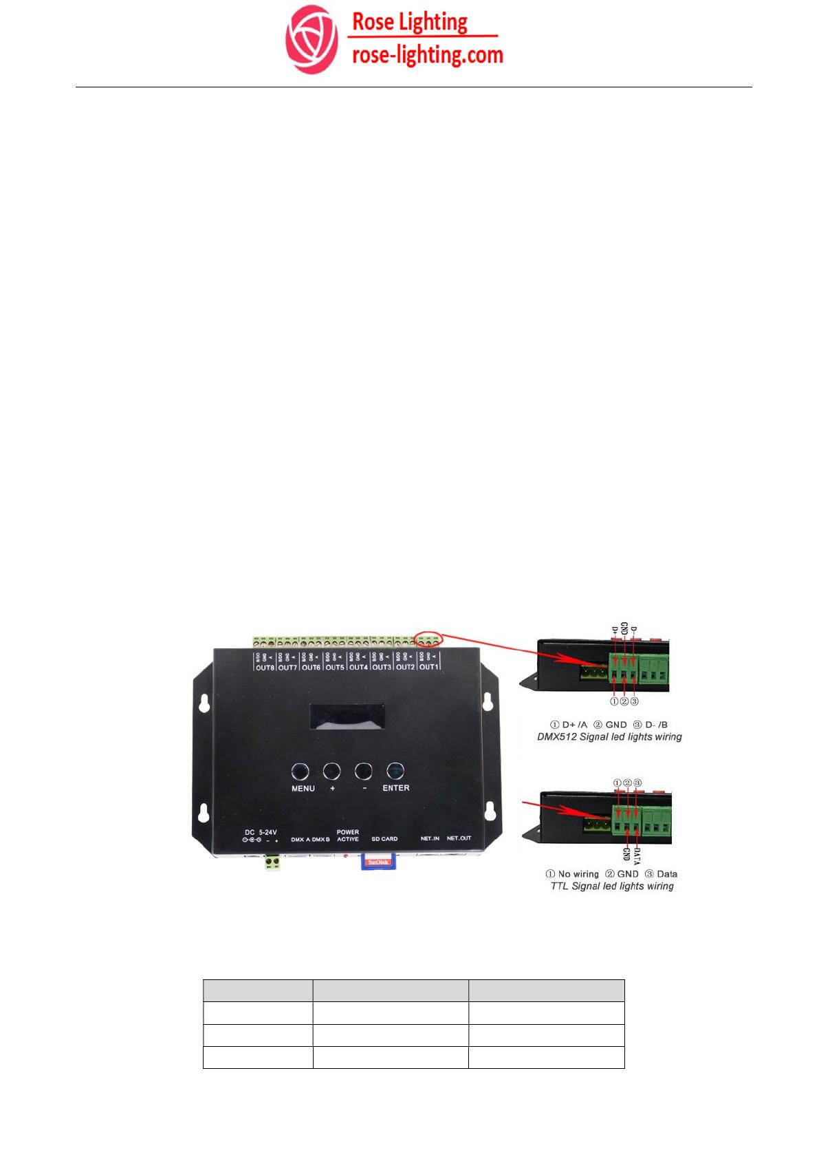
4. LED Lights Wiring Instructions
When outputting DMX512/HDMX/TM512/UCS512/SM16512 control signals (differential), 3-wires are required.
When outputting control signals (TTL) such as WS2811/UCS1912/UCS1903/GS8206, 2-wires are required.
LED Lights Wiring Definition
3P Terminal DMX512 Signal TTL Signal
A D+ (NULL)
GND GND GND
B/DO D- DATA
4 / 17
5. Control IC Type
IC Type IC Model NO. Color
2811 TM1804, TM1809, TM1812, UCS1903, UCS1909, UCS1912, UCS2903, UCS2909, UCS2912,
UCS2919, WS2811, WS2812, GS8206, SM16703 …… RGB
1914 TM1914…… RGB
5603 UCS5603….. RGB
512 DMX512, HDMX, TM512, UCS512, SM16512…… RGB
2904 UCS2904B…… RGBW
6. Set the IP address of the computer network card
Correctly select the network card connected to the controller and set the corresponding IP address for it.
Selection (TPC/IPv4)-Properties- Manually set the IP address information
IP address: 192.168.1.X (Unoccupied IP address)
Subnet mask: 255.255.255.0
Default gateway: 192.168.1.1
This step is very important !!!
It may cause the software to fail to search the controller correctly.
7. Art-Net Setting Software- LEDForShow
7.1 LEDForShow Software interface introduction
5 / 17
1- Select Network Card
2- Controller parameter setting module
3- DMX512 online address code, controller parameter sending, controller search
4- Controller port test module
5- MADRIX effect recording module
6- Lighting layout conversion module
7.2 Open the controller setting software
6 / 17
7.2.1 Select Network > Select the network card connected to the controller
7.2.2 Click the "Search Controller" button on the right, and when the controller is searched, you can set the
parameters of the controller.
7.3 Controller parameter setting
Name Description Remark
IP Set a fixed IP address for the controller,
Set to 192.168.1.X (Unoccupied IP address) On the same network segment as the computer
Mask Set to 255.255.255.0 The same as the computer settings
Number of Controller Number of connectable sub-controllers Set according to project usage
Start Universe Virtual space in the first output port MADRIX
software
IP Protocol Loaded IC model for port output The same as the loaded IC signal protocol on the
connected Lights
Number of Pixels Set the MAX loading pixels of the controller port ;
170pixels/1U Max 1020pixels/U
DMX512 MAX 510pixels/3U
SPI/TTL MAX 1020pixels/6U
Used Ports Use 4 Ports / Use 8 Ports When set to "Use 4 Ports", there is no signal
output from the "5-8" ports of each controller
Double-click the corresponding number box, after the number is selected, you can change it as needed, and
set the controller's IP address, sub-control number, starting space, etc.
The controller connected to the network card in the cascade mode will only display the IP address of the first
controller, and only need to set the corresponding number of sub-control cascades.
Note: The above is the grouping of the controller to the switch. When the controller is directly connected to
the computer, only one IP address will appear.
7 / 17
Click the " IP Protocol " box arrow to pop up a drop-down menu to select the LED lights chip.
Click the " Number of Pixels " box arrow to pop up a drop-down menu to select port loading.
Click the " Used Ports " box arrow to pop up a drop-down menu to select the port mode,
and you can choose "4" or "8" output.
When the controller is connected to the LAN and conflicts with the MAC address of other devices in the LAN, click
the number in the "New MAC" box. After the number is selected, you can change it as needed.
After setting each parameter, click "Send to Controller" to save the parameters to the controller.
7.4 IP address and controller arrangement
8 / 17
Note: When using multiple controllers in series, after setting the IP address using LEDForShow software,
the controller identification method is: IP+ID, such as 192.168.1.10: ID001, and the following controllers are
automatically arranged as 192.168.1.10: ID002, 192.168 .1.10: ID003......
8. DMX Address Code Online & Controller Test
8.1 Set and store the controller parameters, and then correctly connect the DMX512 lamp signal to the
controller. Fill in the value of "Used Channels" and "Start Channels" in the LEDforShow software, and click
"Encoding Address" to write the address code for DMX512 Lights.
9 / 17
8.2 Controller test method:
1> Fill in the IP address of the corresponding controller
2>Fill in the ID number of the corresponding controller
3>Fill in the port of the corresponding controller to control the number of pixels.
4>Select the test port of the corresponding controller
5>Select test channel
6>Select the corresponding pixel to test directly.
9. MADRIX Effect Record Module
This module is to record the set lighting effects from MADRIX software, the steps are as follows:
1> Set the parameters of the corresponding controller, including the number of ports, the number of
controllers, the IC protocol, the number of pixels to be controlled, and the version of MADRIX.
2> Make MADRIX lighting effects, return to the LEDForShow software, add a Row or more, and set the
recording duration(Sec) for the effect, then click the “Record Artnet Data” button to finish and save the
file.(Note: “Check Cycle Frame” is to automatically detect the Madrix effect loop. If this is selected, the
manual setting of the duration is invalid.)
3> The "Transfer" button is to send the program to the controller.
10. Online Application-MADRIX
10.1. MADRIX connection settings
Run the MADRIX
software, click
or press the "F4" key to pop up the Device Manager menu, and select the
10.2. Art-Net Settings
10.2.1. Select the "Art-
Net" tab, check the "Enable" checkbox in the upper right corner, click the search
button to
search for the port of the controller, and click "Apply" below to enable Ethernet output.
10 / 17
software, click
"Preferences" menu, select “Device Manager
from the drop
or press the "F4" key to pop up the Device Manager menu, and select the
"Art-Net" tab
Net" tab, check the "Enable" checkbox in the upper right corner, click the search
search for the port of the controller, and click "Apply" below to enable Ethernet output.
from the drop
-down menu
.
Net" tab, check the "Enable" checkbox in the upper right corner, click the search
search for the port of the controller, and click "Apply" below to enable Ethernet output.
11 / 17
10.2.2 Select "ArtNET Remote", click "Sync" in the upper right corner, and in the pop-up "Sync Mode" dialog
box, double-click the IP option of the same network segment as the controller to open the synchronization, and set
the "Pre-Sync" and " Post-Sync”, click on the two checkboxes;
Click "OK" below to activate "Sync". And return to the device management interface.
10.2.3. Double-click "ArtNET Remote" to change the IP address to "127.0.0.1" in the pop-up "Sync Mode"
dialog box.
Click "OK" below to complete the settings an
10.3. DMX device settings
Select the "DMX Devices" tab, select all devices, activate the "Enable" check box on the right, and click
"Apply" below to enable DMX output.
12 / 17
Click "OK" below to complete the settings an
d return to the device management interface.
Select the "DMX Devices" tab, select all devices, activate the "Enable" check box on the right, and click
"Apply" below to enable DMX output.
d return to the device management interface.
Select the "DMX Devices" tab, select all devices, activate the "Enable" check box on the right, and click
13 / 17
10.4. DMX input settings
1> Select the "DMX Input" tab, select the list item whose space is "1", and select the "ArtNet Remote (MADRIX)
Port:0" option in the "DMX-IN device" option box.
2> Activate the "Remote" checkbox in the upper right corner, and select the "Simple 4 Channels" option in the
"Remote Control" option box.
Click "OK" below to complete the settings and return to the main interface.
Note: The "Mapping" checkbox in the upper right corner should be kept in a dormant state.
Tips: The 10.2.2, 10.2.3 and 10.4 settings in MADRIX above are mainly for "MADRIX effect recording" service.
14 / 17
10.5. MADRIX effect recording
10.5.1. Debug the lighting effect program on MADRIX.
10.5.2. Controller setting software "Effect Recording" setting box port mode, number of controllers, chip type and
port loaded pixels are set to be consistent with the parameters of the main controller (the first controller
connected to the computer)
10.5.3. The number of rows in the effect list under the effect recording is added according to the lighting effect
program debugged by MADRIX. Click "Add a row" or "Insert a row" once, and the effect list will increase by one
row accordingly. Click "Data Recording", MADRIX automatically jumps to the first effect program to play, and the
software also records in the first line at the same time.
15 / 17
After the effect is recorded, the file save window pops up, select the save path, and click "OK" to save.
10.5.5. The function of downloading to the controller can download the recorded effect program to the SD card of
the controller through the Art-Net network without plugging or unplugging the SD.
When multiple effect program files are stored in the SD card, the naming of each file must start from "000" and be
named in an increasing manner of "001, 002, 003...010, 011...". There must be no missing in the middle.
Click "Transfer" to pop up a file browsing window, find the save path of the effect file, select all the effect files
(.dat), click "Open", and a download window will pop up.
16 / 17
Keep the controller IP address input box as the default or enter the file you want to download to Click "Rewrite" or
"Append" to set the IP address of the controller, click "Transfer Now" to download the effect file.
Note: Rewrite: The controller formats the SD card first, and then downloads the effect file.
Append: The controller does not format the SD card first, and directly downloads the effect file.
When there are the same files, the new effect file will overwrite the old one.
And you can also use a card reader to copy the effect file directly to the SD card.
Please watch the detailed video tutorial for specific operation
https://www.youtube.com/watch?v=dLiyfutyoq4
11. DMX512 Application
11.1. DMX channel table
Each controller occupies 8 DMX channels, the channel description is as follows:
CHANNEL DMX Value Function illustrate
Channel 1 0-255 Effect switching SD card effect file switching
Channel 2 0-255 Speed adjustment Effect playback speed adjustment, from slow to fast
Channel 3 0-255 R dimming R dimming, linear dimming, from dark to bright
Channel 4 0-255 G dimming G dimming, linear dimming, from dark to bright
Channel 5 0-255 B dimming B dimming, linear dimming, from dark to bright
Channel 6 0-255 Total dimming R, G, B, total dimming, linear dimming, from dark to bright
Channel 7 0-255 Effect reversal Change direction switch
Channel 8 0-255 Total strobe R, G, B, total strobe, from slow to fast
11.2. Master-Slave System
11.2.1. Synchronous playback of multiple controllers
In practical applications where multiple controllers are required to play simultaneously, one of the controllers is set
as the master (with SD card inserted), and the others are set as slaves (without SD card).
11.2.2. Cascade mode
17 / 17
Through Art-Net signal cascade, that is, the NET-OUT of the master is connected to the NET-IN of the No. 1 slave,
the NET-OUT of the No. 1 slave is connected to the NET-IN of the No. 2 slave, and so on.
11.2.3. Slave arrangement
The sub-controller connected to the master is the No. 1 slave, the sub-controller connected to the No. 1 slave is
the No. 2 slave, and the sub-controller connected to the No. 2 slave is the No. 3 slave, and so on. When the
position of the slave is changed, the sequence will also change automatically. For example, the No. 2 slave and the
No. 4 slave are interchanged. After accessing the network, the original No. 4 slave will be automatically recognized
as the No. 2 slave, and the original No. 2 slave will be recognized. It is the No. 4 slave and does not need to be
reset.
——————OVER——————
  • Page 1 1
  • Page 2 2
  • Page 3 3
  • Page 4 4
  • Page 5 5
  • Page 6 6
  • Page 7 7
  • Page 8 8
  • Page 9 9
  • Page 10 10
  • Page 11 11
  • Page 12 12
  • Page 13 13
  • Page 14 14
  • Page 15 15
  • Page 16 16
  • Page 17 17

Rose Lighting TC809 User manual

Type
User manual

Rose Lighting TC809 is an Art-Net controller that converts Art-Net signals into various pixel lamp chip signals. It features 8 output ports, supports automatic addressing, and is compatible with a wide range of LED driver chips. With a user-friendly LCD display, it allows for easy configuration and monitoring of the controller's status. The TC809 can be used as a standalone unit or cascaded with other controllers for larger installations.

Ask a question and I''ll find the answer in the document

Finding information in a document is now easier with AI