Magmaweld 979 QS User manual

Type
User manual

This manual is also suitable for

(+90) 538 927 12 62
(+90) 444 93 53
magmaweld.com
info@magmaweld.com
WIRE FEED UNIT
QUICK USER MANUAL
1-) SECTIONS OF THE WIRE FEEDING SYSTEM AND CONNECTIONS
2-) INSERTING THE WIRE SPOOL AND POINTS TO CONSIDER
Water Flow Connection (Blue)
Water Return Connection (Red)
Wirespool Holder With Brake
Shut down the power of the machine.
Remove the wire spool from its packaging.
Unscrew the wire spool lock nut .
Place the wire spool onto the adapter.
Make sure that the brake pin on the S300 model spools are located in the hole on the spool .
Optional adapters may be required for use with different types of spools (B300-S200, etc.).
Contact the authorized service.
Visually check and make sure that the wire spool is fully placed on the adapter .
Reinsert the lock nut and make sure it is tightened.
Euro Type Torch Connection
Wire Threading / Gas Test Button
Wire Feeding Roller System
1
2
6
3
4
5
WIRE FEED UNIT QUICK USER MANUAL
3-) WIRE SPOOL ADJUSTING THE BRAKE
Wire spool housing system is equipped with a brake mechanism to prevent the spool from rotating
except when needed during use. The brake adjustment should be done in a strict manner to prevent
undesired rotation of the wire spool when the wire feeding motor stops, but to not prevent the spool from
rotating when the wire feeding motor is feeding the wire.
Brake adjustment is performed by tightening the screw on the inside of the wire spool adapter.
If the wire brake adjustment is too tight, the wire motor will be strained and irregular wire feeding
problems will be encountered.
If the wire brake adjustment is too loose, the spool will continue to rotate even though the wire feeding
 
4-) WIRE ROLLER SELECTION AND POINTS TO CONSIDER
Wire rollers should be selected according to the wire diameter and wire type
used. Failure to select the correct rollers can cause problems such as wire
deformation, as well as directly affect the wire feeding performance.
Suitable wire diameters are also made more prominent by using color codes as
indicated on the wire rollers.
Color Code and Roller Table
0,8 mm
1,0 mm
1,2 mm
1,6 mm
2,0 mm
2,4 mm
RS SeriesID Series Type Name
Dimensions
Color Code
7027000810 V Standard 0.8-1.0 mm
7027001012 V Standard 1.0-1.2 mm
7027001216 V Standard 1.2-1.6 mm
7027002024 V Standard 2.0-2.4 mm
7027010810 U
Aluminum Wire Compatible
0.8-1.0 mm
0.8-1.0 mm
7027011012 U
Aluminum Wire Compatible
1.0-1.2 mm
7027011216 U
Aluminum Wire Compatible
1.2-1.6 mm
7027012024 U
Aluminum Wire Compatible
2.0-2.4 mm
7027400810
-Straight Top Reel -7027400000
7027401012
7027401216
7027402024
7027410810
7027411012
7027411216
7027412024
7027021012 Serrated Cored Wire Compatible 1.0-1.2 mm
7027021216 Serrated Cored Wire Compatible 1.2-1.6 mm
7027022024
7027421012
7027020810 Serrated Cored Wire Compatible
7027420810
7027421216
7027422024 Serrated Cored Wire Compatible 2.0-2.4 mm
WIRE FEED UNIT QUICK USER MANUAL
5-) CHANGING THE ROLLER AND TENSION ADJUSTMENT
Changing The Roller
• The machine’s power must be shut down before changing the roller.
• Move the tension arms to the free position .
• Remove the roller set screws .
• Remove the installed roller .
• Insert the new rollers with the wire diameter number facing outward .
• Reinsert the roller set screws .
• Lock the tension arms .
Replacing Wire Roller (RS SERIES)
Inserting Wire Roller (ID SERIES)
Inserting Wire Roller (RS SERIES)
Replacing Wire Roller (ID SERIES)
0,8 mm
0,8 mm 0,8 mm
0,8 mm
WIRE FEED UNIT QUICK USER MANUAL
Set The Contact Pressure
Tension adjustment refers to the force applied by wire rollers on the welding wire.
Tension adjustment is increased by turning the adjusting nut clockwise, and decreased by turning the
adjusting nut counter clockwise.
Firstly, loosen the tension adjustment.
By pressing the free wire feeding button, activate the wire feeding motor.
When the wire feeding motor is running, begin to tighten the tension adjustment gradually.
Increase the tension until the rollers begin to feed the wire without interruption.
After the point at which the rollers start to feed the wire, optimal adjustment can be achieved by tightening
the tension one more round.
Tension adjustment should be in such a way as to force slightly when you want to stop the wire with your
hand as the wire exits the end of the torch.
If the tension setting is too low, the wire will slip through the rollers and irregular wire output will occur.
If the tension setting is too high, the rollers will crush the wire and deform it. The deformed wire will cause
problems when moving in the torch and exiting from contact tip.
WIRE FEED UNIT QUICK USER MANUAL
TEL SÜRME SİSTEMİ HIZLI KULLANIM KILAVUZU
1-) TEL SÜRME SİSTEMİ BÖLÜMLERİ VE KONNEKTÖRLER
2-) TEL MAKARASININ MONTAJI VE DİKKAT EDİLECEK HUSUSLAR
Soğuk Su Çıkış Kaplin
Sıcak Su Giriş Kaplin
Tel Bobin Yuvası





 
 


Euro Konnektör Torç Bağlantısı
Serbest Tel / Serbest Gaz Butonu
Tel Sürme Makara Sistemi
1
2
6
3
4
5
TEL SÜRME SİSTEMİ HIZLI KULLANIM KILAVUZU
3-) TEL MAKARASI FRENLEME AYARLARI

 
 
 


 

 
4-) TEL BESLEME MAKARASI SEÇİMİ VE DİKKAT EDİLECEK HUSUSLAR

 
 

 
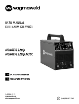
Renk Kodu ve Makara Tablosu
0,8 mm
1,0 mm
1,2 mm
1,6 mm
2,0 mm
2,4 mm
RS SerisiID Serisi Kanal Tipi Ad Ebad
Renk Kodu
7027000810 V Standart 0.8-1.0 mm
7027001012 V Standart 1.0-1.2 mm
7027001216 V Standart 1.2-1.6 mm
7027002024 V Standart 2.0-2.4 mm
7027010810 U Alüminyum Tel Uyumlu 0.8-1.0 mm
0.8-1.0 mm
7027011012 U Alüminyum Tel Uyumlu 1.0-1.2 mm
7027011216 U Alüminyum Tel Uyumlu 1.2-1.6 mm
7027012024 U Alüminyum Tel Uyumlu 2.0-2.4 mm
7027400810
-Düz Üst Makara -7027400000
7027401012
7027401216
7027402024
7027410810
7027411012
7027411216
7027412024
7027021012 Tırtıklı Özlü Tel Uyumlu 1.0-1.2 mm
7027021216 Tırtıklı Özlü Tel Uyumlu 1.2-1.6 mm
7027022024
7027421012
7027020810 Tırtıklı Özlü Tel Uyumlu
7027420810
7027421216
7027422024 Tırtıklı Özlü Tel Uyumlu 2.0-2.4 mm
0,8 mm
0,8 mm 0,8 mm
0,8 mm
TEL SÜRME SİSTEMİ HIZLI KULLANIM KILAVUZU
5-) MAKARA DEĞİŞİMİ VE BASKI AYARLARININ YAPILMASI
Makara Değişimi







Tel Makara Sökülmesi (RS SERİSİ) Tel Makara Sökülmesi (ID SERİSİ)
Tel Makara Takılması (RS SERİSİ) Tel Makara Takılması (ID SERİSİ)
TEL SÜRME SİSTEMİ HIZLI KULLANIM KILAVUZU
Makara Baskı Ayarı


 






 

 

 
Magma Mekatronik Makine Sanayi ve Ticaret A.Ş.

T: (236) 226 27 00
F: (236) 226 27 28
19.10.2021

(+90) 538 927 12 62
(+90) 444 93 53
magmaweld.com
info@magmaweld.com
  • Page 1 1
  • Page 2 2
  • Page 3 3
  • Page 4 4
  • Page 5 5
  • Page 6 6
  • Page 7 7
  • Page 8 8
  • Page 9 9
  • Page 10 10

Magmaweld 979 QS User manual

Type
User manual
This manual is also suitable for

Ask a question and I''ll find the answer in the document

Finding information in a document is now easier with AI

in other languages