Page is loading ...

51-01 Cypress 51-10C Classico
51-03 Vesuvius 51-10CP Hammered Copper
51-07 Ziggurat 51-10H Hacienda
51-08 Santorini 51-10R Richmond
51-08C Classico 51-11 Santorini
51-08CP Hammered Copper 51-16 Vulsini
51-08H Hacienda 51-16V Viento
51-08R Richmond 51-22 Vulsini
51-10 Santorini 51-37 Santorini
CODE AND SUPPLY REQUIREMENTS: When an appliance is for connection to a fixed piping system, the installation
must conform with local codes, or in the absence of local codes, with the National Fuel Gas Code, ANSI Z223.1/NFPA
54, International Fuel Gas Code, Natural Gas and Propane Installation Code, CSA B149.1, or Propane Storage and
Handling Code, B149.2, as applicable.
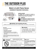
WARNING: FOR OUTDOOR USE ONLY
This appliance is designed as an
“attended appliance”. Adults must be
present when the unit is operating.
DO NOT leave this unit burning when
unattended. If this product is left burning
unattended it may cause damage or
serious injury.
WARNING
Improper installation, adjustment,
alteration, service or maintenance can
cause injury or property damage. Read
the installation, operating and
maintenance instructions thoroughly
before installing or servicing this
equipment.
WARNING
Do not store or use gasoline or other flammable vapors and liquids in the
vicinity of this or any other appliance.
An LP-cylinder not connected for use shall not be stored within 60" of this
unit or any other appliance.
If you smell gas:
1. Shut off gas to the appliance.
2. Extinguish any open flame.
3. If odor continues, keep away from the appliance and immediately call
your gas supplier or fire department.
CARBON MONOXIDE HAZARD
This appliance can produce carbon
monoxide which has no odor.
Using it in an enclosed space can kill you.
Never use this appliance in an enclosed
space such as a camper, tent, car, or
home
INSTALLER - Owner’s Manual must be left with
the consumer for future reference.
CONSUMER – Owner’s Manual must be saved
for future reference.
OWNER'S MANUAL
CASUAL FIRESIDE
A HIGHER STANDARD IN QUALITY AND APPEARANCE - SAFE AND BEAUTIFUL OUTDOOR
FIRE PIT FOR PROPANE AND *NATURAL GAS
* Needs Conversion Kit
Report #521-O-02-5
http://www.owlee.com/technical-information.aspx
Tested & Certified to
ANSI Z21.97-2014/CSA 2.41-2014
CGA 2.17-M91 (R2009)
TM
DANGER
DANGER
* Select link below to download French instructions.
* Sélectionnezlelienci‐dessouspour
téléchargerlesinstructionsfrançaises.
V2-070515

Cover - Important Safety Information 1
Table Of Contents 2
Important Safety Information
Minimum Clearances to Combustibles 2
Pre-Installation & Preparation Guidelines 3
Installation Information
Connecting the Gas to the Fire Pit 5
Certified Media List 6
Glass Media Installation 6
Gem, Mirriored, Tumbled Glass and Ceramic Log Installation 7
Ceramic Rock and Sphere Media Installation 8
Operation Instructions 9
Lighting Instructions 9
Operating Instructions 4
Conversion to a Different Gas Type 10
A.
B.
C.
D.
OUTDOOR FIRE PIT - TABLE OF CONTENTS
IMPORTANT SAFETY INFORMATION
READ THESE INSTRUCTIONS FULLY BEFORE INSTALLING THIS OUTDOOR FIRE PIT.
If not installed and used correctly per these instructions,
this product can cause serious injury and or property damage
.
Be sure you understand all safety precautions and warnings contained in this manual.
CHECK STATE AND LOCAL CODES TO DETERMINE IF THE OUTDOOR FIRE PIT IS PERMITTED IN
YOUR LOCALITY BEFORE INSTALLATION.
If you have any questions, please contact O.W. Lee at (800) 776-9533
Page 2
Clearances to Combustible Construction:
Sidewalls: 60” (1.5 m) from center of unit (Figure 1)
Ceiling: 60” (1.5 m) from top of unit to ceiling or overhang
Flooring: 0” – Can be installed on deck, slab, floor, etc.
CAUTION: INSTALLATION, MODIFICATION AND REPAIR MUST BE DONE BY
A CERTIFIED, PROFESSIONAL TECHNICIAN or LICENCED PLUMBER.
FOR OUTDOOR USE ONLY. THIS UNIT MUST BE INSTALLED AT LEAST 60” FROM CENTER OF BURNER
TO ANY COMBUSTIBLE WALLS, CEILINGS, OR MATERIAL.
WARNING: CARBON MONOXIDE POISONING MAY LEAD TO DEATH. DO NOT MODIFY THIS OUTDOOR
FIRE PIT OR ITS CONTROLS, EXCEPT AS PROVIDED FOR IN THIS MANUAL.
Any other change may be dangerous. Improper installation or use of your Outdoor Fire Pit can cause serious
injury or death from fire, burns, explosions or carbon monoxide poisoning.
MINIMUM CLEARANCE TO COMBUSTIBLES
The dimensions shown in Figure 1 are MINIMUM
CLEARANCES to maintain when you install this Outdoor
Fire Pit. THERE MUST BE AT LEAST 60” of clearance
from the center of the unit to any combustible sidewalls,
ceilings, or material.
Figure 1
When shutting the unit down—be sure to TURN THE CONTROL VALVE FULLY OFF ON THE FIRE PIT and
close the valve on the PROPANE TANK or NATURAL GAS supply.
NOTE
MINIMUM OF 60” (1.5 m) CLEARANCE ABOVE THE
OUTDOOR FIRE PIT IF INSTALLED UNDER CEILING OR
OVERHANG
60” (1.5 m)
CLEARANCE
FROM CENTER
TO ANY
COMBUSTIBLE
CONSTRUCTION
60” (1.5 m)
CLEARANCE
FROM CENTER
TO ANY
COMBUSTIBLE
CONSTRUCTION

D.
E.
IMPORTANT SAFETY INFORMATION
A. Before installing this Outdoor Fire Pit, check “Minimum Clearance to Combustibles” on page 2.
MINIMUM CLEARANCES must be maintained when you install this Outdoor Fire Pit. THERE MUST
BE AT LEAST 60”
(
1.5 m
)
from the center of the burner to an
y
combustible sidewall, ceilin
g
, or material.
The Outdoor Fire Pit is for outdoor use only. DO NOT install or use this appliance inside a building,
garage, or any other enclosed area including recreational vehicles and/or boats. This unit must be
installed in such a manner that proper air ventilation is maintained without obstruction at all times, and
durin
g
all weather conditions.
B.
CHECK GAS TYPE (natural gas or propane): The gas supply you intend to use may not be the same as that
stated on your outdoor rating plate. THIS FIRE PIT IS CONSTRUCTED FOR USE WITH PROPANE GAS. If the
gas supply is different, or you wish to change to natural gas, you MUST have the Fire Pit Converted (method
described on page 8) to the gas type you intend to use, by a qualified, professional technician. If you are
unsure
,
contact
y
our dealer for assistance.
C.
DO NOT USE IF GAS PRESSURE IS LOWER THAN THE MINIMUM REQUIREMENT OR EXCEEDS THE
MAXIMUM.
F. Gas piping system must be sized to provide minimum inlet pressure at the maximum flow rate (BTU/hr). Undue
pressure loss will occur if the pipe is too small or the run is too long.
Page3
FOR NATURAL GAS: The minimum inlet gas supply pressure for purposes of input adjustment is 5 inches (127
mm) water column and maximum inlet gas supply pressure is 10 inches (254 mm) water column.
FOR PROPANE: The minimum inlet gas supply pressure for purposes of input adjustment is 8 inches
(203 mm) water column and the maximum inlet gas supply pressure is 13 inches (330 mm) water column.
DO NOT INSTALL THIS UNIT IF MINIMUM PRESSURE IS NOT AVAILABLE OR IF MAXIMUM PRESSURE IS
EXCEEDED.
G.
If the Outdoor Fire Pit is connected to Natural Gas, its main gas valve must be disconnected from the gas supply
piping system during any pressure testing of that system at test pressures in excess of ½ psi (3.5kPa).
INSTALLER NOTE: This unit should be installed so that it can be removed at a later date for service.
GAS SUPPLY PLUMBING REQUIREMENTS
Apply only joint compounds that are resistant to all gasses on all male pipe fittings. Make sure to tighten every
j
oint securel
y
. Do not use
p
i
p
e
j
oint com
p
ound to connect flare fittin
g
s.
I.
J.
SAFETY NOTE: An external on/off valve in the gas line is required for safety when your Outdoor
Fire Pit is not in use. It also provides for convenient maintenance and repair.
K.
Casual Fireside Fire Pits are suitable for installation from 0 - 4500 ft. without modification.
H.
If the Outdoor Fire Pit is connected to Natural Gas, it must be isolated from the gas supply piping system by
closing its individual manual shut-off valve during any pressure testing of the gas supply piping system at test
pressures equal to or less than ½ psi (3.5kPa).
L. Propane Regulator Hose: Always inspect the condition of the propane regulator hose before each operation.
A
n
y
si
g
ns of excessive abrasion MUST BE REPLACED. Contact
y
our local dealer for re
p
lacement
p
art
Location Regulator Hose (when used): The propane regulator hose is located inside the fire pit door panel.
When installed, make sure the hose is secured inside the unit and DOES NOT TOUCH THE BURNER PAN.
M.

M.
Periodically make a visual check of the burner flames - see pictorial representation below for proper flame height
N.
Cleaning of appliance – Remove lava rock or glass crystals, clean burner with soap and water and dry thoroughly.
Clean lava rock or glass crystals with water and dry thoroughly before lighting.
Page4Pictorialrepresentationofapproximateflameheight.
I.
DO NOT use this appliance if any part of it has been under water. Immediately call a qualified service
technician to inspect the appliance and to replace any part of the control system and any gas control which has
been under water.
J.
Installation and repair should be done by a qualified licensed service technician. Open the door on the unit
to
g
ain access for ins
p
ection
K.
The appliance should be inspected before use and at least annually by a qualified licensed service
technician. More frequent cleaning may be required as necessary. It is imperative that control compartment,
burners and circulating air passageways of the appliance be kept clean and free from insects, spider webs or any
t
yp
e of obstruction.
L.
The burner must be replaced prior to the appliance being put into operation if it is evident that the burner is
damaged. Replacement burner #COM0590 manufactured by O.W. Lee Company, 1822 E. Francis Street, Ontario
CA 91761
IMPORTANT SAFETY INFORMATION
A.
YOUNG CHILDREN SHOULD BE CAREFULLY SUPERVISED WHEN THEY ARE IN THE AREA OF THIS
APPLIANCE.
OPERATING INSTRUCTIONS
DO NOT sit or place any part of the body or combustible materials on the Fire Pit surround. Children and
adults should be alerted to the hazard of high surface temperatures and should stay away to avoid burns
or clothing ignition.
B.
C.
Every time you use your Fire Pit make sure that the area around the Fire Pit is clear of flammable items such as
gasoline, yard debris, wood, etc.
G.
DO NOT store any combustible materials, gasoline, or any other flammable vapors/liquids around the area of your
Fire Pit. Provide ade
q
uate clearance for servicin
g
and o
p
eration.
H.
Clothing or other flammable materials should not be hung from the appliance, or placed on or near the
appliance. Matches, paper, garbage, or any other material must not be thrown on top of the lava rock, logs, or
burner
,
or into the flame.
WARNING: HOT WHILE IN OPERATION AND FOLLOWING OPERATION. Children must be carefully
supervised when in the vicinity of this appliance. Serious injury may occur. DO NOT throw trash, paper, or other
flammable materials onto your Fire Pit. DO NOT leave in operation when unattended.
WARNING: DO NOT o
p
erate this Fire Pit in the rain.
D.
E. SOLIDFUELMUSTNOTBEBURNEDintheFirePit.
F. DONOTcontinueusingifyousmellunusualodorsorhaveheadaches,nauseaoraredizzy.

LP-GAS CYLINDER INFORMATION:
C
ylinder
S
ize:
20
Lbs.
(9
kg
)
C
apacity: 4.7
G
allons
(1
7.
8
Liters
)
.
BEFORE INSTALLATION, BE SURE THE PROPANE TANK IS TURNED OFF.
Turn on the gas to the burner system and test for leaks with soapy water solution.
(Never use an open flame for testing). If a leak is found, tighten the connector until no leaks are detected.
The hose and burner should be inspected before each use of the appliance.
The hose assembly must be replaced prior to the appliance being put into operation if there is evidence of excessive
abrasion or wear, or if the hose is damaged. The replacement hose shall be that specified by the manufacturer.
Page 5
The LP-gas cylinders must be stored outdoors in a well-ventilated area out of the reach of children. Disconnected
cylinders must have threaded valve plugs tightly installed and must not be stored in a building, garage, or any
other enclosed area.
5.
6.
The cylinder supply system must be arranged for vapor withdrawal.
1.
The LP-gas cylinder(s) to be used must be constructed and marked in accordance with the U.S. Department of
Transportation (D.O.T.) Specifications for LP-Gas Cylinders or the Standard for Cylinders, Spheres and Tubes for
Transportation of Dangerous Goods and Commission, CAN/CSA-B339 as applicable.
--Use propane cylinders approved for your area such as “Blue Rhino” or “AmeriGas” with this appliance. Other
cylinders may be acceptable for use with the appliance provided they can be mounted to the appliance using the
cylinder retention devise provided. (See illustration above.)
--The LP-gas supply cylinder to be used must be provided with a listed overfilling prevention device and with a
c
y
linder connection device com
p
atible with the connection for the a
pp
liance.
2.
3.
If the appliance is not in use, the gas must be turned off at the supply cylinder.
The cylinder must be disconnected when the appliance is not in use.
4.
C. MinimumClearancetoCombustibles(page2).
INSTALLATION INFORMATION
CONNECTING THE GAS TO THE FIRE PIT
IMPORTANT
BEFORE PROCEEDING, CAREFULLY READ ALL OF THE IMPORTANT SAFETY
INFORMATION CONTAINED IN THIS OWNER'S MANUAL, INCLUDING:
A. Pre‐InstallationandOutdoorFirePitPreparationSafetyGuidelines(page3).
B. MediaInstallationGuidelines(Page6‐8).

Page6
#1 Stainless Steel Rectangle Burner Kit
#2 Propane Regulator
#3 On/Off Control Knob
#4 Brass Replacement Valve
#5 Whisper Quiet Flex Line 22"
#6 Brass Fitting
#7 Orifice Propane
#8 Propane to Natural Gas Conversion Kit
#9 Natural Gas to Propane Conversion Kit
Approved Media:
#10 Lava Granules 3/8"
#11 Pebble Fire Glass Kit – Size #3 3/4” – ½” (9-19mm)
#12 Tumbled Fire Glass Kit –Size #3 3/8” – ½” (9-12 mm)
#13 Ceramic Rock Kit with Lava Granules
#14 Ceramic Sphere Kit with Lava Granules
#15 Ceramic Log Kit with Lava Granules
#16 Mirriored Glass Kit - Size 1/4" - (6.35mm)
LAVA GRANULES PLACEMENT
LAVA GRANULES AND GLASS MEDIA PLACEMENT
LAVA GRANULES MEDIA PLACEMENT
A.
Carefully inspect the carton for shipping damage. If any parts are missing or damaged, call your dealer.
Do not attem
p
t to install the a
pp
liance unless all
p
arts are in
g
ood condition.
B. CorrectinstallationiscrucialtosafeperformanceofyourOutdoorFirePit.
C. Duetohightemperatures,theFirePitmustbelocatedoutoftrafficareasandawayfromcombustibles.
CAUTION: BURN HAZARD. LAVA GRANULES
WILL REMAIN HOT FOR SOME TIME AFTER USE.
YOU MUST MAINTAIN THE LAYOUT AS SHOWN TO ENSURE PROPER OPERATION OF YOUR FIRE PIT.
IF YOU NEED TO REPOSITION ANY MATERIAL TO MAINTAIN THE PROPER LAYOUT, USE HEAT
RESISTANT GLOVES OR ALLOW MATERIAL ADEQUATE TIME TO COOL BEFORE HANDLING.
Pour the bag of lava granules media into the
Outdoor Fire Pit so that the burner is completely covered.
See parts list above for approved media.
(See figures #1 and #2)
Figure#2Figure#1
REPLACEMENTPARTSANDMEDIAAREAVAILABLETHROUGHYOURLOCALDEALER

Page7
Pour the glass gem / tumbled glass media into the
Outdoor Fire Pit so that the burner is completely covered.
(See Figure 1 and 2
Figure 1.
Place the largest log diagonally
centered over the burner.
Figure 2.
Place the larger three logs as
desired using the largest log as
the support.
Figure 3.
Place the balance of the logs as
desired. Make sure to leave
enough air flow.
CERAMIC LOG MEDIA PLACEMENT
Pour the lava granules into the Outdoor Fire Pit so that the burner
is completely covers the burner by 1/2" and spread evenly.
(See Figure 1, 2 and 3)
Figure 1.
Pour the first bag of the glass media
into the burner support.
Figure 2.
Pour the additional bags of media onto the
burner support. Spread the media evenly
covering the burner.
CAUTION: BURN HAZARD. FIRE PIT MEDIA
WILL REMAIN HOT FOR SOME TIME AFTER USE.
YOU MUST MAINTAIN THE LAYOUT AS SHOWN TO ENSURE PROPER OPERATION OF YOUR FIRE PIT.
IF YOU NEED TO REPOSITION ANY MATERIAL TO MAINTAIN THE PROPER LAYOUT, USE HEAT
RESISTANT GLOVES OR ALLOW MATERIAL ADEQUATE TIME TO COOL BEFORE HANDLING.
GEM, MIRRIORED AND TUMBLED GLASS MEDIA PLACEMENT
GEM, MIRRIORED AND TUMBLED GLASS MEDIA PLACEMENT
A.
Carefully inspect the carton for shipping damage. If any parts are missing or damaged, call your dealer.
Do not attempt to install the appliance unless all parts are in
g
ood condition.
B. CorrectinstallationiscrucialtosafeperformanceofyourOutdoorFirePit.
Duetohightemperatures,theFirePitmustbelocatedoutoftrafficareasandawayfromcombustibles.C.

Figure 4.
Add the smaller spheres as
illustrated below
Figure 3.
Lay the smaller stones on top
of the larger stones allowing
gaps for proper air flow.
Figure 1.
Pour the lava granules into the
burner support covering the
burner completely.
Figure 2.
Place the larger spheres evenly
over the edge of the burner
CERAMIC ROCK AND SPHERE MEDIA PLACEMENT
CAUTION: BURN HAZARD. CERAMIC ROCK AND SPHERE MEDIA.
WILL REMAIN HOT FOR SOME TIME AFTER USE.
YOU MUST MAINTAIN THE LAYOUT AS SHOWN TO ENSURE PROPER OPERATION OF YOUR FIRE PIT.
IF YOU NEED TO REPOSITION ANY MATERIAL TO MAINTAIN THE PROPER LAYOUT, USE HEAT
RESISTANT GLOVES OR ALLOW MATERIAL ADEQUATE TIME TO COOL BEFORE HANDLING.
Ceramic Rock Placement
(See Figure 1, 2 and 3)
Page8
Ceramic Sphere Placement
(See Figure 1, 2, 3 and 4)
Figure 1.
Pour the lava granules into
the burner support.
Figure 2.
Place the larger rocks
allowing gaps for proper
air flow.
Figure 3
Add the medium spheres at the
corner and one small sphere in
the center.

Page 9
OPERTATING INSTRUCTIONS
*We recommend that before you install your Fire Pit you familiarize yourself with the control valve layout.
This will help you to be confident operating the Fire Pit when fully installed (see figures below for typical control positions).
FOR YOUR SAFETY, READ BEFORE LIGHTING
VWARNING: IF YOU DO NOT FOLLOW THESE INSTRUCTIONS EXACTLY,
A FIRE OR EXPLOSION MAY RESULT CAUSING PROPERTY DAMAGE,
PERSONAL INJURY OR LOSS OF LIFE.
BEFORE LIGHTING, smell all around the Outdoor Fire Pit
area for gas. Be sure to smell next to the floor because
propane gas is heavier than air and will settle on the floor.
IF YOU SMELL GAS FOLLOW THE INSTRUCTIONS ON
PAGE 1.
Use only your hand to push in or turn the gas control knob.
Never use tools. If the knob will not push in or turn by
hand. DO NOT try to repair it. Call a qualified,
professional service technician. Force or attempted repair
may result in fire or explosion.
DO NOT use this appliance if any part has
been under water. Immediately call a
qualified, professional service technician to
inspect the Outdoor Fire Pit and to replace
any part of the control system and any gas
control that has been under water.
LIGHTING INSTRUCTIONS
STOP - READ SAFETY INFOIRMATION ABOVE
1.
Shutting Off The Fire Pit
CAUTION:
DO NOT turn the main gas valve knob to the “ON” position FOR 5 MINUTES after shutting the unit off.
To turn off: Press in and rotate the manual gas control knob clockwise to the “OFF” position.
Push in the manual gas control knob slightly and turn clockwise to the “OFF” position.
2.
Wait 5 minutes for gas to clear out
3.
Place a burning match to the surface of the lava granules that cover the burner. Do not
hold the match by hand.
4.
After the match is burning and in position, push in the manual gas control knob slightly, and
slowly turn the knob counter-clockwise to the “ON” position.

Orifice # (Main) Work Order #
Orifice # (OTHER) Serial #
Leak Test Model #
Burn Test Air Shutter
Gas Type Inspector:
#12
LP - NAT
Casual Fireside Fire Pits Are
Suitable For Installation from
0 - 4500 ft. Without Modification.
Follow steps 1 – 5 shown above.
THE CONVERSION SHALL BE CARRIED
OUT BY A MANUFACTURER’S
AUTHORIZED REPRESENTATIVE, IN
ACCORDANCE
WITH THE REQUIREMENTS OF THE
MANUFACTURER, PROVENCIAL OR
TERRITORIAL AUTHORITIES HAVING
JURISDICTION AND IN ACCORDANCE
WITH THE REQUIREMENTS OF THE
CAN/CGA-B149.1 OR CAN/CGA-B149.2
INSTALLATION CODES.
After conversion follow Operating
Instructions found on Page 9.
MANUFACTURER’S USE ONLY - QUALITY CHECK Date
COM0590
X
#40
3.
Remove the orifice from the holder (Figure # 2 ) and replace it with the proper sized one for your gas requirement.
Propane requires the smaller orifice.
4.
If you are converting from propane (LP) gas to natural gas, install the air shutter sleeve so that the air intake holes are
closed (Figure #2). For Propane gas, remove the air shutter so that the air intake holes are open (Figure #1).
5.
IT IS NECESSARY TO ATTACH THE LABEL OR RATING PLATE INCLUDED WITH THE CONVERSION KIT TO
CLEARLY INDICATE THE FIELD CONVERSION.
FIGURE 1
FIGURE 2
CONVERTING YOUR FIRE PIT TO A DIFFERENT GAS TYPE
1.
MAKE SURE THAT THE GAS SUPPLY TO THE FIRE PIT (AND ANY NEARBY ELECTRICAL
SOURCES/APPLIANCES
)
ARE SHUT OFF.
2.
Carefully detach the flex line connector hose attached to the orifice holder (Figure # 1) and unscrew the orifice holder
from the burner pipe (Figures #1 and # 2).
Orifice OrificeHolder
Burner
Whenconverting tonaturalgas,theairshutter
sleeve MUSTbeinstalledovertheburnerpipe.
FlexLine
Connector Hose
Burner OrificeHolder FlexLine
Connector Hose
Orifice
AirIntake holeopenforLPGas
/