Page is loading ...

R151-Z30
SP3 socket motherboard for the AMD EPYC Series Processor family
Service Guide
Rev. 1.0

Copyright
© 2018 GIGA-BYTE TECHNOLOGY CO., LTD. All rights reserved.
The trademarks mentioned in this manual are legally registered to their respective owners.
Disclaimer
Information in this manual is protected by copyright laws and is the property of GIGABYTE.
Changes to the specications and features in this manual may be made by GIGABYTE without
prior notice. No part of this manual may be reproduced, copied, translated, transmitted, or pub-
lished in any form or by any means without GIGABYTE's prior written permission.
Documentation Classications
In order to assist in the use of this product, GIGABYTE provides the following types of documentations:
For detailed product information, carefully read the User's Manual.
For More Information
For related product specications, the latest rmware and software, and related information, please visit
our website at:
http://www.gigabyte.com
For GIGABYTE distributors and resellers, additional sales & marketing materials are available from our
reseller portal:
http://reseller.b2b.gigabyte.com
For further information & technical assistance, please contact your GIGABYTE sales representative.
You may also message GIGABYTE server directly by email, Facebook or twitter
Email: server[email protected]
Facebook: https://www.facebook.com/gigabyteserver
Twitter: https://twitter.com/GIGABYTEServer

Conventions
The following conventions are used in this user's guide:
NOTE!
Gives bits and pieces of additional
information related to the current topic.
CAUTION!
Gives precautionary measures to
avoid possible hardware or software problems.
WARNING!
Alerts you to any damage that might
result from doing or not doing specic actions.

Server Warnings and Cautions
Before installing a server, be sure that you understand the following warnings and cautions.
WARNING!
To reduce the risk of electric shock or damage to the equipment:
• Do not disable the power cord grounding plug. The grounding plug is an important safety
feature.
• Plug the power cord into a grounded (earthed) electrical outlet that is easily accessible at all
times.
• Unplug the power cord from the power supply to disconnect power to the equipment.
• Do not route the power cord where it can be walked on or pinched by items placed against it.
Pay particular attention to the plug, electrical outlet, and the point where the cord extends from
the server.
WARNING!
To reduce the risk of personal injury from hot surfaces, allow the drives
and the internal system components to cool before touching them.
WARNING!
This server is equipped with high speed fans. Keep away from hazardous
moving fan blades during servicing.
CAUTION!
• Do not operate the server for long periods with the access panel open or removed. Operat-
ing the server in this manner results in improper airow and improper cooling that can lead to
thermal damage.
• Danger of explosion if battery is incorrectly replaced.
• Replace only with the same or equivalent type recommended by the manufacturer.
• Dispose of used batteries according to the manufacturer’s instructions.

Electrostatic Discharge (ESD)
CAUTION!
ESD CAN DAMAGE DRIVES, BOARDS, AND OTHER PARTS. WE RECOMMEND THAT YOU
PERFORM ALL PROCEDURES AT AN ESD WORKSTATION. IF ONE IS NOT AVAILABLE,
PROVIDE SOME ESD PROTECTION BY WEARING AN ANTI-STATIC WRIST STRAP AT-
TACHED TO CHASSIS GROUND -- ANY UNPAINTED METAL SURFACE -- ON YOUR SERVER
WHEN HANDLING PARTS.
Always handle boards carefully. They can be extremely sensitive to ESD. Hold boards only by
their edges without any component and pin touching. After removing a board from its protective
wrapper or from the system, place the board component side up on a grounded, static free sur-
face. Use a conductive foam pad if available but not the board wrapper. Do not slide board over
any surface.
System power on/off: To remove power from system, you must remove the system from
rack. Make sure the system is removed from the rack before opening the chassis, adding, or
removing any non hot-plug components.
Hazardous conditions, devices and cables: Hazardous electrical conditions may be
present on power, telephone, and communication cables. Turn off the system and disconnect the
cables attached to the system before servicing it. Otherwise, personal injury or equipment dam-
age can result.
Electrostatic discharge (ESD) and ESD protection: ESD can damage drives,
boards, and other parts. We recommend that you perform all procedures in this chapter only at
an ESD workstation. If one is not available, provide some ESD protection by wearing an antistatic
wrist strap attached to chassis ground (any unpainted metal surface on the server) when handling
parts.
ESD and handling boards: Always handle boards carefully. They can be extremely
sensitive to electrostatic discharge (ESD). Hold boards only by their edges. After removing a
board from its protective wrapper or from the system, place the board component side up on a
grounded, static free surface. Use a conductive foam pad if available but not the board wrapper.
Do not slide board over any surface.
Installing or removing jumpers: A jumper is a small plastic encased conductor that slips
over two jumper pins. Some jumpers have a small tab on top that can be gripped with ngertips
or with a pair of ne needle nosed pliers. If the jumpers do not have such a tab, take care when
using needle nosed pliers to remove or install a jumper; grip the narrow sides of the jumper with
the pliers, never the wide sides. Gripping the wide sides can damage the contacts inside the
jumper, causing intermittent problems with the function controlled by that jumper. Take care to
grip with, but not squeeze, the pliers or other tool used to remove a jumper, or the pins on the
board may bend or break.

CAUTION!
Risk of explosion if battery is replaced incorrectly or with an incorrect type. Replace the battery
only with the same or equivalent type recommended by the manufacturer. Dispose of used bat-
teries according to the manufacturer’s instructions.

- 7 -
Table of Contents
Chapter 1 Hardware Installation ...................................................................................10
1-1 Installation Precautions .................................................................................. 10
1-2 Product Specications .................................................................................... 11
1-3 System Block Diagram ................................................................................... 14
Chapter 2 System Appearance ..................................................................................... 16
2-1 Front View ...................................................................................................... 16
2-2 Rear View ....................................................................................................... 16
2-3 Front Panel LED and Buttons ........................................................................ 17
2-4 Rear System LAN LEDs ................................................................................. 18
2-5 Hard Disk Drive LEDs .................................................................................... 19
2-6 Power Supply Unit LED .................................................................................. 20
Chapter 3 System Hardware Installation ......................................................................22
3-1 Removing and Installing the Chassis Cover .................................................. 23
3-2 Removing and Installing the Fan Duct ........................................................... 24
3-3 Removing and Installing the CPU and Heat Sink ........................................... 25
3-4 Removing and Installing Memory ................................................................... 27
3-4-1 8-Channel Memory Conguration ...........................................................................27
3-4-2 Removing and Installing a Memory Module ...........................................................28
3-4-3 DIMM Population Table ..........................................................................................28
3-5 Removing and Installing the PCI Expansion Card ......................................... 30
3-6 Removing and Installing the Hard Disk Drive ................................................. 31
3-7 Installing and Removing an M.2 Solid State Drive ......................................... 32
3-8 Replacing the Fan Assembly .......................................................................... 33
3-8-1 Fan Connector Table ..............................................................................................33
3-9 Removing and Installing the Power Supply .................................................... 34
3-10 Cable Routing ................................................................................................ 35
Chapter 4 Motherboard Components ...........................................................................37
4-1 Motherboard Components ............................................................................. 37
4-2 Jumper Setting .............................................................................................. 39
Chapter 1 BIOS Setup ..................................................................................................41
5-1 The Main Menu .............................................................................................. 43
5-2 Advanced Menu ............................................................................................. 45
5-2-1 iSCSI Conguration ................................................................................................46
5-2-2 QLogic 577xx/578xx 10 Gb Ethernet BCM57810 ...................................................47

- 8 -
5-2-3 VLAN Conguration ................................................................................................60
5-2-4 CPU Conguration ..................................................................................................62
5-2-5 SATA Conguration.................................................................................................64
5-2-6 USB Conguration ..................................................................................................65
5-2-7 AST2500 Super IO Conguration ...........................................................................67
5-2-8 Serial Port Console Redirection .............................................................................70
5-2-9 PCI Subsystem Settings .........................................................................................75
5-2-10 Network Stack ........................................................................................................77
5-2-11 CSM Conguration .................................................................................................78
5-2-12 Trusted Computing .................................................................................................80
5-2-13 NVMe Conguration ...............................................................................................81
5-3 AMD CBS Menu ............................................................................................. 82
5-3-1 Zen Common Options ............................................................................................83
5-3-2 DF Common Options ..............................................................................................86
5-3-3 UMC Common Options ..........................................................................................87
5-3-4 NBIO Common Options ..........................................................................................94
5-3-5 FCH Common Options ...........................................................................................95
5-4 Chipset Setup Menu ....................................................................................... 97
5-4-1 North Bridge ...........................................................................................................98
5-4-2 Error Management ................................................................................................101
5-5 Server Management Menu ........................................................................... 102
5-5-1 System Event Log ................................................................................................104
5-5-2 View FRU Information ..........................................................................................105
5-5-3 BMC Network Conguration .................................................................................106
5-5-4 IPv6 BMC Network Conguration .........................................................................108
5-6 Security Menu .............................................................................................. 110
5-6-1 Secure Boot .......................................................................................................... 111
5-7 Boot Menu .................................................................................................... 115
5-7-1 UEFI NETWORK Drive BBS Priorities ................................................................117
5-7-2 UEFI Application Boot Priorities ................................................................. 118
5-8 Save & Exit Menu ......................................................................................... 119
5-9 ABL POST Codes ........................................................................................ 120
5-9-1 StartProcessorTestPoints .....................................................................................120
5-9-2 Memory test points ...............................................................................................120
5-9-3 PMU Test Points ...................................................................................................120
5-9-4 Original Post Code ...............................................................................................121
5-9-5 CPU test points .....................................................................................................122
5-9-6 Topology test points .............................................................................................. 122
5-9-7 Extended memory test point .................................................................................122
5-9-8 Gnb Earlier init ......................................................................................................123
5-9-9 PMU test points ....................................................................................................126

- 9 -
5-9-10 ABL0 test points ...................................................................................................126
5-9-11 ABL5 test points ...................................................................................................126
5-10 Agesa POST Codes ..................................................................................... 130
5-10-1 Universal Post Code .............................................................................................130
5-10-2 [0xA1XX] For CZ only memory Postcodes ...........................................................130
5-10-3 S3 Interface Post Code ........................................................................................133
5-10-4 PMU Post Code ....................................................................................................133
5-10-5 [0xA5XX] assigned for AGESA PSP Module ........................................................133
5-10-6 [0xA9XX, 0xAAXX] assigned for AGESA NBIO Module .......................................136
5-10-7 [0xACXX] assigned for AGESA CCX Module .......................................................138
5-10-8 [0xADXX] assigned for AGESA DF Module ..........................................................139
5-10-9 [0xAFXX] assigned for AGESA FCH Module ........................................................139
5-11 BIOS POST Beep code (AMI standard) ....................................................... 141
5-11-1 PEI Beep Codes ...................................................................................................141
5-11-2 DXE Beep Codes .................................................................................................141
5-12 BIOS Recovery Instruction ........................................................................... 142

- 10 - Hardware Installation
1-1 Installation Precautions
The motherboard/system contain numerous delicate electronic circuits and components which
can become damaged as a result of electrostatic discharge (ESD). Prior to installation, carefully
read the service guide and follow these procedures:
• Priortoinstallation, do not remove orbreakmotherboardS/N (Serial Number) sticker or
warrantystickerprovidedbyyourdealer.Thesestickersarerequiredforwarrantyvalidation.
• AlwaysremovetheACpowerbyunpluggingthepowercordfromthepoweroutletbefore
installing or removing the motherboard or other hardware components.
• Whenconnectinghardwarecomponentstotheinternal connectorsonthe motherboard,
makesuretheyareconnectedtightlyandsecurely.
• Whenhandlingthemotherboard,avoidtouchinganymetalleadsorconnectors.
• Itisbesttowearanelectrostaticdischarge(ESD)wriststrapwhenhandlingelectronic
componentssuchasa motherboard,CPU ormemory.Ifyoudonothavean ESDwrist
strap,keepyourhandsdryandrsttouchametalobjecttoeliminatestaticelectricity.
•
Prior to installing the motherboard, please have it on top of an antistatic pad or within an
electrostatic shielding container.
• Beforeunpluggingthe powersupplycablefromthemotherboard,makesurethepower
supply has been turned off.
• Beforeturningonthepower,makesurethepowersupplyvoltagehasbeensetaccordingto
the local voltage standard.
• Beforeusingtheproduct,pleaseverifythatallcablesandpowerconnectorsofyour
hardware components are connected.
• To prevent damage to the motherboard, do notallowscrewstocomeincontact with the
motherboard circuit or its components.
• Makesuretherearenoleftoverscrewsormetalcomponentsplacedonthemotherboardor
within the computer casing.
• Donotplacethecomputersystemonanunevensurface
.
• Donotplacethecomputersysteminahigh-temperatureenvironment.
• Turningonthecomputerpowerduringtheinstallationprocesscanleadtodamageto
system components as well as physical harm to the user.
• Ifyouareuncertainaboutanyinstallationstepsorhaveaproblemrelatedtotheuseofthe
product,pleaseconsultacertiedcomputertechnician.
Chapter 1 Hardware Installation

Hardware Installation - 11 -
1-2 Product Specications
CPU AMDEPYC™7000seriesprocessorfamily
Singleprocessor,14nm,SocketSP3
Upto32-core,64threads
TDPupto180W
Chipset SystemonChip
Memory 16xDIMMslots
DDR4 memory supported only
8-channel memory architecture
RDIMMmodulesupto32GBsupported
LRDIMMmodulesupto64GBsupported
Memoryspeed:2667(1DPC)/2400/2133*MHz
Note: Memory speed runs at2133MHz when 1R/2R memory modulesare
fully populated
LAN 2xSFP+10Gb/sLANports(Broadcom®BCM57810S)
1x10/100/1000managementLAN
ExpansionSlot 1xRisercard:
-1xCRS1013
*1xFull-heighthalf-lengthslotwithPCIex16(Gen3x16bus)slot
1xM.2slot:
-M-key
-PCIeGen3x4
-SupportsNGFF-2280/2260/2242cards
Video IntegratedinAspeed®AST2500
2DVideoGraphicAdapterwithPCIebusinterface
1920x1200@60Hz32bpp
Storage 4x3.5"SATA/SAShot-swappableHDD/SSDbays
2.5"HDD/SSDsupported
SAScardisrequiredforSASdevicessupport
SAS Supportedviaadd-onSASCard

-12- Hardware Installation
Internal
Connectors
1x24-pinATXmainpowerconnector
2x8-pinATX12Vpowerconnectors
4xSlimSASconnectors
1xM.2slot
2xCPUfanheaders
5xSystemfanheaders
1xUSB3.0header
1xUSB2.0header
1xCOM_2header
1xTPMheader
1xFrontpanelheader
2xLANactivityLED
1xHDDbackplaneboardheader
1xPMBusconnector
1xIPMBconnector
1xClearCMOSjumper
1xBIOSrecoveryjumper
1xBuzzer
FrontPanel
LED/Buttons
2xUSB3.0
1xPowerbuttonwithLED
1xIDbuttonwithLED
1xResetbutton
1xNMIbutton
1xSystemstatusLED
1xHDDactivityLED
2xLANactivityLEDs
RearPanelI/O 2xUSB3.0
2xUSB2.0
1xVGA
1xCOM_1
2xSFP+
1xMLAN
1xIDbuttonwithLED
BackplaneI/O 4xSATA/SASports
Bandwidth:SATAIII6Gb/sorSAS12Gb/sperport
SAScardisrequiredforSASdevicessupport
TPM 1xTPMheaderwithLPCinterface
OptionalTPM2.0kit:CTM000

Hardware Installation -13-
System
Management
Aspeed®AST2500managementcontroller
Avocent®MergePointIPMI2.0webinterface:
Networksettings
Networksecuritysettings
Hardwareinformation
Userscontrol
Services settings
IPMIsettings
Sessions control
LDAPsettings
Power control
Fanproles
Voltages, fans and temperatures monitoring
System event log
Events management (platform events, trap settings, email settings)
SerialOverLAN
vKVM&vMedia(HTML5)
Power Supply 2x650WredundantPSUs
80PLUSPlatinum
ACinput:
-100-240Vac,50-60Hz,10-5A
DCinput:
-190-310Vdc,5-3A
DCoutput:
-650W
Environment
Ambient
Temperature
Relative
Humidity
Operatingtemperature:10°Cto35°C
Operatinghumidity:8%-80%(non-condensing)
Non-operatingtemperature:-40°Cto60°C
Non-operatinghumidity:20%-95%(non-condensing)
System
Dimension
1U
430mm(W)x43.5mm(H)x625mm(D)
*Wereservetherighttomakeanychangestotheproductspecicationsandproduct-relatedinformationwithoutprior
notice.

- 14 - Hardware Installation
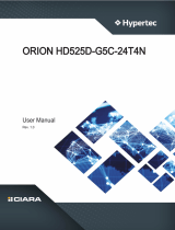
1-3 System Block Diagram
8CH DDR4
R-DIMM
2DPC
MLAN
M.2 M Key
GL850
USB HUB
GL850
USB HUB
LPC
PCIE X1
MGNT BUS
REALTEK
RTL8211
PHY
RGMII
DDR4
VRAM
SPI
PCIE3.0 X 16
R151-Z30 Block Diagram
USB2.0 X 2USB2.0 X 2USB2.0 X 2
USB2.0 X 2
FUSB2.0
PCIE3.0 X 4
SATA3.0 X 16 4 x SlimLine SAS
ASPEED
AST2500
RUSB2.0 RUSB3.0 FUSB3.0
USB3.0 X 4
VGA
COM_1
COM_2
PCIE3.0 X8
Broadcom
BCM57810
2 x 10Gb SFP+
“Zen” Core
Sockets SP3
PCIe x16
CRS1013

Hardware Installation -15-

- 16 - System Appearance
Chapter 2 System Appearance
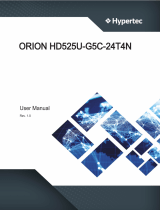
2-1 Front View
No. Description
1. USB 3.0 Ports
2. Front Panel LEDs and buttons
• RefertoChapter2-3 Front Panel LEDandButtonsforadetaileddescriptionofthefunction
oftheLEDs.
HDD #0 HDD #1 HDD #2 HDD #3
12
2-2 Rear View
No. Description
1. Serialport
2. VGAport
3. SFP+LANports
4. USB3.0ports
5. 10/100/1000ServermanagementLANport
6. USB2.0ports
7. IDbuttonwithLED
Secondary
PSU
Primary
PSU
1 2 3 4 5 6 7
• RefertoChapter2-4 Rear System LAN LEDsforadetaileddescriptionofthefunctionof
theLEDs.
Secondary
PSU
Primary
PSU
1 2 3 4 5 6 7
HDD #0 HDD #1 HDD #2 HDD #3
12

System Appearance - 17 -
2-3 Front Panel LED and Buttons
2468
1357
No. Name Color Status Description
1. NMI button -- --
PressthisbuttonfortheservertogenerateaNMItothe
processor.Ifmultiple-bitECCerrorsoccur,theserverwill
effectivelybehalted.
2. ResetButton -- -- Pressthisbuttontoresetthesystem.
3/4.
LAN 1/2
Active/Link
LEDs
Green SolidOn Indicatesalink betweenthe systemandthe networkor
noaccess.
Green Blink Indicatesdatatrasmissionorreceivingisoccuring
N/A Off Indicatesnodatatransmissionorreceivingisoccuring
5. HDD Status
LED
Green On IndicateslocatingtheHDD.
Blink IndicatesaccessingtheHDD.
Amber On IndicatesHDDerror.
Green/
Amber Blink IndicatesHDDrebuilding.
N/A Off IndicatesnoHDDaccessornoHDDerror.
6. System
Status LED
Green SolidOn Indicatessystemisoperatingnormally.
Amber
SolidOn
Indicatesacriticalcondition,mayinclude:
-Systemfanfailure
-Systemtemperature
Blink
Indicatesnon-criticalcondition,mayinclude:
-Redundantpowermodulefailure
-Temperatureandvoltageissue
-Chassisintrusion
N/A Off
Indicatessystemisnotready,mayinclude:
-POSTerror
-NMI error
-Processororterminatorismissing
7. ID Button -- -- Pressthisbuttontoactivatesystemidentication
8. Power button
withLED
Green On Indicatesthesystemispoweredon
Green Blink SystemisinACPIS1state(sleepmode)
N/A Off • SystemisnotpoweredonorinACPIS5state(poweroff)
• SystemisinACPIS4state(hibernatemode)

- 18 - System Appearance
2-4 Rear System LAN LEDs
No. Name Color Status Description
1.
SFP+ LAN
Link&
SpeedLED
Yellow On 1Gbpsdatarate
Green On 10Gbpsdatarate
2.
SFP+ LAN
Activity
LED
Green On Linkbetweensystemand
networkornoaccess
Green Blink Datatransmissionorreceivingisoccurring
N/A Off Nodatatransmissionor
receivingisoccurring
3.
10/100/
1000 LAN
LED
Yellow On 1Gbpsdatarate
Green On 100Mbpsdatarate
N/A Off 10Mbpsdatarate
4. ID button/
LED
Blue On Systemidenticationisactive
N/A Off Systemidenticationisdisabled
2
1
2
1
3 4

System Appearance - 19 -
2-5 Hard Disk Drive LEDs
LED #1
LED #2 (RESERVE)
RAID SKU HDD Fault
Locate HDD
Access
HDD Present
(No Access)
No RAID configuration
(via HBA, PCH)
RAID configuration
(via HW RAID Card or
SW RAID Card)
Disk LED
(LED on
Back Panel)
Amber
Removed HDD Slot
(LED on Back Panel)
Disk LED
Removed HDD Slot
Green ON(*1) OFF BLINK (*2)
BLINK (*2)
OFF
OFF
OFF
ON
OFF
ON(*1)
OFF
OFF
ON
OFF
ON
(Low Speed: 2 Hz)
(*3)
(*3)
OFF
OFF
--
--
Green
Amber
Green
ON(*1) OFF --
--
--
--
--
Green
OFF OFF --
Amber
Amber OFF OFF
Rebuilding
OFF
LED1
NOTE:
*1:DependsonHBA/UtilitySpec.
*2:BlinkcycledependsonHDD'sactivitysignal.
*3:IfHDDispulledoutduringrebuilding,thediskstatusofthisHDDisregardedasfaulty.

- 20 - System Appearance
2-6 Power Supply Unit LED
Power Supply Status LED
State Description
Off NoACpowertoallpowersupplies
0.5HzBlink/Red N+1,NoACpowertoallpowersupplies
Green/Blink OnlystandbyoutputON
Green PowersupplyDCoutputONandOK
Red Powersupplyfailure
0.5HzBlinkGren/Red Powersupplywarning
/