Page is loading ...

214 US Gal (810L) Horizontal
Rainwater Collecting Tank System
March 2009
Revision 03
Installation Instructions
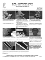
1. If packaged in a box, open the box carefully
tipping the tank on it’s side. Remove the man
way cover by rotating it as indicated on the lid.
Remove components inside of tank.
note: do not use a sharp object to open the box
in order to avoid damaging the tank or other
components.
214 US Gal (810L)
Rotational molded PE tank
Flexible downspout
Submersible Sump Pump
Leaf-catcher
Drain with Plug
Spigot
Inlet Pipe
Access Cover
Overfl ow Elbow
RTS Rainwater Collecting System
provides an effi cient, economical
and unique way to store rainwater.
Rainwater stored in the collecting
tank is mostly used for watering
landscapes and gardens.
Using the collected rainwater
can have a signifi cant impact on
your water bill and reduce your
dependency on the municipal
water supply, especially during the
hot, dry summer months.
RAINWATER COLLECTION SYSTEM
USER INSTRUCTIONS
Read these instructions and general information to properly and safely unpack and setup
your rainwater collection system. You are responsible for the safe and proper installation
and use of the product
PAGE 1/3RTS Companies Inc. | 1027 Industrial Place, P.O. Box 179, St. Clements, ON N0B 2M0 | 1-800-663-2803
2. Remove the submersible pump in the tank
by pulling the fl exible hose. Take the pump
out of it’s cardboard box and hold on to any
documentation for later reference.
3. Place the pump back into the tank as shown.
Ensure that the fl exible hose is completely
inside the tank.

4. Open the leaf catcher box and ensure none
of the components are missing or damaged.
The box should contain the following: (a) leaf
catcher, (b) brass spigot, (c) overfl ow elbow and
(d) small roll of Tefl on tape. Instructions will also
be included in this box.
5. A location should be selected close to an
existing downspout and relatively close to
the house to prevent obstruction and ease
of installation. Be aware of the dimension of
each tank, and ensure that there is more than
enough space for the tank to be permanently
placed into that location.
6. Clear the location from obstructions and
even out the area with a spade, shovel or rake,
depending on the existing surface. The ground
below the tank must be level to prevent the
tank from slopping. It is suggested the grade
be slightly tilting in towards the building so that
the tank leans just slightly towards the building
and not away from it.
7. The best solution for placing the tank is
to have a solid base which can be made of
large patio stones / walkway stones or to pour
a concrete base. Lay the stones into place
providing enough area for the footing of the
tank.
8. Level the stones to ensure that the tank sits
fl at and does not tilt and risk tipping. Adjust
as required. Check for fi nal level and place the
tank in position.
9. Position the tank leaving at least 3 inches of
space from the wall. Be aware that the spigot
goes on the bulkhead that is attached to the
pump and fl exible hose. Check for clearance on
all sides and be sure the tank is not creating an
obstruction for anything else.
10. Using the provided roll of tefl on tape, wrap
2 layers of tape on threads of the spigot and
the overfl ow elbow to ensure proper installation
and seals.
PAGE 2/3RTS Companies Inc. | 1027 Industrial Place, P.O. Box 179, St. Clements, ON N0B 2M0 | 1-800-663-2803
12. The other bulkhead at the top edge of
the tank in used for the overfl ow. Attach the
overfl ow elbow and hand tighten. A hose can
be attached to redirect water overfl ow.
11. Attach the spigot to the bulkhead
connected to the pump inside the tank and
hand tighten. Using an adjustable wrench,
tighten the spigot another full rotation after
hand tightening.

17. Attach a hose to the spigot if desired and
plug the pump electrical chord into a GFI outlet
for operation.
Note: Ensure that the unit is unplugged when
not in use.
14. Locate the existing downspout that you
will be using and remove sections of the
downspout so that the remaining pipe is at
least 1ft. higher than the top of the tank. Place
the leaf catcher in position with the grate facing
up, and using a 1/8” drill bit, drill through the
leaf catcher and the downspout.
15. Using the provided screws attach the leaf
catcher to the downspout. Use two screws at
this connection.
16. Place the square end of the fl exible
downspout in place and using a 1/8” drill bit
and the provided hardware, attach the fl exible
downspout to the leaf catcher. Use two screws
at this connection.
PAGE 3/3RTS Companies Inc. | 1027 Industrial Place, P.O. Box 179, St. Clements, ON N0B 2M0 | 1-800-663-2803
13. Place the access cover / lid in place and
lock into position.
Please Contact RTS Companies for
any questions or concerns
RTS Companies Inc.
1027 Industrial Place
P.O. Box 179, St. Clements
Ontario N0B 2M0
1-800-663-2803
/


