
Freescale Semiconductor
Hardware User Guide for i.MX53 Quick Start Board, Preliminary Rev 0.91 i
PUBI – Public Use Business Information
Hardware Reference Manual for i.MX53 Quick Start
i.MX53 Quick Start Board
Take your Multimedia
Experience to the max
semiconductor
f
reescale
TM

Freescale Semiconductor
Hardware User Guide for i.MX53 Quick Start Board, Preliminary Rev 0.91 ii
PUBI – Public Use Business Information
How to Reach Us:
Home Page:
www.freescale.com
E-mail:
USA/Europe or Locations Not Listed:
Freescale Semiconductor
Technical Information Center, CH370
1300 N. Alma School Road
Chandler, Arizona 85224
+1-800-521-6274 or +1-480-768-2130
Europe, Middle East, and Africa:
Freescale Halbleiter Deutschland GmbH
Technical Information Center
Schatzbogen 7
81829 Muenchen, Germany
+44 1296 380 456 (English)
+46 8 52200080 (English)
+49 89 92103 559 (German)
+33 1 69 35 48 48 (French)
Japan:
Freescale Semiconductor Japan Ltd.
Headquarters
ARCO Tower 15F
1-8-1, Shimo-Meguro, Meguro-ku,
Tokyo 153-0064, Japan
0120 191014 or +81 3 5437 9125
Asia/Pacific:
Freescale Semiconductor Hong Kong Ltd.
Technical Information Center
2 Dai King Street
Tai Po Industrial Estate
Tai Po, N.T., Hong Kong
+800 2666 8080
For Literature Requests Only:
Freescale Semiconductor Literature Distribution Center
P.O. Box 5405
Denver, Colorado 80217
1-800-441-2447 or 303-675-2140
Fax: 303-675-2150
LDCForFreescaleSemiconductor@hibbertgroup.com
Information in this document is provided solely to enable system and software
implementers to use Freescale Semiconductor products. There are no express or
implied copyright licenses granted hereunder to design or fabricate any integrated
circuits or integrated circuits based on the information in this document.
Freescale Semiconductor reserves the right to make changes without further notice
to any products herein. Freescale Semiconductor makes no warranty, representation
or guarantee regarding the suitability of its products for any particular purpose, nor
does Freescale Semiconductor assume any liability arising out of the application or
use of any product or circuit, and specifically disclaims any and all liability, including
without limitation consequential or incidental damages. “Typical” parameters that may
be provided in Freescale Semiconductor data sheets and/or specifications can and
do vary in different applications and actual performance may vary over time. All
operating parameters, including “Typicals”, must be validated for each customer
application by customer’s technical experts. Freescale Semiconductor does not
convey any license under its patent rights nor the rights of others. Freescale
Semiconductor products are not designed, intended, or authorized for use as
components in systems intended for surgical implant into the body, or other
applications intended to support or sustain life, or for any other application in which
the failure of the Freescale Semiconductor product could create a situation where
personal injury or death may occur. Should Buyer purchase or use Freescale
Semiconductor products for any such unintended or unauthorized application, Buyer
shall indemnify and hold Freescale Semiconductor and its officers, employees,
subsidiaries, affiliates, and distributors harmless against all claims, costs, damages,
and expenses, and reasonable attorney fees arising out of, directly or indirectly, any
claim of personal injury or death associated with such unintended or unauthorized
use, even if such claim alleges that Freescale Semiconductor was negligent
regarding the design or manufacture of the part.
Learn More: For more information about Freescale products, please visit
www.freescale.com.
Freescale™ and the Freescale logo are trademarks of Freescale Semiconductor, Inc.
All other product or service names are the property of their respective owners.
© Freescale Semiconductor, Inc. 2011. All rights reserved.

Freescale Semiconductor
Hardware User Guide for i.MX53 Quick Start Board, Preliminary Rev 0.91 iii
PUBI – Public Use Business Information
Hardware Reference Manual for i.MX53 Quick Start
TableofContents
1. Introduction ..........................................................................................................................................1
1.1. i.MX53‐QUICKSTARTBoardOverview.........................................................................................1
1.2. i.MX53‐QUICKSTARTBoardKitContents.....................................................................................2
2. ListofAcronyms....................................................................................................................................3
3. Specifi cations........................................................................................................................................4
3.1. i.MX535Processor........................................................................................................................4
3.2. DDR3DRAMMemory...................................................................................................................7
3.3. DialogDA9053PMIC.....................................................................................................................7
3.4.
MicroSDCardSlot(J4)...................................................................................................................8
3.5. SDCardSlot(J5)............................................................................................................................8
3.6. SATA7‐pinDataConnector(J7)....................................................................................................8
3.7. VGAVideoOutput(J8)..................................................................................................................8
3.8. LVDSVideoOutput(J9).................................................................................................................9
3.9. Ethernet(J2B)................................................................................................................................9
3.10. DualUSBHostConnector(J2A).................................................................................................9
3.11.
Micro‐BUSBDeviceConnector(J3)........................................................................................10
3.12. AudioInput/Output(J6/J18)...................................................................................................10
3.13. 5VPowerConnector(J1).........................................................................................................10
3.14. DebugUARTConnector(J16)..................................................................................................11
3.15. JTAGConnector(J15)..............................................................................................................11
3.16. ExpansionHeader(J13)...........................................................................................................12
3.17. UserInterfaceButtons............................................................................................................12
3.18. UserInterfaceLEDIndicators..................................................................................................
13
3.19. OptionalLi‐IONBatterConnector(J14)..................................................................................14
3.20. OptionalBack‐UpCoinCellposts(JP1,JP2)............................................................................14
3.21. PCBShortingTraces................................................................................................................15
4. QuickStartBoardConnectorsandExpansionPort.............................................................................15
4.1. Wall5VPowerJack(J1)...............................................................................................................16
4.2. RJ45EthernetConnector(J2B)...................................................................................................
17
4.3. VGADB15Connector(J8)...........................................................................................................18
4.4. DebugUARTDB9Connector(J16)..............................................................................................19
4.5. HeadphoneOutputConnector(J18)...........................................................................................20
4.6. MicrophoneInputConnector(J6)...............................................................................................21

Freescale Semiconductor
Hardware User Guide for i.MX53 Quick Start Board, Preliminary Rev 0.91 iv
PUBI – Public Use Business Information
4.7. DualUSBHostJack(J2)...............................................................................................................22
4.8. micro‐BUSBDeviceConnector(J3)............................................................................................23
4.9. SATA7‐pinDataConnector(J7)..................................................................................................24
4.10. SDCardConnector(J5)...........................................................................................................25
4.11. microSDCardConnector(J3)..................................................................................................26
4.12. 20‐pinARMJTAGConnector(J15)..........................................................................................27
4.13. LVDS
Connector(J9)................................................................................................................28
5. QuickStartBoardArchitectureandDesign........................................................................................29
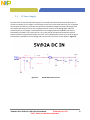
5.1. 5VPowerSupply.........................................................................................................................30
5.2. DialogDA9053PMIC...................................................................................................................31
5.2.1. QuickStartPowerRails.......................................................................................................33
5.2.2. Li‐IONBatteryCharging......................................................................................................35
5.2.3. BacklightLEDDriver............................................................................................................35
5.2.4. Touch‐ScreenOperation.....................................................................................................
36
5.2.5. Miscellaneous.....................................................................................................................36
5.3. 3.2VSecondaryVoltageRegulator.............................................................................................38
5.4. i.MX53ApplicationsProcessor....................................................................................................39
5.4.1. PeripheralModuleLogicVoltageLevels.............................................................................39
5.4.2. BootModeOperationsandSelections...............................................................................41
5.4.3. ClockSignals........................................................................................................................48
5.4.4. i.MX53InternalRegulators.................................................................................................49
5.4.5. WatchDogTimer................................................................................................................49
5.5.
DDR3SDRAMMemory................................................................................................................51
5.6. MicroSDCardConnector............................................................................................................52
5.7. FullSizeSDCardConnector........................................................................................................53
5.8. VGAVideoOutput.......................................................................................................................54
5.9. LVDSVideoOutput......................................................................................................................55
5.10. ExpansionPort........................................................................................................................56
5.11. Audio.......................................................................................................................................57
5.12. Ethernet..................................................................................................................................58
5.13. USBHostconnections.............................................................................................................
59
5.14. SATA........................................................................................................................................60
5.15. DebugUARTSerialPort...........................................................................................................61
5.16. JTAGOperations......................................................................................................................62
6. ConnectorPin‐Outs.............................................................................................................................63

Freescale Semiconductor
Hardware User Guide for i.MX53 Quick Start Board, Preliminary Rev 0.91 v
PUBI – Public Use Business Information
Hardware Reference Manual for i.MX53 Quick Start
7. BoardAccessories...............................................................................................................................80
7.1. HDMIDaughterCard...................................................................................................................80
7.2. LCDDisplayDaughterCard.........................................................................................................82
7.3. LVDSDisplaySet(ComingSoon).................................................................................................84
8. MechanicalPCBInformation..............................................................................................................86
9. BoardVerification...............................................................................................................................88
10. Troubleshooting..............................................................................................................................92
10.1. PMICVoltageRailTestPoints.................................................................................................93
11. Known
Issues...................................................................................................................................95
12. PCBComponentLocations ..............................................................................................................96
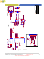
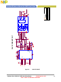
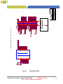
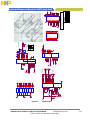
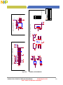
13. Schematics....................................................................................................................................101
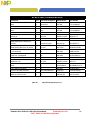
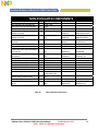
14. BillofMaterials.............................................................................................................................115
15. PCBinformation............................................................................................................................122

Freescale Semiconductor
Hardware User Guide for i.MX53 Quick Start Board, Preliminary Rev 0.91 vi
PUBI – Public Use Business Information
ListofFigures
Figure1. DCPowerJack……………………………………………………………………………………………………………16
Figure2. RJ45EthernetConnector…………………………………………………………………………………………….17
Figure3. VGAConnector…………………………………………………………………………………………………………..18
Figure4. DebugUARTConnector……………………………………………………………………………………………..19
Figure5. HeadphoneOutputConnector…………………………………………………………………………………..20
Figure6. MicrophoneConnector(J6)……………………………………………………………………………………..21
Figure7. DualUSBHostConnectors(J2)……………………………………………………………………………….….22
Figure
8. micro‐BUSBDeviceConnector(J3)…………………………………………………………………………..23
Figure9. SATADataConnector(J7)…………………………………………………………………………………………24
Figure10. SDCardConnector(J5)……………………………………………………………………………………………..25
Figure11. microSDCardConnector(J4)…………………………………………………………………………………….26
Figure12. JTAGConnector(J15)……………………………………………………………………………………….….……27
Figure13. LDVSConnector(J9)……………………………………………………………………………………..…….……..28
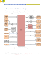
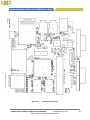
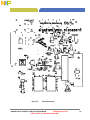
Figure14. i.MX53
Smart‐StartBlockDiagram……………………………………………………………………………..29
Figure15. BoardMainPowerCircuit.……………………………………………………………………………………….…30
Figure16. BootModeResistorLocationsTOP……………………………………………………………………………..46
Figure17. BootModeResistorLocationsBOTTOM……………………………………………………………………..47
Figure18. ClockSourceLocations……………………………………………………………………………………………….48
Figure19. WatchDogTimerResetTrigger………………………………………………………………………………….50
Figure20. PowerJack(J1) ………………………………………………………………………………………………………….64
Figure
21. Micro‐BUSBConnector(J3)……………………………………………………………………………………..64
Figure22. Ethernet/DualUSBConn(J2)……………………………………………………………………………………65
Figure23. HeadphoneConnector(J18)…………………………………………………………………………………….66
Figure24. MicrophoneConnector(J6)…………………………………………………………………………………….66
Figure25. VGADB15Connector(J8)………………………………………………………………………………………….67
Figure26. LVDSConnector(J9)………………………………………………………………………………………………….68
Figure27. SATADataConnector
(J7)………………………………………………………………………………………….69
Figure28. SDCardConnector(J5)……………………………………………………………………………………………..70
Figure29. microSDCardConnector(J4)…………………………………………………………………………………….71
Figure30. DebugUARTConnector(J16)…………………………………………………………………………………….72
Figure31. JTAGConnector(J15)………………………………………………………………………………………………..73
Figure32. ExpansionPort(J13)……………………………………………………………………………………………….…74
Figure33. OptionalHDMIDaughterCard……………………………………………………………………………………80
Figure34. MCIMX28LCD
4.3”WVGADisplayDaughterCard…………………………………………….…………82
Figure35. LVDSDisplayKit…………………………………………………………………………………………………………84
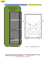
Figure36. QuickStartBoardDimensions……………………………………………………………………………………86
Figure37. EthernetLoopbackCable…………………………………………………………………………………………..91
Figure38. RegulatorOutputCapacitorPositionsBottom…………………………………………………………..93
Figure39. RegulatorOutputCapacitorPositionsTop…………………………………………………………………94
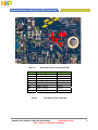
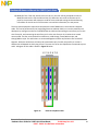
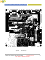
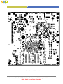
Figure40. MajorComponentHighlightsTop……………………………………………………………………………..97

Freescale Semiconductor
Hardware User Guide for i.MX53 Quick Start Board, Preliminary Rev 0.91 vii
PUBI – Public Use Business Information
Hardware Reference Manual for i.MX53 Quick Start
ListofFigures(con)
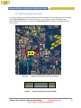
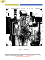
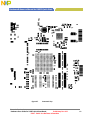
Figure41. MajorComponentHighlightsBottom…………………………………………………………………………98
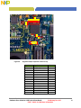
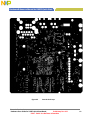
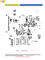
Figure42. AssemblyDrawingTop……………………………………………………………………………………………….99
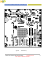
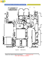
Figure43. AssemblyDrawingBottom…………………………………………………………………………………………100
Figure44. DC5VINPUT……………………………………………………………………………………………….……………..102
Figure45. MX53POWER……………………………………………………………………………………………….……………103
Figure46. MX53DDR3MEMORY…………………………………………………………………………………….………….104
Figure47. MX53CONTROL…………………………………………………………………………………………………………105
Figure48. MX53USB……………………………………………………………………………………………………….…………106
Figure49. MX53SDINTERFACE………………………………………………………………………………………….………107
Figure
50. MX53AUDIO……………………………………………………………………………………………………….…….108
Figure51. MX53SATA…………………………………………………………………………………………………………..……109
Figure52. MX53VGA……………………………………………………………………………………………………………..….110
Figure53. MX53ETHERNET…………………………………………………………………………………………………….…111
Figure54. EXPANSIONHEADER……………………………………………………………………………………………….…112
Figure55. DA9053PMIC…………………………………………………………………………………………………………….113
Figure56. DEBUG,ACCELEROMETER……………………………………………………………………………………….…114
Figure57. TopEtchLayer…………………………………………………………………………………………………………..123
Figure58. SecondEtchLayer……………………………………………………………………………………………………..124
Figure59. ThirdEtchLayer…………………………………………………………………………………………………………125
Figure60. FourthEtchLayer………………………………………………………………………………………………………126
Figure61. Fifth
EtchLayer………………………………………………………………………………………………………….127
Figure62. SixthEtchLayer………………………………………………………………………………………………………….128
Figure63. SeventhEtchLayer……………………………………………………………………………………………………..129
Figure64. BottomEtchLayer………………………………………………………………………………………………………130
Figure65. SoldermaskTop………………………………………………………………………………………………………….131
Figure66. SoldermaskBottom……………………………………………………………………………………………………132
Figure67. PastemaskTop…………………………………………………………………………………………………………..133
Figure68. PastemaskBottom……………………………………………………………………………………………………..134
Figure69. SilkscreenTop…………………………………………………………………………………………………………….135
Figure70. SilkscreenBottom………………………………………………………………………………………………………136

Freescale Semiconductor
Hardware User Guide for i.MX53 Quick Start Board, Preliminary Rev 0.91 viii
PUBI – Public Use Business Information
ListofTables
Table1. RegulatorTimingSequence…………………………………………………………………………………………32
Table2. QuickStartBoardPowerSupplyRails…………………………………………………………………………33
Table3. PortIDResistorValues……………………………………………………………………………………………….36
Table4. ModuleVoltageSupplies…………………………………………………………………………………………….40
Table5. BOOT_MODEpinSettings………………………………………………………………………………………..…41
Table6A. BOOT_CFGWord1………………………………………………………………………………………………………41
Table6B. BOOT_CFGWord2………………………………………………………………………………………………………41
Table6C. BOOT_CFGWord3………………………………………………………………………………………………………42
Table7. Boot
ModeResistorsTOP……………………………………………………………………………………………46
Table8. BootModeResistorsBOTTOM……………………………………………………………………………………47
Table9. DDR3SDRAMChipOrganization…………………………………………………………………………………51
Table10. Micro‐SDCardBootOptions………………………………………………………………………………………52
Table11. FullSizeSDCardBootOptions……………………………………………………………………………………53
Table12. SATABootModeConfigurationTable.………………………………………………………………………60
Table13. TerminalSettingParameters………………………………………………………………………………………61
Table
14. PowerJack(J1)………………………………………………………………………………………………………….64
Table15. Micro‐BUSBConnector(J3)……………………………………………………………………………………….64
Table16. Ethernet/DualUSBConn(J2)……………………………………………………………………………………..65
Table17. HeadphoneConnector(J18)………………………………………………………………………………………66
Table18. MicrophoneConnector(J6)……………………………………………………………………………………….66
Table19. VGADB15Connector(J8)………………………………………………………………………………………….67
Table20. LVDSConnector(J9)………………………………………………………………………………………………….68
Table21. SATADataConnector(J7)………………………………………………………………………………………….69
Table22. SDCardConnector(J5)………………………………………………………………………………………………70
Table23. microSDCardConnector(J4)…………………………………………………………………………………….71
Table24. DebugUARTConnector(J16)…………………………………………………………………………………….72
Table25. JTAGConnector(J15)………………………………………………………………………………………………..73
Table26. ExpansionPort(J13)………………………………………………………………………………………………….74
Table27. ExpansionPort
Pin‐MuxTable…………………………………………………………………………………….76
Table28. BoardStackupinformation…………………………………………………………………………………………87
Table29. ProblemResolutionTable…………………………………………………………………………………………..92
Table30. OutputCapacitorsandValuesBOTTOM……………………………………………………………………..93
Table31. OutputCapacitorsandValuesTOP…………………………………………………………………………….94

Freescale Semiconductor
Hardware User Guide for i.MX53 Quick Start Board, Preliminary Rev 0.91 1
PUBI – Public Use Business Information
Hardware Reference Manual for i.MX53 Quick Start
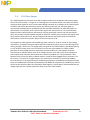
1. Introduction
ThisdocumentistheHardwareReferenceManualforthei.MX53QuickStartboardbasedonthe
FreescaleSemiconductori.MX53ApplicationsProcessor.ThisboardisfullysupportedbyFreescale
Semiconductor.ThisManualincludessystemsetupanddebugging,andprovidesdetailedinformation
ontheoveralldesignandusageofthei.MX53Quick
StartboardfromaHardwareSystemsperspective.
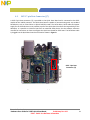
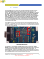
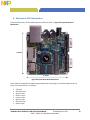
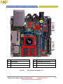
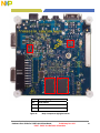
1.1. i.MX53‐QUICKSTARTBoardOverview
TheQuickStartBoardisani.MX535platformdesignedtoshowcasemanyofthemostcommonlyused
featuresofthei.MX535ApplicationsProcessorinasmall,lowcostpackage.TheMCIMX53‐STARTisan
entryleveldevelopmentboardandanearperfectsubsetofitslargersisterboard,theMCIMX53SMD,
whichisavailableasafull,near‐formfactortablet.Developerscanstartworkingwithcodeonthe
QuickStartboard,andthenportitovertotheSMDTabletifadditionalfeaturesaredesired.Thisgives
thedevelopertheoptionofbecomingfamiliarwiththei.MX535ApplicationsProcessorbeforeinvesting
alargeamountorresourcesinmorespecificdesigns.Featuresofthei.MX53QuickStartboardare:
Processor: FreescaleApplicationsProcessor MCIMX535DVV1B
DRAMMemory: Micron8GbDDR3SDRAM MT41J128M16HA‐187E:D
PMIC: DialogSemiconductor DA9053
MassStorage: 5in1SD/MMC/SDIOCardConnector
microSDCardConnector
7‐pinSATAData
Connector
VideoOutput: 15‐PinD‐SubVGAConnector
30‐PinLVDSConnector
Ethernet: RJ‐45Connectorfor10/100Base‐T
USB: DedicatedHSUSB2.0Standard‐AHostConnector
SharedHSUSB2.0Standard‐HostandMicro‐BDeviceConnectors
AudioConnectors: 3.5mmStereoHeadPhoneoutput
3.5mm
Mono‐MicrophoneinputandMonoHeadPhone(rightchannel)output
PowerConnectors: 5VmmBarrelConnector
DebugConnectors: 9‐PinD‐SubDebugUARTConnector
20‐PinStandardARMJTAGConnector
ExpansionHeader: 120‐PinHeader(Populated)toSupport1ofthefollowing:
OptionalHDMIOutputDaughterCard(orderable)
OptionalWVGAandWQVGALCDDisplayDaughterCards(orderable)
CameraDaughterCard(custom)
SDIOBasedWiFiDaughtercard(custom)

Freescale Semiconductor
Hardware User Guide for i.MX53 Quick Start Board, Preliminary Rev 0.91 2
PUBI – Public Use Business Information
UserInterfaceButtons: Power,Reset,2User‐DefinedButtons
Indicators: 8StatusLEDs–ExternalPower,PMICON,FaultCondition,andmore
Li‐IONBatteryConnector: 3‐PinHeader(unpopulated)forLi‐IONBatteryforLowPowerOperation
CoinCell: Connectionpointfor2‐PinCoinCell(unpopulated)forRTC
Operation
PCB:3.0inchx3.0inch(76.2mmx76.2mm),10‐layerboard
1.2. i.MX53‐QUICKSTARTBoardKitContents
Thei.MX53‐QuickStartBoardcomeswiththefollowingitems:
¾ i.MX53‐QUICKSTARTBoard
¾ microSDCardpreloadedwithUbuntuDemonstrationSoftware
¾ USBCable(Standard‐AtoMicro‐Bconnectors)
¾ 5V/2.0APowerSupply
¾ QuickStartGuide
¾ DocumentationDVD
1.3. i.MX53QuickStartBoardRevisionHistory
¾ RevA–ProofofConcept
¾ RevB–Prototype(InternalFreescaleDevelopment)
¾ RevC–Prototype(InternalFreescaleDevelopment)
¾ RevD–Production(Silicon:i.MX53Rev2.0,DA9053RevAA)
¾ RevE–Production(Silicon:i.MX53Rev2.0,DA9053RevBB)
Theboard
assemblyversionwillbeprintedonalabel,usuallyattachedtothesideoftheEthernet/Dual
USBConnector(J2).Theassemblyversionwillbetheletterdesignationfollowingtheschematicrevision:
700‐26565REV_

Freescale Semiconductor
Hardware User Guide for i.MX53 Quick Start Board, Preliminary Rev 0.91 3
PUBI – Public Use Business Information
Hardware Reference Manual for i.MX53 Quick Start
2. ListofAcronyms
Thefollowingacronymswillbeusedthroughoutthisdocument.
AC97 ‐AudioCodec‘97
CMC ‐CommonModeChoke
CODEC ‐Compression/Decompression
DDR ‐DoubleDataRate
DNP ‐DoNotPopulate
HDMI ‐HighDefinitionMultimediaInterface
I2C ‐Inter‐IntegratedCircuit
I2S ‐IntegratedInterchipSound
IC ‐IntegratedCircuit
IDE ‐IntegratedDebugEnvironment
LAN ‐LocalAreaNetwork
LCB ‐i.MX53Smart‐Start
LCD ‐LiquidCrystalDisplay
LPDDR2‐LowPowerDDR2
MMC ‐MultiMediaCard
PMIC ‐PowerManagementCompanionIC
RMII ‐ReducedMediaIndependentInterface
RTC ‐Real‐TimeClock
SDRAM ‐SynchronousDynamicRandomAccessMemory
SD ‐SecureDigital
SPI ‐SerialPeripheralInterface
SSI ‐SynchronousSerialInterface
ULPI ‐UTMILowPinInterface
USB ‐UniversalSerialBus
UTMI ‐UniversalTransceiver
MacrocellInterface
WDOG ‐WatchDog
WLAN ‐WirelessLAN

Freescale Semiconductor
Hardware User Guide for i.MX53 Quick Start Board, Preliminary Rev 0.91 4
PUBI – Public Use Business Information
3. Specifications
3.1. i.MX535Processor
Thei.MX535ApplicationsProcessor(AP)isbasedonARMCortex‐A8
TM
Platform,whichhasthefollowing
features:
• MMU,L1InstructionandL1DataCache
• UnifiedL2cache
• Targetfrequencyofthecore(includingNeon,VFPv3andL1Cache):1.0GHz
• Neoncoprocessor(SIMDMediaProcessingArchitecture)andVectorFloatingPoint(VFP‐Lite)
coprocessorsupportingVFPv3
• TrustZone
Thememorysystemconsistsofthefollowingcomponents:
• Level1Cache:
− Instruction(32Kbyte)
− Data(32Kbyte)
• Level2Cache:
− Unifiedinstructionanddata(256Kbyte)
• Level2(internal)memory:
− BootROM,includingHAB(64Kbyte)
− Internalmultimedia/shared,fastaccessRAM(128Kbyte)
−
Secure/non‐secureRAM(16Kbyte)
• Externalmemoryinterfaces:
− 16/32‐bitDDR2‐800,LV‐DDR2‐800orDDR3‐800upto2Gbyte
− 32bitLPDDR2
− 8/16‐bitNANDSLC/MLCFlash,upto66MHz,4/8/14/16‐bitECC
− 16‐bitNORFlash.AllWEIMv2pinsare
muxedonotherinterfaces(datawithNFCpins).
I/OmuxinglogicselectsWEIMv2port,asprimarymuxingatsystemboot.
− 16‐bitSRAM,cellularRAM
− SamsungOneNAND
TM
andmanagedNANDincludingeMMCuptorev4.4(inmuxedI/O
mode)
Thei.MX53systemisbuiltaroundthefollowingsystemonchipinterfaces:
• 64‐bitAMBAAXIv1.0bus–usedbyARMplatform,multimediaaccelerators(suchasVPU,IPU,
GPU3D,GPU2D)andtheexternalmemorycontroller(EXTMC)
operatingat200MHz.
• 32‐bitAMBAAHB2.0bus–usedbytherestofthebusmasterperipheralsoperatingat133
MHz.
• 32‐bitIPbus–peripheralbususedforcontrol(andslowdatatraffic)ofthemostsystem
peripheraldevicesoperatingat66MHz.
Thei.MX53makesuseofdedicatedhardwareacceleratorstoachievestate‐of‐the‐artmultimedia
performance.Theuseofhardwareacceleratorsprovidesbothhighperformanceandlowpower
consumptionwhilefreeinguptheCPUcoreforothertasks.

Freescale Semiconductor
Hardware User Guide for i.MX53 Quick Start Board, Preliminary Rev 0.91 5
PUBI – Public Use Business Information
Hardware Reference Manual for i.MX53 Quick Start
Thei.MX53incorporatesthefollowinghardwareaccelerator:
• VPU,version3–videoprocessingunit
• GPU3D–3Dgraphicsprocessingunit,OpenGLES2.0,version3,33Htri/s,200Mpix/s,and800
Mpix/sz‐planeperformance,256KbyteRAMmemory.
• GPU2D–2Dgraphicsaccelerator,OpenVG1.1,version
1,200Mpix/sperformance.
• IPU,version3M–imageprocessingunit
• ASRC–asynchronoussamplerateconverter
TheI.MX53includesthefollowinginterfacestoexternaldevices:
NOTE
NotalltheinterfacesareavailablesimultaneouslydependingonI/O
multiplexerconfiguration.
• Harddiskdrives:
− PATA,uptoU‐
DMAmode5,100MByte/s
− SATAII,1.5Gbps
• Displays:
− Fiveinterfacesavailable.Totalrateofallinterfacesisupto180Mpixels/s,24bpp.Upto
twointerfacesmaybeactiveasonce.
− Twoparallel24‐bitdisplayports.Theprimaryportisupto165
Mpix/s(forexample,
UXGA@60Hz).
− LVDSserialports:onedualchannelportupto165Mpix/sortwoindependentsingle
channelportsupto85MP/s(forexample,WXGA@60Hz)each.
− TV‐out/VGAportupto150Mpix/s(forexample,1080p60).
• Camerasensors:
− Twoparallel20‐bitcameraports.Primaryupto180‐MHzpeakclockfrequency,
secondaryupto120‐MHzpeakclockfrequency.
• Expansioncards:
− FourSD/MMCcardports:threesupporting416Mbps(8‐biti/f)andoneenhancedport
supporting832Mbps(8‐bit,eMMC4.4)
• USB
− High‐speed(HS)USB2.0OTG(upto480Mbps),withintegratedHSUSBPHY
− ThreeUSB2.0(480Mbps)hosts:
High‐speedhostwithintegratedon‐chiphighspeedPHY
Twohigh‐speedhostsforexternalHS/FStransceiversthroughULPI/serial,
supportIC‐USB

Freescale Semiconductor
Hardware User Guide for i.MX53 Quick Start Board, Preliminary Rev 0.91 6
PUBI – Public Use Business Information
• Miscellaneousinterfaces:
− One‐wire(OWIRE)port
− ThreeI2S/SSI/AC97ports,supportingupto1.4Mbps,eachconnectedtoaudio
multiplexer(AUDMUX)providingfourexternalports.
− FiveUARTRS232ports,upto4.0Mbpseach.Onesupports8‐wire,theotherfour
support4‐wire.
− Twohighspeed
enhancedCSPI(ECSPI)portsplusoneCSPIport
− ThreeI2Cports,supporting400kbps.
− FastEthernetcontroller,IEEE1588V1compliant,10/100Mbps
− Twocontrollerareanetwork(FlexCAN)interfaces,1Mbpseach
− SonyPhilipsDigitalInterface(SPDIF),RxandTx
− Enhancedserialaudiointerface(ESAI),up
to1.4Mbpseachchannel
− Keypadport(KPP)
− Twopulse‐widthmodulators(PWM)
− GPIOwithinterruptcapabilities
− SecureJTAGcontroller(SJC)
Thesystemsupportsefficientandsmartpowercontrolandclocking:
• SupportingDVFS(DynamicVoltageandFrequencyScaling)andDPTC(DynamicProcessand
TemperatureCompensation)
techniquesforlowpowermodes.
• PowergatingSRPG(StateRetentionPowerGating)forARMcoreandNeon
• Supportforvariouslevelsofsystempowermodes.
• Flexibleclockgatingcontrolscheme
• On‐chiptemperature monitor
• On‐chiposcillatoramplifiersupporting32.768kHZexternalcrystal
• On‐
chipLDOvoltageregulatorsforPLLs
Securityfunctionsareenabledandacceleratedbythefollowinghardware:
• ARMTrustZoneincludingtheTZarchitecture(separationofinterrupts,memorymapping,andso
on)
• SecureJTAGcontroller(SJC)–ProtectingJTACfromdebugportattacksbyregulatingorblocking
theaccessto
thesystemdebugfeatures.
• Securereal‐timeclock(SRTC)– TamperresistantRTCwithdedicatedpowerdomainand
mechanismtodetectvoltageandclockglitches.
• Real‐timeintegritychecker,version3(RTICv3)–RTICtype1,enhancedwithSHA‐256engine
• SAHARAv4Lite–Cryptographicacceleratorthatincludes
truerandomnumbergenerator(TRNG)
• Securitycontroller,version2(SCCv2)–ImprovedSCCwithAESengine,secure/nonsecureRAM
andsupportformultiplekeysaswellasTZ/non‐TZseparation.
• CentralSecurityUnit(CSU)–EnhancementfortheIIM(ICIdentificationModule).CSUis
configuredduringbootandby
e‐fusesanddeterminesthesecurityleveloperationmodeaswell
astheTrustZone(TZ)policy.
• AdvancedHighAssuranceBOOT(A‐HAB)–HABwiththenextembeddedenhancements:
SHA‐256,2046‐bitRSAkey,versioncontrolmechanism,warmboot,CSU and TZinitialization.

Freescale Semiconductor
Hardware User Guide for i.MX53 Quick Start Board, Preliminary Rev 0.91 7
PUBI – Public Use Business Information
Hardware Reference Manual for i.MX53 Quick Start
3.2. DDR3DRAMMemory
Thei.MX53‐QuickStartboardusesfour2‐GigabitDDR3SDRAMICsmanufacturedbyMicronforatotal
onboardRAMmemoryof1GigaByte.TheSDRAMdatawidthforeachICis16‐bits.Thechipsare
arrangedinpairsthatarecontrolledbyeachofthetwochipselect
pinstoform32‐bitwordsforthe
i.MX53CPU.OnDieTermination(ODT)functionalityhasbeenimplementedontheboard,aswellasthe
abilitytoseparateouttheI/OVoltageSupplyfromthemainSDRAMVoltageSupplyifdesired.
3.3. DialogDA9053PMIC
TheDA9053deviceisasmall(7x7mm,0.5mmpitch)169ballVFBGAthatprovidesnearlyallpower
supplyfunctionsfortheQuickStartboard.Thefollowingisafeaturelistofthemajorfunctionality
providedbytheDA9053PMICfortheQuickStartboard:
• PowerSupply
resources:
o 12LowDropOut(LDO)regulators
1forinternalPMICpurposesonly(LDOCORE)
1forchargingoptionalbackupcoincell
10forplatformneeds
o 4 DC/DCBuckConverters(3withDVS)
1fortheARMCoresupply(VBUCKCORE)
1forthe
PeripheralCoresupply(VBUCKPRO)
1fortheexternalSDRAMmemory(VBUCKMEM)
1fortheinternalcachememory(VBUCKPERI)
o 1 WhiteLEDdriverandboostconverter
• Li‐IONbatteryCharger
• Resistivetouchscreeninterface
• ExpansionPortCardIDdetect
• Wallvoltagesupplyover‐voltageprotection
• 1HS‐I2Cinterface
• ExternalLDOregulatorenable

Freescale Semiconductor
Hardware User Guide for i.MX53 Quick Start Board, Preliminary Rev 0.91 8
PUBI – Public Use Business Information
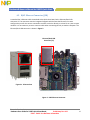
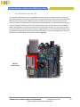
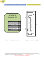
3.4. MicroSDCardSlot(J4)
ThemicroSDCardslotisusedastheprimarymeanstoboottheQuickStartboard.Thepowersourcefor
themicroSDCardslotisVLDO3_3V3.ThemicroSDCardslotisnotnormallyconfiguredwithacard
detectfeature.TheMicroSDCardslotcanbeconfiguredtobootfroma
MMCmicrocardwithan
alternatebootoptionsetting(seesectiononBootOptions).
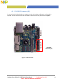
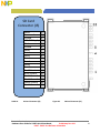
3.5. SDCardSlot(J5)
TheSDCardslotisa5‐in‐1SD/MMCcon nectorthatactsasasecondaryexternalmemorymediaslot.
ThepowersourcefortheSDCardSlotistheauxiliaryLDOregulator(DCDC_3V2).TheSDCardslotcan
beconfiguredasthebootsourcewithanalternatebootoption
setting,aswellasbeingconfiguredfor
eitherSDorMMCcardoperation(seesectiononBootOptions).TheSDCardSlotsupportsfull8‐bit
paralleldatatransfersandcansupportSDIOcards(WiFi,BT,etc)designedtofitinastandardSDcard
slot.TheQuickStartboardhas
specificallybeentestedwithanAtherosSD‐25WiFicard.
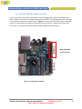
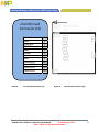
3.6. SATA7‐pinDataConnector(J7)
TheSATAconnectorprovid esthemeanstoconnectanexternalSATAmemorydevicetotheQuickStart
board.Commonly,thiswouldbeanExternalharddriveoraDVD/CDreader.PowerfortheSATAdevice
needstobesuppliede xternallybytheuserviaa12‐pinpowerconnector.It
ispossibletobootfroma
SATAdrivebymakingOTPfusechanges.Oncethefusechangesaremade,theycannotbereversed.
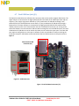
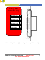
3.7. VGAVideoOutput(J8)
AstandardVGAsignalisoutputdirectlyfromthei.MX53Processorwithminimumexternalcomponents
required.PowerfortheTVEmoduleofthei.MX535ProcessorissuppliedbyVLDO7ofthePMICandis
setto2.75V.IfVGAoutputisnotdesired,itispossible toprogramthePMIC
toturnoffVLDO7to
conservepower.TheVGAoutputsupportsavarietyofvideoformatsupto150Mega‐Pixelspersecond.
LevelshiftersarerequiredontheHorizontalandVerticalSynchronizationsignalsaswellastheVGAI2C
communicationssignalsinordertomeetVGAspecifications.

Freescale Semiconductor
Hardware User Guide for i.MX53 Quick Start Board, Preliminary Rev 0.91 9
PUBI – Public Use Business Information
Hardware Reference Manual for i.MX53 Quick Start
3.8. LVDSVideoOutput(J9)
TheLVDSmoduleofthei.MX53Processorisconnectedtoa30‐pinLVDSconnector.Whilethei.MX53
ProcessoriscapableofoutputtingtotwoseparateLVDSdisplays,onlyoneconnectorispinnedouton
theQuickStartboard.ThepinoutsontheLVDSconnectormatchtheoptionalcable
and10”HannStar
LVDSdisplaythatcanbepurchasedoptionallyfromFreescale.ThesingleLVDSconnectorwillsupport
videoformatsupto165Mega‐Pixelspersecond.ThepowersourcefortheLVDSmoduleisaswitchable
outputoftheVBUCKPERIDCDCconverter.ThisrailissharedwiththeSATAmodule
andtheUSBmodule.
Ifthesemodulesarenotbeingused,thePMICcanbeprogrammedtoturnoffpowertothesethree
moduleswithoutaffectingother2.5Vsuppliestotheremainderofthei.MX53ApplicationsProcessor.
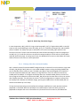
3.9. Ethernet(J2B)
Thei.MX53ProcessorFastEthernetModuleoutputsRMIIformattedsignalstoanexternalEthernetPHY.
Theprocessoriscapableof10/100Base‐Tspeeds.TheQuickStartboardusestheSMSCLAN8720A
EthernetTransceiverinaQFN‐24package.3.2V powerissuppliedtotheEthernetICfromtheexternal
LDOregulator.TheoutputoftheEthernetPHYis connectedtoanRJ45jackwithintegratedmagnetic.
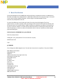
3.10. DualUSBHostConnector(J2A)
TheUSBmoduleofthei.MX53ProcessorprovidestwohighspeedUSBPHYsthatareconnectedtoeach
oftheUSB‐AHostJacksonconnectorJ2.OnePHYprovidesHost‐onlyfunctionalityandisconnectedto
theupperUSBjackontheconnectortower.ThesecondPHYisUSB
2.0OTGcapableandisconnectedto
thelowerUSBjackontheconnectortower.Bothja cksreceive5Vpowerdirectlyfromthe5VWall
PowerSupply,viaaFETthatcanbecontrolledbysoftware,anda1.1APoly‐fuse.ThePMICprovidesan
over‐voltagefunctionalitytolimitvoltage
appliedtotheUSBjackintheeventthataDCPowerSupply
otherthantheoriginalsupplyprovidedisused.Also,thereisnocurrentregulatingdevicetolimit
currentsuppliedtoeachjack,otherthanthePoly‐fuse.
NOTE
ThelowerUSBHostJackiscrossconnectedwith
theMicro‐BUSBDeviceconnector.Thiswasdoneasa
conveniencetotheuserascableswithmicro‐Aplugsarestilluncommonatthetimetheboardwas
designed.TheUSBOTGPHYwillswitchto‘device’modeifaUSBHostisattachedtothemicro‐B
connectorwithacable.Thisdesignisnotrecommendedforreleasetothegeneralelectronicsconsumer
population.ThisboardhasnotbeentestedforUSBcompliance.

Freescale Semiconductor
Hardware User Guide for i.MX53 Quick Start Board, Preliminary Rev 0.91 10
PUBI – Public Use Business Information
3.11. Micro‐BUSBDeviceConnector(J3)
Themicro‐BUSBconnectorisconnectedtotheUSBOTGPHYonthei.MX53Processer,andisalso
connectedtotheLowerUSBHostJackontheconnectortower.Theconnector’sexternalUSB5Vpower
pinisconnectedtotheUSB_OTG_IDpin,whichisnormallypulledtogroundvia
a3.3KOhmresistor.
WhenapoweredUSBHostdeviceisattachedtothemicro‐BUSBconnector,theUSB_OTG_IDpinis
pulledhighandsendsasignaltotheUSBOTGPHYtooperateindevicemode.Theconnector’sexternal
USB5VpowerpinisnotconnectedtothePMIC,
oranyotherpowerrailsontheQuickStartboard.
Therefore,itisnotpossibletosupplypowertotheQuick StartboardviatheUSBconnections.
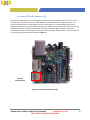
3.12. AudioInput/Output(J6/J18)
AnalogaudioinputandoutputareprovidedbyFreescale’sLowPowerStereoCodec,SGTL5000.The
audiocodecisconnectedtothei.MX53ApplicationsProcessorvia4‐wireI2Scommunications,utilizing
theAUDMUX5portoftheprocessor.Theaudiocodec’sHeadphoneAmpprovidesupto58mWoutput
to16‐Ohm
headphonesatatypicalSNRof98dBandTHD+Nof‐86dB.Typicalpowerconsumptionis
11.6mW.Inaddition,theaudiocodeccanperformseveralenhancementstotheoutputincludingvirtual
surround,addedbassandthreedifferenttypesofequalization.TheMicrophoneInputmoduleofthe
StereoCodecis
alsoused,withthemicrophoneinputconnectedtothetippinoftheMicrophoneJack
(J6).MicrophoneBiasvoltageisappliedontheQuickStartboardandnotasaseparateconnectionto
theMicrophone Jack.Iftheuserdesirestouseacombinedmicrophone,monoheadphonedevice,the
ferrite
beadonL25canbemovedtotheL22pads,redirectingtherightchan neloutputtothe
MicrophoneJack.A2.5mmto3.5mmadaptermaybenecessarytoconvertthemicrophone,mono
headphonedevicetofittheMicrophoneJack.OnboththeHeadphoneJackandMicrophonejack,a
fourthpinis
usedtodetecttheinsertionofaplugintoeitherjack.Whenastandard3‐pindeviceis
insertedintothe4‐pinjack,thedetectlineisgrounded,indicatingtothei.MX53Processorthattheplug
hasbeeninserted.
3.13. 5VPowerConnector(J1)
A2.0mmx6.5mmbarrelconnectorisusedwhichshouldfitstandardDCPlugswithaninnerdimension
of2.1mmandanouterdimensionof5.5mm.Ifanalternatepowersupplyisused(nottheoriginal,
suppliedpowersupply),itshouldsupplynomorethan5.25V/3Aoutput.If
thePMICsensestoohigh
voltageattheconnectorinput,itwillturnoffisolationFETQ1toprotecttheQuickStartboard.In
betweenthePowerConnectorandtheisolationFETisasingleblow,fastactingfusetoprotectthe
QuickStartboardfromanovercurrentsituationfault.
IfaWallPowerSupplyisproperlyconnectedto
theQuickStartboard,andthegreen5VpowerLEDindicatorisnotlit,itcouldmeanthateitherthefuse
hasbeenblown,orthatthevoltageoutputofthepo wersupplyistoohigh.

Freescale Semiconductor
Hardware User Guide for i.MX53 Quick Start Board, Preliminary Rev 0.91 11
PUBI – Public Use Business Information
Hardware Reference Manual for i.MX53 Quick Start
3.14. DebugUARTConnector(J16)
UART1ofthei.MX53ProcessorisconnectedtoanRS‐232outputtobeusedasadebugoutputforthe
developer.TheTransmit(TX)andReceive(RX)signalsaresentthroughtwo1.8Vto3.2Vlevelshiftersto
convertthelogicsignalvoltagestothecorrectvaluesforthe
SipexSP3232RS‐232transceiver.TheCTS
andRTSsignalsarenotusedontheQuickStartboard.TheRS‐232transceiverreceivesitspowerfrom
theexternal3.2VLDORegulator.Iftheoutputoftheregulatoristurnedoffforpowersavingsmeasures,
debugoutputwillbelost.
Ifthe
designerwishestousetheportasanApplicationsUARTPort,changescanbemadeinsoftwareto
reconfiguretheport.Amale‐to‐malegenderchangercanbeusedtoproperlyconverttheport.
Toaccessthedebugdataoutputduringdevelopment,connecttheDebugUARTConnectortoa
suitable
hostcomputerandopenaterminalemulationprogram(ie,TeratermorHyperTerminal).Propersettings
fortheterminalprogramare:
• BAUDRATE: 115,200
• DATA: 8bit
• PARITY: None
• STOPBIT: 1‐bit
• FLOWCONTROL: None
3.15. JTAGConnector(J15)
Astandard20‐pinARMJTAGconnectorisprovidedontheQuickStartboard.LogicsignalstotheJTAG
connectorare1.8Vsignals.A1.8Vreferencesignalisprovidedtopin1oftheconnectorsothatthe
attachedJTAGtoolcanautomaticallyconfigurethelogicsignalsfortheright
voltage.IftheJTAGtool
doesnothaveanautomaticlogicvoltagesense,makesurethatthetoolisconfiguredfor1.8V logic.
JTAGtoolsthathavebeenspecificallytestedwiththeQuickStartboardare:
• JTAGCommander(Macraigor)
• DS‐5andRealView(ARMLtd.)
• Trace32(Lauterbach)
• J‐Link(Segger/Codesourcery)
• J‐Link(IAR)

Freescale Semiconductor
Hardware User Guide for i.MX53 Quick Start Board, Preliminary Rev 0.91 12
PUBI – Public Use Business Information
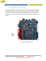
3.16. ExpansionHeader(J13)
A120‐pinExpansionPortHeaderisprovidedontheQuickStartboardforusewithmanyoptionally
expansionboardsavailablefromFreescale,orforcustomdesignedboardsmadebethedeveloper.At
thetimeofinitialproduction,thefollowingexpansionboardsareavailablefromFreescale:
• MCIMXHDMICARD HDMIsignal
outputdaughtercard
• MCIMX28LCD 4.3”WVGATouchPanelLCDDisplay
TheExpansionPortmakesthefollowingfeaturesofthei.MX53Processoravailabletobeusedona
custombuiltexpansioncard:
• TwoSerialPeripheralInterfaces(SPI) CSPI,eCSDPI2
• TwoI2S/SSI/AC97PortsAUDMUX4,AUDMUX5
• TwoInter‐Integrated
Circuits(I2C) I2C1,I2C2
• 2UARTsUAR T4,UART5
• SPDIFAudio
• USBULPIPortUSBH2
• 24‐bitDataanddisplaycontrolsignals
• ResistiveTouchScreenInterface
• VariousVoltagerails
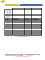
3.17. UserInterfaceButtons
Therearefour userinte rface buttonsontheQuickStartboard.Theirfunctionalityisasfollows:
POWER: Inthe‘PowerOff’state,momentarilypressingthePOWERbuttonwillbeginthePMIC
poweroncycle.ThePMICsuppliedvoltagerailswillcomeupinthepropersequenceto
powerthe
i.MX53Processor.Whentheprocessorisfullypowered,thebootcyclewillbe
initiated.
Inthe‘PowerOn’state,momentarilypressingthePOWERbuttonwillsendasignaltoa
GPIOportforuserdefinedaction,butwillnotinitiateahardwareshutdown.
Inthe‘PowerOn’state,holdingthe
powerbuttondownforgreaterthan5secondswill
resultinthePMICinitiatingashutdowntothe‘Standby’powercondition.Thiswillalso
betheresultfromthe‘PowerOff’stateasthePMICwilltransitionintothe‘PowerOn’
stateandwillstillseethePOWERbuttonasheld
down.
Page is loading ...
Page is loading ...
Page is loading ...
Page is loading ...
Page is loading ...
Page is loading ...
Page is loading ...
Page is loading ...
Page is loading ...
Page is loading ...
Page is loading ...
Page is loading ...
Page is loading ...
Page is loading ...
Page is loading ...
Page is loading ...
Page is loading ...
Page is loading ...
Page is loading ...
Page is loading ...
Page is loading ...
Page is loading ...
Page is loading ...
Page is loading ...
Page is loading ...
Page is loading ...
Page is loading ...
Page is loading ...
Page is loading ...
Page is loading ...
Page is loading ...
Page is loading ...
Page is loading ...
Page is loading ...
Page is loading ...
Page is loading ...
Page is loading ...
Page is loading ...
Page is loading ...
Page is loading ...
Page is loading ...
Page is loading ...
Page is loading ...
Page is loading ...
Page is loading ...
Page is loading ...
Page is loading ...
Page is loading ...
Page is loading ...
Page is loading ...
Page is loading ...
Page is loading ...
Page is loading ...
Page is loading ...
Page is loading ...
Page is loading ...
Page is loading ...
Page is loading ...
Page is loading ...
Page is loading ...
Page is loading ...
Page is loading ...
Page is loading ...
Page is loading ...
Page is loading ...
Page is loading ...
Page is loading ...
Page is loading ...
Page is loading ...
Page is loading ...
Page is loading ...
Page is loading ...
Page is loading ...
Page is loading ...
Page is loading ...
Page is loading ...
Page is loading ...
Page is loading ...
Page is loading ...
Page is loading ...
Page is loading ...
Page is loading ...
Page is loading ...
Page is loading ...
Page is loading ...
Page is loading ...
Page is loading ...
Page is loading ...
Page is loading ...
Page is loading ...
Page is loading ...
Page is loading ...
Page is loading ...
Page is loading ...
Page is loading ...
Page is loading ...
Page is loading ...
Page is loading ...
Page is loading ...
Page is loading ...
Page is loading ...
Page is loading ...
Page is loading ...
Page is loading ...
Page is loading ...
Page is loading ...
Page is loading ...
Page is loading ...
Page is loading ...
Page is loading ...
Page is loading ...
Page is loading ...
Page is loading ...
Page is loading ...
Page is loading ...
Page is loading ...
Page is loading ...
Page is loading ...
Page is loading ...
Page is loading ...
Page is loading ...
Page is loading ...
Page is loading ...
Page is loading ...
-
 1
1
-
 2
2
-
 3
3
-
 4
4
-
 5
5
-
 6
6
-
 7
7
-
 8
8
-
 9
9
-
 10
10
-
 11
11
-
 12
12
-
 13
13
-
 14
14
-
 15
15
-
 16
16
-
 17
17
-
 18
18
-
 19
19
-
 20
20
-
 21
21
-
 22
22
-
 23
23
-
 24
24
-
 25
25
-
 26
26
-
 27
27
-
 28
28
-
 29
29
-
 30
30
-
 31
31
-
 32
32
-
 33
33
-
 34
34
-
 35
35
-
 36
36
-
 37
37
-
 38
38
-
 39
39
-
 40
40
-
 41
41
-
 42
42
-
 43
43
-
 44
44
-
 45
45
-
 46
46
-
 47
47
-
 48
48
-
 49
49
-
 50
50
-
 51
51
-
 52
52
-
 53
53
-
 54
54
-
 55
55
-
 56
56
-
 57
57
-
 58
58
-
 59
59
-
 60
60
-
 61
61
-
 62
62
-
 63
63
-
 64
64
-
 65
65
-
 66
66
-
 67
67
-
 68
68
-
 69
69
-
 70
70
-
 71
71
-
 72
72
-
 73
73
-
 74
74
-
 75
75
-
 76
76
-
 77
77
-
 78
78
-
 79
79
-
 80
80
-
 81
81
-
 82
82
-
 83
83
-
 84
84
-
 85
85
-
 86
86
-
 87
87
-
 88
88
-
 89
89
-
 90
90
-
 91
91
-
 92
92
-
 93
93
-
 94
94
-
 95
95
-
 96
96
-
 97
97
-
 98
98
-
 99
99
-
 100
100
-
 101
101
-
 102
102
-
 103
103
-
 104
104
-
 105
105
-
 106
106
-
 107
107
-
 108
108
-
 109
109
-
 110
110
-
 111
111
-
 112
112
-
 113
113
-
 114
114
-
 115
115
-
 116
116
-
 117
117
-
 118
118
-
 119
119
-
 120
120
-
 121
121
-
 122
122
-
 123
123
-
 124
124
-
 125
125
-
 126
126
-
 127
127
-
 128
128
-
 129
129
-
 130
130
-
 131
131
-
 132
132
-
 133
133
-
 134
134
-
 135
135
-
 136
136
-
 137
137
-
 138
138
-
 139
139
-
 140
140
-
 141
141
-
 142
142
-
 143
143
-
 144
144


NXP i.MX537 Reference guide
- Category
- Server barebones
- Type
- Reference guide
Ask a question and I''ll find the answer in the document
Finding information in a document is now easier with AI
Related papers
Other documents
-
 T'nB ADAMUSB1 Datasheet
-
 DROK 2001708006 User manual
-
Freescale Semiconductor MCIMX53SMD Hardware User's Manual
-
Dahua SDZ4032-HNR-ZB User manual
-
-
GOCLEVER TI1010B Datasheet
-
-
Digi ConnectCore i.MX53 User manual
-
-
 ELENBERG CTV-1515 User manual


