Star 255B Operating instructions
- Category
- Cooker hoods
- Type
- Operating instructions
This manual is also suitable for

2M-Y3213 Rev. G 10/2/95
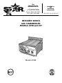
DESIGNER SERIES
GAS CHARBROILER
MODELS 255B and 257
Model 255B
Star
Manufacturing
International Inc.
10 Sunnen Drive
St. Louis, MO 63143
Phone: (800) 264-7827
FAX: (800) 264-6666
Installation
and
Operating
Instructions

This Star Designer Series Gas Broiler is
equipped for the type of gas indicated on
the nameplate mounted on the inside of
the door.
-IMPORTANT-
INSTALLATION: INSTALL IN NON-
COMBUSTIBLE LOCATIONS ONLY!
Clearance from non-combustible
construction must be 6" from back and
sides.
WARNING: Improper installation,
adjustment, alteration, service or
maintenance can cause property
damage, injury or death. Read the
installation, operating and maintenance
instructions thoroughly before installing
or servicing this equipment.
The installation of the appliance must
conform with the local codes, NATIONAL
FUEL GAS CODES "ANSI Z223.1 -
LATEST EDITION" AND ALL LOCAL GAS
COMPANY RULES AND REGULATIONS.
FOR YOUR SAFETY
DO NOT STORE OR USE GASOLINE OR
OTHER FLAMMABLE VAPORS AND
LIQUIDS IN THE VICINITY OF THIS OR
ANY OTHER APPLIANCE. KEEP THE
APPLIANCE AREA CLEAR AND FREE
FROM COMBUSTIBLES.
GENERAL INSTALLATION DATA
CAUTION
This equipment is designed and sold for
commercial use only by personnel
trained and experienced in its operation
and is not sold for consumer use in and
around the home nor for use directly by
the general public in food service
locations. For equipment to be used by
the general public, please contact the
factory.
This appliance, its pressure regulator
and its individual shutoff valve must be
disconnected from the gas supply piping
system during any pressure testing of
that system at test pressures in excess of
1/2 PSIG. This appliance and its
pressure regulator must be isolated from
the gas supply piping system by closing
its individual manual shutoff valve
during any pressure testing of the gas
supply piping system at test pressures
equal to or less than 1/2 PSIG. For your
protection, we recommend a qualified
installing agency install this appliance.
They should be familiar with gas
installations and your local gas
requirements. In any case, your gas
company should be called to approve the
final installation. In addition, there
should be posted, in a prominent
location, detailed instructions to be
followed in the event the operator smells
gas. Obtain the instructions from the
local gas supplier.
LEVELING UNIT
This broiler is supplied with 4 feet which
must be screwed into the legs attached
to the body. Level unit by adjusting the
4 feet which must have an adjustment of
1" for accurate and perfect line-up with
other Designer Series Units.
CAUTION
DO NOT INSTALL WITHOUT
ATTACHING THE FEET - DO NOT
REMOVE FEET.
GAS INPUT TO BROILER
90,000 BTU/HR total, or 15,000 BTU/
HR for one burner for Model 257. 60,000
BTU/HR total, or 15,000 BTU/HR for
one burner for Model 255B.

GAS PIPING
Gas piping shall be of such size and so
installed as to provide a supply of gas
sufficient to meet the full gas input of
the appliance. If the appliance is to be
connected to existing piping, it shall be
checked to determine if it has adequate
capacity. Joint compound (pipe dope)
shall be used sparingly and only on the
male threads of the pipe joints. Such
compounds shall be resistant to the
action of L.P. gases. WARNING: Any
loose dirt or metal particles which are
allowed to enter the gas lines on the
appliance will damage the automatic
valve and affect its operation. When
installing this appliance, all pipe and
fittings must be free from all internal
loose dirt.
PRESSURE REGULATOR
A convertible pressure regulator is
provided with each broiler. It should be
connected to the inlet pipe at the rear of
the unit. The gas supply line is then
connected to it. It is shipped set for 6"
W.C. manifold pressure for use on
natural gas. Allow 6" clearance from
back of unit to wall for servicing and
installation.
CONNECTING GAS SUPPLY LINE
The gas inlet of the broiler is sealed at
the factory to prevent entry of dirt. Do
not remove this seal until actual
connection is made to the gas supply
line.
MANUAL SHUT OFF VALVE
A manual shut off valve should be
installed upstream from the manifold
and within six feet of the broiler.
NATURAL/LP GAS
This broiler is equipped with fixed orifice
hoods and is shipped from the factory for
use on Natural Gas. To convert to LP gas,
install the black burner orifice hoods
supplied in cloth bag attached on or near
the front panel (See directions below).
"For natural gas when equipped with no.
52 drill size orifice."
"For LP gas when equipped with no. 56
drill size orifice."
"For your safety refer to installation
instructions for conversion procedure."
1.Remove grill, radiants and burners.
2.Remove the burner orifice hoods and
install the black orifice hoods supplied.
3.Replace the burners, radiants and grill.
4.Set manifold pressure to (10) inchwater
column. A 1/8" pipe plug on the burner
manifold can be removed for attaching a
pressure gauge. Remove the slotted
cover from the pressure regulator and
invert the plug. Replace the cover on
the regulator andthe manifold plug.
Regulator is now set at 10" W.C.
CHECKING FOR GAS LEAKS
Soap and water solution, or other material
acceptable for the purpose of locating gas
leaks shall be used. MATCHES,
CANDLES, FLAME OR OTHER SOURCES
OF IGNITION SHALL NOT BE USED FOR
THIS PURPOSE. Check entire piping
system for leaks.
PILOT LIGHTING INSTRUCTIONS
The broiler is equipped with (6) standing
pilots Model 257 and (4) on Model 255B
and should be lighted immediately after
the gas is turned on.
1.Turn the burner valve knobs to "OFF"
position. CAUTION: If gas valves have
been on and gas has escaped through
the burners, turn unit off and wait 5
minutes to clear gas.
2.Remove valve knobs by pulling off.
3.Open front door panel.
4.Light pilots with match, using match
holder furnished with unit.
SHUTTING DOWN INSTRUCTIONS
Turn the burner valve knobs to the off
position to turn burners off.

AIR INTAKES IN BOTTOM
Air for combustion enters from the
bottom of the unit. Do not obstruct this
area.
OPERATING INSTRUCTIONS
LIGHTING
When broiler is first lighted, it will
smoke until the preservation oils and
impurities are burned off. When it stops
smoking, it is ready to use.
BROILING
Turn valves on and pre-heat unit on "HI"
before attempting to broil. You will have
to experiment with the grill settings and
the valve settings for your particular
meat products. We recommend that you
set the grate at the full tilt position to
start with. This position allows the
grease to run down the rods into the
grease tray, reducing flare ups.
CAUTION
Hot fat that drips onto the radiants
causes some flare ups. Check water
pans frequently and add a sufficient
amount of water when necessary.
Hot water vapors rising from the
water pans and through the
combustion chamber, helps reduce
flare ups. Exercise care when using
your broiler.
TILTING THE GRILL
CAUTION
Charbroilers are hot! Never attempt
to change the grill position while
meat products are cooking. Flare
ups can occur unexpectedly. Turn
off charbroiler and allow the
charbroiler to cool.
PILOT LIGHT REGULATION
The pilot lights on this broiler have been
adjusted at the factory. However, due to
variations of gas pressure in different
locations, the pilot light flames may have
to be adjusted at installation location.
Adjust pilot light flames as small as
possible, but high enough to light
burner immediately when burner valve
is turned on high.
BURNER OPERATION
To ignite burners, turn burner valve
knob to "HI" position. There are (6)
burners for Model 257 and (4) for Model
255B, and each one is controlled by an
individual high-low, on-off valve. An
infinite number of broiling temperatures
may be obtained by turning the burner
valve knob to any position between high
and low.
BURNER ADJUSTMENT
1.Turn burner valve knob to "HI"
position.
2.Slowly decrease openings of air
shutters to give a soft blue flame
having luminous tips, then slowly
increase openings to a point where
the yellow tips disappear and a hard
blue flame is obtained.
3.Set the low adjustment to maintain
approximately 1/8" high flame by
turning the screws inside the valve
shafts when the knob is turned to low.
EXHAUST CANOPY
Open hearth broilers inherently create a
good deal of heat and smoke and should
be installed under an efficient exhaust
hood with flame proof filters. A vertical
distance of not less than 48" shall be
provided between the top of the
appliance and filters or any other
combustible material.
AIR SUPPLY
Provisions for adequate air supply must
be provided.

REPAIRS AND SERVICE
This appliance should only be repaired
or serviced by the factory or factory
authorized personnel. Contact the
factory or one of its representatives or a
local service company for service or
maintenance if required.
RETAIN THIS MANUAL FOR FUTURE
REFERENCE
Part No. 2M-Y3213 Rev. G 10/2/95
GREASE PAN
A grease pan is located at the front,
inside the water pan and can be
removed from the front for cleaning. This
pan should be checked and emptied
when necessary.
CAUTION
EXERCISE CARE IN HANDLING THE
GREASE PAN SINCE IT CONTAINS
HOT GREASE.
AIR INTAKES IN BOTTOM
Air for combustion enters from the
bottom of the unit. Do not obstruct this
area.
Raise or lower grill by lifting the rod, at
the back of the charbroiler, on which the
grill rests, by its handles and placing the
rod on the next step of the rod brackets.
Use potholders or gloves to reposition
the rod.
ADJUSTING HEAT PATTERN
The broiler has six (6) heat zones on
Model 257 and four (4) on Model 255B,
controlled by individual valves. It is
possible through this arrangement to
have a high heat or searing section,
while having a low heat finishing or
holding section. For the searing
operation, set the valves for the section
at a position of "HI" or close to it. For
holding or finishing, set the valves closer
to the "LOW" position on the dial. You
select the heat pattern you like, and set
the valves accordingly.
CLEANING
Clean regularly; remove grate sections to
sink for washing. Rods rotate for easy
scraping. Brush out carboned particles
from the radiant area. Remove and wash
water pan and grease trough. Wipe
exterior stainless surfaces with
detergent and a cloth. A non-abrasive
cleaner can be used on caked areas.
LOCKING STRIPS
Grease tight locking strips are available
to join this broiler to any other Designer
Series units to form a solid bank. Specify
which models are to be banked and their
order in the line up when ordering
strips.
WATER PAN
There are (2) water pans on Model 257
and (1) on Model 255B which are located
at the bottom of the unit, and are easily
removed from the front of the unit.
Water should be added to the water pans
and replaced as necessary. The water
pans help prevent flare ups and catch
any grease that drips past the radiants.


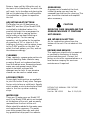
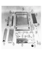
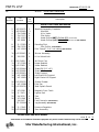
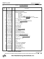
PARTS LIST EFFECTIVE 07-08-02 RB
8H MODEL 255B Gas Charbroiler
Key
Number
Part
Number
Number
Per
Unit
Description
IMPORTANT: WHEN ORDERING, SPECIFY VOLTAGE OR TYPE GAS DESIRED
INCLUDE MODEL AND SERIAL NUMBER
PAGE
1 OF 1
Some items are included for illustrative purposes only and in certain instances may not be available.
Star Manufacturing International, Inc.
Serial # 2552450 and ABOVE
2 H2-255072 1 Manifold Assembly Complete
3 H2-255065 1 Manifold
4 2V-Y2406 4 Hi-Lo Valve
5 2V-Y1177 4 Pilot Valve
6 G2-Y5357 4 Hood-Orifice (NAT) (Drilled #52) (for burner)
7 H2-3668 4 Hood-Orifices (LP) (Drilled #56) (for burner) (not shown)
8 2J-Y2391 4 Standing Pilot
8a 2A-Y1212 4 Pilot Orifice (not shown)
9 H2-Y2503 4 Pilot Tube (6”, 1/4” o.d. tubing) (not shown)
10 H2-255067 4 Burner Assembly
11 2R-9785 4 Hi-Lo Valve Knob
12 H2-Y2409 4 Air Mixer Cap
13 2F-Y2392 4 Upper Radiant
14 H2-Y2369 3 Lower Radiant
15 H2-255064 3 Grate (
20-7/8” x 8”)
16 H2-255082 1 Grate Lift Assembly
17 H2-255061 1 Grate Support
18 H2-Y2662 1 Left Grate Lift Support
19 H2-Y2661 1 Right Grate Lift Support
20 H2-255079 1 Grease Drawer
21 H2-Y2380 1 Drip Pan
22 H2-255078 1 Rear Splash Guard
23 2C-9788 2 Magnetic Door Catch
24 2J-7961 1 Lighter Rod
25 2A-7612 4 Foot
26 2C-9348 4 Stud
2A-9347 4 Foot Extension
(not shown)
Z1-115006 4 Leg Assembly (not shown)
28 2J-Y3947 1 Pressure Regulator
29 H2-255068 1 Door Assembly


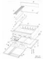
PARTS LIST EFFECTIVE 07-10-02 RB
8H MODEL 257 Gas Charbroiler
Key
Number
Part
Number
Number
Per
Unit
Description
IMPORTANT: WHEN ORDERING, SPECIFY VOLTAGE OR TYPE GAS DESIRED
INCLUDE MODEL AND SERIAL NUMBER
PAGE
1 OF 1
Some items are included for illustrative purposes only and in certain instances may not be available.
Star Manufacturing International, Inc.
1 H2-257003 1 Body Casing Assembly
2 H2-257015 1 Manifold Assembly Complete
3 H2-257010 1 Manifold
4 2V-Y2406 6 Hi-Lo Valve
5 2V-Y1177 6 Pilot Valve
6 G2-Y5357 6 Hood-Orifice (NAT) (
Drilled #52) (for burner)
7 H2-3668 6 Hood-Orifices (LP) (Drilled #56) (for burner) (not shown)
8 2J-Y2391 6 Standing Pilot
8a 2A-Y1212 6 Pilot Orifice
(not shown)
9 H2-Y2503 6 Pilot Tube (6”, 1/4” o.d. tubing) (not shown)
10 H2-255067 6 Burner Assembly
11 2R-9785 6 Hi-Lo Valve Knob
12 H2-Y2409 6 Air Mixer Cap
13 2F-Y2392 6 Upper Radiant
14 H2-Y2369 5 Lower Radiant
15 H2-257009 5 Grate (
21-5/8” x 6-3/8”)
16 H2-257011 1 Grate Lift Assembly
17 H2-257012 1 Grate Support
18 H2-Y2662 1 Left Grate Lift Support
19 H2-Y2661 1 Right Grate Lift Support
20 H2-Y2380 1 Drip Pan (
18-11/16” x 20-5/32”)
21 H2-255079 1 Grease Drawer
22 H2-257014 1 Small Water Pan (9-9/16” x 20-5/32”)
23 2C-9788 3 Magnetic Door Catch
24 2J-7961 1 Lighter Rod
25 2A-7612 4 Foot
26 2C-9348 4 Stud
2A-9347 4 Foot Extension
(not shown)
Z1-115006 4 Leg Assembly (not shown)
28 2J-Y3947 1 Pressure Regulator
29 H2-257001 1 Door Assembly
30 H2-257013 1 Rear Splash Guard
31 H2-257008 1 Bottom Frame Assembly
32 H2-257006 1 Liner Assembly
-
 1
1
-
 2
2
-
 3
3
-
 4
4
-
 5
5
-
 6
6
-
 7
7
-
 8
8
-
 9
9


Star 255B Operating instructions
- Category
- Cooker hoods
- Type
- Operating instructions
- This manual is also suitable for
Ask a question and I''ll find the answer in the document
Finding information in a document is now easier with AI
Related papers
-
Star 8136RCBA-1-2 Owner's manual
-
Star TMRC24 Owner's manual
-
Star Manufacturing 8160RCBA Installation And Operating Instructions Manual
-
Star LRB-48 User manual
-
Star Manufacturing 8024CB Operating instructions
-
Star Manufacturing 8H-6015CBC Operating instructions
-
-
Star Manufacturing STAR-MAX 6024CBB-LP Operating instructions
Other documents
-
Star Manufacturing 6048CBB Installation And Operating Instructions Manual
-
-
-
-
-
 Bakers Pride CH-6 XX-6 Owner's manual
-
 Bakers Pride CH-6 XX-6 Owner's manual
-
-
Globe C36CB-SR User manual
-
 Bakers Pride F, C, L Series Charbroiler Owner's manual


