Page is loading ...

1
®
®
®
®
CONVEYOR
OVEN
MODEL
UM3240
UM3255
Installation and
Operation
Instructions
2M-Z9045 Rev. D 6/26/2007
UM3255
UM3240

2
3
2
These symbols are intended to alert the user to the presence of
important operating and maintenance instructions in the manual
accompanying the appliance.
RETAIN THIS MANUAL FOR FUTURE REFERENCE
NOTICE
Using any part other than genuine Star factory supplied parts relieves the
manufacturer of all liability.
Star reserves the right to change specifi cations and product design without
notice. Such revisions do not entitle the buyer to corresponding changes,
improvements, additions or replacements for previously purchased
equipment.
Due to periodic changes in designs, methods, procedures, policies and
regulations, the specifi cations contained in this sheet are subject to change
without notice. While Star Manufacturing exercises good faith efforts to provide
information that is accurate, we are not responsible for errors or omissions
in information provided or conclusions reached as a result of using the
specifi cations. By using the information provided, the user assumes all risks in
connection with such use.
MAINTENANCE AND REPAIRS
Contact your local authorized service agent for service or required maintenance. Please record the model
number, serial number, voltage and purchase date in the area below and have it ready when you call to
ensure faster service.
SAFETY SYMBOL
Model No.
Serial No.
Voltage
Purchase Date
Business 8:00 am to 4:30 p.m. Central Standard Time
Hours:
Telephone: (800) 807-9054 Local (314) 781-2777
Fax: (800) 396-2677 Local (314) 781-2714
E-mail [email protected]
Website: www.star-mfg.com
The Star Service Help Desk
Authorized Service Agent
Reference the listing provided with the unit
or
for an updated listing go to:
Website: www.star-mfg.com
E-mail [email protected]
Telephone: (800) 807-9054 Local (314) 781-2777
Mailing Address: Star Manufacturing International Inc.
10 Sunnen Drive
St. Louis, MO 63143
U.S.A

1
CAUTION
CAUTION
AT, CH, CZ, DK, ES, FI,
GB, GR, HU, IE, IT, NO,
PT, SE
NL LU, DE BE, FR
GAS I2H I2L I2E I2E+
P
(mBAR)
G20 @ 20 G25 @ 25 G20 @ 20 G20 @ 20/25
Gas/Country Designations
IMPORTANT
POST, IN A PROMINENT LOCATION, THE EMERGENCY TELEPONE NUMBER OF YOU
LOCAL GAS SUPPLIER AND INSTRUCTIONS TO BE FOLLOWED IN THE EVENT YOU
SMELL GAS.
Instructions to be followed in the event you smell gas shall be obtained by consulting the local
gas supplier. If the smell of gas is detected, immediately call the emergency phone number of
your local gas company. There personnel and provisions available to correct the problem.
FOR YOUR SAFETY DO NOT STORE OR USE GASOLINE OR OTHER
FLAMMABLE VAPORS AND LIQUIDS IN THE VICINITY OF THIS OR ANY OTHER
APPLIANCE.
The installation of the Appliance must conform to the NATIONAL FUEL GAS CODE
"ANSI Z223.1 - LATEST EDITION" AND ALL LOCAL GAS COMPANY RULES AND
REGULATIONS.
IN CANADA INSTALLATION SHALL BE IN ACCORDANCE WITH THE CURRENT CAN/
CGA-B149.1 NATURAL GAS INSTALLATION CODE OR CAN/CGA-B149.2 PROPANE
INSTALLATION CODE AND LOCAL CODES WHERE APPLICABLE.
IMPROPER INSTALLATION, ADJUSTMENT, ALTERATION, SERVICE, OR
MAINTENANCE CAN CAUSE PROPERTY DAMAGE, INJURY, OR DEATH. READ
ALL INSTRUCTIONS THOROUGHLY BEFORE INSTALLING OR SERVICING THIS
EQUIPMENT.
IMPORTANT
An electrical wiring diagram for the oven is located on the inside cover of the
Control Box Top Lid.
NOTICE
THIS APPLIANCE SHALL BE INSTALLED IN CONFORMITY WITH CURRENT
REGULATIONS & USED ONLY IN A WELL VENTILATED LOCATION. CONSULT THE
INSTRUCTIONS BEFORE INSTALLING AND USING THE APPLIANCE.

2
TABLE OF CONTENTS
page
Important Warnings 1
Specifi cations 3
Oven Components 4
General Information 5
Purchaser’s Responsibilities 5
Important Safety Information 6
INSTALLATION INFORMATION 7
Location 7
Gas Supply Rating & Sizing 7
Access Considerations 7
Electrical Connection 8
IEC/CEE Equipotential Ground 8
Pressure Regulation 9
Pressure Testing 9
Ventilation 10
Smoke Candle Test 10
Base Pad Assembly 11
Oven to Base Assembly 11
Stacking Instructions 12
Conveyor Installation 13
Conveyor Belt Direction 14
Restraint Requirement 15
OPERATING INSTRUCTIONS
Safety Operating Instructions 16
Operation 16
Turn Unit On 17
Adjusting Time & Temp 17
Shut Down Procedures 17
DISPLAY INFORMATION
Store Level 18
Manger Level 18
Additional Functions 18
Error Codes 18
Bake Time versus Temp 19
Conveyor Speed 19
Time of Delivery 19
MAINTENANCE INSTRUCTIONS
Daily, Monthly, 3 Months, Annually 20-21
Nozzle Finger Assembly / Dissembly 21
Conveyor Belt Tension 22
Conveyor Belt Link Removal 22
Wiring Diagram 23
EXPLODED VIEW & PARTS LIST
Front Panel Assembly 24-25
Rear Panel Assembly 26-27
Conveyor Assembly 28-29
Control Box Assembly 30-31
Control Box Door Assembly 32-33
Manifold & Blower/Burner Assembly 34-35
Warranty 36
®
UM3240 - UM3255 CONVEYOR OVEN

3
SPECIFICATIONS
UM3240-NAT, UM3240-LP
Gas Rating/Connection: 120,000 BTU/hr (504 kcal/min)
3/4" NPT female pipe connection (BSP adapter supplied on CE models)
Gas Supply Pressure: Natural - 5-6" water column (15-30 mBar) @ rated fl ow
Propane - 11-12" water column (27.5-30 mBar) @ rated fl ow
Electrical Supply: Separate 15 Amp 208-240VAC, single phase, 50/60 Hz service per Oven
Approximate Weight (Single Oven without base): Shipping - 868 Lbs (393.7 kg)
(Single/Double Base): Shipping - 177.3 Lbs (80.4 kg)
(Triple Base): Shipping - 188.3 Lbs (85.4 kg)
(Fingers): Shipping - 91.5 Lbs (41.5 kg)
(Single Oven with base): Installed - 717 Lbs (325.2 kg)
(Double Oven with base): Installed - 1292 Lbs (586 kg)
(Triple Oven with base): Installed - 1878 Lbs (851.8 kg)
Dimensions: Width: 80.2" (203.7 cm) - w/control panel door closed
96.2" (244.3 cm) - w/control panel door open
Depth: 60.5" (153.7 cm) - Front Door(s) Closed
102.9" (261.4 cm) - Front Door(s) Open
Height: 43.1" (109.5 cm) - Single Oven with Stand
61.1" (155.2 cm) - Double Oven with Stand
63.5" (161.4 cm) - Triple Oven with Dolly
Recommended Minimum Clearances:
Rear of Oven to Wall 0" (0 cm)
Conveyor Extensions to Wall 6" (0 cm)
Allowing 16.25" on the control panel door to open will allow for easier service
UM3255-NAT, UM3255-LP
Gas Rating/Connection: 150,000 BTU/hr (630 kcal/min)
3/4" NPT male pipe connection (BSP adapter supplied on CE models)
Gas Supply Pressure: Natural - 5-6" water column (15-30 mBar) @ rated fl ow
Propane - 11-12" water column (27.5-30 mBar) @ rated fl ow
Electrical Supply: Separate 15 Amp 208-240VAC, single phase, 50/60 Hz service per Oven
Approximate Weight (Single Oven without base): Shipping - 922 Lbs (418.2 kg)
(Single/Double Base): Shipping - 205.3 Lbs (93.1 kg)
(Triple Base): Shipping - 216.3 Lbs (98.1 kg)
(Fingers): Shipping - 122 Lbs 55.3 kg)
(Single Oven with base): Installed - 827 Lbs (375.1 kg)
(Double Oven with base): Installed - 1484 Lbs (673.1 kg)
(Triple Oven with base): Installed - 2152 Lbs (976.1 kg)
Dimensions: Width: 94.6" (240.3 cm) - w/control panel door closed
110.6" (280.9 cm) - w/control panel door open
Depth: 60.5" (153.7 cm) - Front Door(s) Closed
102.9" (261.4 cm) - Front Door(s) Open
Height: 43.1" (109.5 cm) - Single Oven with Stand
61.1" (155.2 cm) - Double Oven with Stand
63.5" (161.4 cm) - Triple Oven with Dolly
Recommended Minimum Clearances:
Rear of Oven to Wall 0" (0 cm)
Conveyor Extensions to Wall 6" (0 cm)
Allowing 16.25" on the control panel door to open will allow for easier service

4
IL1173
A
B
C
D
E
F
G
H
H
I
J
VIEW A
VIEW A
K
L
M
N
O
I
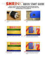
OVEN COMPONETS DESCRIPTION
A: Conveyor Belt: Moves the product through the oven
B: Conveyor Assembly: Supports the Conveyor Belt, the
ends fold up for easy removal.
C: Control Panel: Bright Red Display for easy notifi cation
of ovens current operation, and buttons for making quick
modifi cations.
D: Air Intake: Located on the end of the control box to pre-
vent the electronic controls from overheating as well as
to allow for a more direct air fl ow into the blowers. DO
NOT BLOCK these air intakes and wipe them clean on a
regular basis.
E: Machinery Compartment Access Door: Allows access
to the oven’s interior Finger components.
F: Access Window: This allows easy access to the cooking chamber, for product to be placed in to give
a shorter or additional cooking time to the product.
G: Heat Shutter: Can be adjusted to various settings, depending on product being placed in the oven, to
prevent heat loss
H: Crumb Tray: Catches crumbs and other material that drops through the conveyor belt. Located at
each end of the conveyor assembly.
I: Conveyor End & Side Stops: Prevents product from falling off of the moving conveyor.
J: Fingers: Projects streams of hot air onto the product.
K: Circuit Breaker 10Amp: Protects components from over amperage.
L: Hi-Limit Reset: Monitors inside cooking temperature and will only trip when unitended temperature is
reached.
M: Nameplate: Has specifi c information regaring this units electrical & gas requirements as well as the
units serial number which is needed for any service that will be required. This number should be written
in the inside cover of this manual and kept for future needs
N: Electrical Input: Electrical Supply connection must meet all national and local electrical code
requiremtns.
O: Gas Connection: The installation must confi rm with local codes or in the absence of local codes, with
the National Fuel Gas Code, ANSI Z2223.1 latest edition.
OVEN COMPONENTS

5
GENERAL INFORMATION
This equipment is designed and sold for commercial use only by personnel trained and experienced
in its operation and is not sold for consumer use in and around the home nor for use directly by
the general public in food service locations.
Before using your new equipment, read and understand all the instructions & labels
associated with the unit prior to putting it into operation. Make sure all people associated
with its use understand the units operation & safety before they use the unit.
First and foremost, each crate should be examined before signing the Bill of Lading to report any
visible damage by the freight carrier in transit and to account for the proper number of crates.
If there is apparent damage, arrangements should be made to fi le a claim against the carrier
within 15 days. Interstate Commerce Regulations require that the claim must be initiated by the
consignee. Proper and secure storage facilities should be arranged for the oven(s) if necessary
to protect it from outdoor or damp conditions at all times before installation.
-IMPORTANT-
When you have all the crates unloaded, open the crates and remove all plastic covers. Inspect
at once for concealed damage. If anything appears to be damaged, contact the appropriate
persons immediately to fi le a damage claim. After completing this inspection, fi nish unpacking
the oven. Be sure to remove all paper protection and packing material from the unit prior
to lighting.
NOTICE
This appliance must be installed with a stand and casters designed by Star Manufacturing as part
of a complete installation. The installation must also include a connector complying with either
ANSI Z21.69 or CAN/CGA-6.16 and a quick-disconnect device complying with either ANSI Z21.41
or CAN1-6.9. It must also be installed with restraining means to guard against transmission of
strain to the connector as specifi ed in the appliance manufacturer's instructions.
For your protection, we recommend a qualifi ed installing agency install this appliance. They
should be familiar with gas installations and your local gas requirements. In any case, your gas
company should be called to approve the fi nal installation.
This appliance, its pressure regulator, and its individual shutoff valve must be disconnected
from the gas supply piping system during any pressure testing of that system at test pressures
in excess of 1/2 PSIG. This appliance and its pressure regulator must be isolated from the gas
supply piping system by closing its individual manual shutoff valve during any pressure testing
of the gas supply piping system at test pressures equal to or less than 1/2 PSIG.
PURCHASER'S RESPONSIBILITY
It is the responsibility of the purchaser:
1. To see that the gas and electric services for the oven are installed on site in accordance
with the manufacturer's specifi cations and municipal codes.
2. To see that all gas and electric services are connected properly by a qualifi ed installer of your
choice. All such connections must be in accordance with applicable code requirements.
3. To arrange for inspection and operation check-out by an authorized service technician.
The warranty becomes effective upon verifi cation of proper installation.

6
IMPORTANT SAFETY INFORMATION
Do not attempt to operate the oven until connection of utility service has been fully inspected
by an authorized service technician or a Star Service Representative. This service is required
by Star in order to assist the purchaser in proper start-up of the oven on site. Please note
the specifi c details on the Warranty and make certain that service connections are made to
proper utility services.
The warranty shall not apply if the oven is started up and operated prior to the utilities and
oven being inspected and check-out made by an authorized service technician or a Star
Service Representative.
IMPROPER INSTALLATION, ADJUSTMENT, ALTERATION, SERVICE, OR
MAINTENANCE CAN CAUSE PROPERTY DAMAGE, INJURY, OR DEATH. READ
ALL INSTRUCTIONS THOROUGHLY BEFORE INSTALLING OR SERVICING THIS
EQUIPMENT.
Post in a prominent location the emergency telephone number of your local
gas supplier and instructions to be followed in the event you smell gas. If the
smell of gas is detected, immediately call the emergency phone number of
your local gas company. They will have personnel and provisions available to
correct the problem.
It is required that the oven be placed under a ventilation hood to provide for
adequate air supply and ventilation.
Minimum clearances must be maintained from all walls and combustible
materials. Minimum clearances for this unit should be 0 inches from the rear
and 6 inches from both sides. Keep the oven free and clear of all combustible
material, for use only on Non-Combustable fl oors.
Adequate clearance for air openings to the combustion control chamber on the
right side of the oven is required. Do not obstruct the ventilation holes in the
control panels as these provide the combustion air for the burner and cooling
air for the controls.
The oven is to be operated only on the type of gas and electricity shown on the
specifi cation plate. The burner will not operate and gas will not fl ow through
the burner without electric power.
If the supply cord is damaged, it must be replaced by the manufacture,
its service agent or similarly qualifi ed persons in order to avoid a hazard.
Star replacement parts are listed in the parts list section of this manual.
CAUTION
CAUTION
CAUTION
CAUTION
CAUTION
CAUTION
WARNING

7
INSTALLATION INFORMATION
THE INSTALLATION INSTRUCTIONS CONTAINED HEREIN ARE FOR THE USE OF
QUALIFIED INSTALLATION AND SERVICE PERSONNEL ONLY. INSTALLATION OR
SERVICE BY OTHER THAN QUALIFIED PERSONNEL MAY RESULT IN DAMAGE TO THE
OVEN AND/OR INJURY TO THE OPERATOR.
Qualifi ed installation personnel are individuals, a fi rm, a corporation, or a company which either
in person or through a representative are engaged in and responsible for:
1. The installation or replacement of gas piping and the connection, installation, repair, or
servicing of equipment.
2. The installation of electrical wiring from the electric meter, main control box, or service outlet
to the electric appliance.
Qualifi ed installation personnel must be experienced in such work, familiar with all precautions
required, and have complied with all requirements of state or local authorities having
jurisdiction.
LOCATION
The well-planned and proper placement of your oven will result in long-term operator convenience
and satisfactory performance.
NOTE: On gas conveyor ovens, routine servicing can usually be accomplished within the limited
movement provided by the gas hose restraint. If the oven needs to be moved further from the
wall, the gas must fi rst be turned off and disconnected from the oven before removing the restraint.
Reconnect the restraint after the oven has been returned to its regular position.
It is essential that an adequate air supply to the oven be maintained to provide a suffi cient fl ow
of combustion and ventilation air. Follow these guidelines:
1. Place the oven in an area that is free of drafts.
2. Keep the oven area free and clear of all combustibles such as paper, cardboard, fl ammable
liquids, and solvents. Oven should only be used on Non-Combustible Floors.
3. Do not place the oven on a curb base or seal to a wall. This will restrict the fl ow of air and
prevent proper ventilation to the blower motors. This condition must be corrected to prevent
permanent damage to the oven.
4. On all models, tripping of the blower motor's thermal overload device indicates an excessive
ambient temperature at the back of the oven. This condition must be corrected to avoid
permanent damage to the oven.
GAS SUPPLY RATING AND SIZING
Calculations for pipe sizing must take into account the maximum usage rate of all other appliances
in the kitchen or one or more of the appliances will suffer from inadequate or dangerous
performance. The 3/4" NPT connection for the oven is generously sized for use in the control
box of the oven. However, unless the oven installation is within 10 feet of the main building gas
supply, the supply must be larger. For each oven, a 3/4" NPT fl exible quick connect hose and
full port gas shut-off valve is recommended as a MINIMUM. The main pipe supplying each oven
branch may need to be larger depending on the number of appliances serviced, the number
of elbows in the piping, and the pressure. This should be sized and installed by a professional
familiar with any local codes that may also affect the installation.
ACCESS CONSIDERATIONS
Locating the gas valve(s), quick connect hose(s) and electrical outlet(s) at the control box end
of the oven will allow easier access for any service visits. This improved access should make
any necessary service quicker resulting in less kitchen disruption. It will also allow easier
disconnection of electricity, gas, and restraints for cleaning around and behind the oven.
UTILITY INSTALLATION

8
ELECTRICAL CONNECTION
Before making any electrical connections to this unit, check that the power supply is adequate
for the voltage, amperage, and phase requirements stated on the rating plate. A wiring diagram
is included herewith.
ENSURE THAT BOTH THE CIRCUIT BREAKER AND THE POWER (ON/OFF) SWITCH
IS IN THE OFF POSITION BEFORE PROCEEDING.
BE CERTIAN THAT ALL PACKING MATERIAL HAS BEEN REMOVED FROM INSIDE
THE OVEN'S CHAMBER.
When installed, this appliance must be electrically grounded and its installation must comply with
the National Electric Code, ANSI-NFPA 70, latest version, manufacturer's installation instructions,
and applicable local municipal building codes. In Canada, all electrical connections are to be in
accordance with CSA C22.1 - Canadian Electrical Code Part 1 and/or local codes.
This device is equipped with a 3-prong (grounded) plug for your protection against shock
hazard and should be plugged directly into a properly grounded three prong receptacle.
DO NOT cut or remove the grounded prong from this plug.
EQUIPOTENTIAL GROUNDING - CE ONLY
On CE units, connect an equipotental ground wire to the ground lug shown in the fi gure below.
The equipotential ground connection must meet current IEC/CEE and local code requirements.
The ground lug is found on the rear side of the control box, below the equipotential ground
symbol.
On certain CE/UK models install the IEC plug using the cord holder provided.
UTILITY INSTALLATION
WARNING
Equipotential
Ground Lug
Cord Holder
IEC Plug
IL1242
Symbol
IEC/CEE Equipotential Ground Connection
WARNING
CAUTION

9
PRESSURE READING
TEST NIPPLE
IL1191
SET-SCREW
GAS PRESSURE
ADJUSTMENT SCREW
IS UNDER CAP
OVEN MANIFOLD PRESSURE REGULATION
Each oven has been adjusted at the factory to operate with
the gas specifi ed on the nameplate.
Each oven is supplied with a regulator to maintain the proper
gas pressure. The regulator is essential to the proper
operation of the oven and should not be removed or replaced
by another model unless approved by Star Manufacturing.
A pressure reading can be taken at the test nipple provided.
You must back the set-screw one turn for this test, be certain
to re-tighten when you are done. Failure to reset the set-
screw to its original position will create a gas leak once the
unit is back in operation. The reading should be taken while
the oven is heating up & at high fi re. The regulator is located
on the bottom of the gas combination valve, just inside the
control box. Adjust gas manifold regulator gas pressure by
removing the cap and adjusting the regulator adjustment
screw to match the pressure listed on the name plate (3.5"
Nat, 4.8" Propane). Clockwise to increase, counterclockwise
to decrease.
Oven Manifold Regulator, w/Set Screw
PRESSURE TESTING GAS SUPPLY LINE
During pressure testing note the following:
1. The oven and its individual manual shut-off valve must be disconnected from the gas supply piping
system during any pressure testing of that system at test pressures in excess of 1/2 psig (3.45 kPa).
Turn OFF main gas shut-off valve or main gas supply line.
2. The oven must be isolated from the gas supply piping system by closing its individual manual shut-
off valve during any pressure testing of the gas supply piping system at test pressures equal to or
less than 1/2 psig (3.45 kPa).
3. If incoming pressure is over 14" water column, a separate regulator for the oven must be installed
before the gas supply to the oven.
To prevent damage to the control valve regulator during the initial turn-on of
gas, it is very important to open the manual shut-off valve very slowly. After the
initial gas turn-on, the manual shut-off valve must remain open except during
pressure testing as outlined in the above steps or when necessary during service
maintenance.
NOTE: The supplied regulator is evaluated for a maximum gas supply pressure of
14" water column (34.5 mBar). The recommended maximum gas supply pressure
is 12" water column (29.9 mBar).
Installation must conform with local codes or, in the absence of local codes, with the National
Fuel Gas Code, NFPA54/ANSI Z223.1 - Latest Edition, the Natural Gas Installation Code
CAN/CGA-B149.1 or the Propane Installation Code CAN/CGA-B149.2 as applicable.
UTILITY INSTALLATION
CAUTION
WARNING

10
VENTILATION
A VENT IS REQUIRED: Local codes prevail. These are the "authority having
jurisdiction" as stated by the National Fire Protection Association, Inc. in NFPA
96-Latest Edition. For further ventilation information see below.
A ventilation hood is required to remove heat and cooking odors. For gas ovens, a ventilation
hood is also required to remove the products of combustion. The hood and HVAC installation
must meet local codes to gain approval by the authority having jurisdiction. Requirements may
vary depending on the location by city, county, and state. Obtain information from the authority
having jurisdiction to determine the requirements for your installation. Obtain information and
review copies of codes or documents that will be used to inspect and approve your installation.
Your ventilation hood supplier and HVAC contractor should be contacted to provide guidance. A
properly engineered and installed ventilation hood and HVAC system will expedite approval and
reduce oven maintenance costs. Proper ventilation is the responsibility of the oven's owner.
The ventilation hood must operate in harmony with the building HVAC system. (The effi ciency
of various hood designs makes it necessary to specify such a wide range of ventilator CFM.)
Make-up air must be supplied by either a hood design or the HVAC system to avoid a negative
pressure condition. This will vary with hoods from various manufacturers. Air supplied directly
from outside the building to the kitchen or oven area, non-tempered, could be used as supply
air but the design would have to accommodate potential operational changes.
IL1177
RIGHT SIDE FRONT SIDE
VENTILATION
CAPTURE AREA
VENTILATION
CAPTURE AREA
CAUTION
Prevent airfl ow through the cooking
tunnel. Air must NOT be directed onto
the oven's front or rear or to the sides
of the cooking area.
The following drawing shows a typical
installation and is intended to be a guideline.
This is not a rigid specification. Hood
dimensions and positioning over the oven
will vary with hood manufacturer & local
guidelines.
Damage sustained as a direct result of
improper ventilation will not be covered by
the warranty.
Failure to properly vent the oven can be hazardous to the health of the operator
and may result in operational problems, unsatisfactory baking, and possible
damage to the equipment.
SMOKE CANDLE TEST
In order to verify the proper function of your ventilation system, a smoke candle test should
be done. If testing a multiple oven system, this test should be done on the bottom oven. The
conveyor coupling should be disconnected so conveyor does not move and the oven temperature
must be set and operating at a minimum of 480°F (249°C).
Test Procedure:
CAUTION
1. Wear heat-resistant gloves to prevent burns.
2. Put the smoke candle in an cake pan.
3. Insert candle through conveyor tunnel or oven
door. (Use Star Smoke Candle 2W-Z5668.)
4. Light the fuse of the smoke candle and
immediately center the pan in the oven cavity on
the conveyor belt (keeping the oven door and
window closed).
5. Observe the smoke pattern coming out of
all oven openings and the collection of this
smoke by the ventilation system.
6. All smoke from the oven must be captured
by the ventilation system.
INSTALLATION VENTILATION

11
INSTALLATION OVEN ASSEMBLY
IL1174
Adj. Foot
Base
Oven
Top Panel Front
Top Panel Rear
Alignment
Studs
Alignment
Holes
Screw
DETAIL
A
Caster
Adj. Foot
Triple Stack Plate
Plate Cover
Bottom Leg Plate
Support Leg
Adj. Foot
Caster
IL1176
CASTERS for TRIPLE OVEN
CASTERS for SINGLE & DOUBLE OVEN
BASE PAD ASSEMBLY
Triple Stack Applications
1. Bolt the caster assembly to the Bottom
Leg Plate & Plate Cover using provided
hardware.
2. Screw the Foot Assembly in place as
shown.
3. Bolt the Bottom plate assembly to each
corner of the Base Pad Assy. using provided
hardware.
4. With assistance turn the Base Pad upright.
Single & Double Stack Applications
1. Install the support legs in position in each
corner of the Base Pad Assy. using provided
hardware.
2. Bolt the caster assembly to the Bottom Leg
Plate using provided hardware.
3. Screw the Foot Assembly in place as
shown.
4. Bolt the Bottom plate assembly to the
Support Leg securing with the washer & nuts
provided.
5. With assistance turn the Base Pad upright.
OVEN TO BASE ASSEMBLY
1. Remove any packaging material that was
shipped with the oven and base.
2. Prior to placing the oven onto the base
make sure the base insulation material is
positioned correctly.
3. With assistance, lift the oven and position it
onto the base.
4. For Dual or Triple Oven Installations,
go directly to STACKING INSTRUCTION.
5. Install the Top Panels on top of the oven
making sure to line-up the Alignment Holes
with their appropriate Alignment Holes, as
shown here. See Detail A.
6. Secure the Top Panels in place.
7. Roll the Oven into position, using a level
adjust the Feet until oven is level.
Top Rear Panel Top Front Panel
Alignment Stud
Front
IL1205
DETAIL A

12
INSTALLATION OVEN ASSEMBLY
Oven
Oven
Top Panel Front
Top Panel Rear
Alignment
Studs
Alignment
Holes
Base
IL1175
Adj. Feet
Screw
Screw
Stacking Corners
Insulation
Insulation
Insulation
DETAIL A
STACKING INSTRUCTIONS
1. Remove any packaging material
that was shipped with the oven
and base.
2. Prior to placing the oven onto
the base make sure the base
insulation material is positioned
correctly.
3. With assistance, lift the oven and
position it onto the base.
4. Install the Stacking Corners, as
shown being sure to secure the
two rear with a screw.
5. Using an Oven Lift (see Pre-
Install Manual for specifi c Oven
Lifting Instructions) carefully
place the upper oven on top of
the lower oven. Note: Be careful
not to lift the unit by the Control
Box Assembly.
6. Be certain the insulation is
properly positioned.
7. Repeat steps 4 - 6 if for Triple
Oven Installations.
8. Install the Top Panels on top of
the oven making sure to line-up
the Alignment Holes with their
appropriate Alignment Studs, as
shown here. See Detail A.
9. Secure the Top Panels in place.
10. Roll the Oven into position, using
a level adjust the Feet until oven
is level.
Top Rear Panel Top Front Panel
Alignment Stud
Front
IL1205
DETAIL A

13
INSTALLATION OVEN ASSEMBLY
CONVEYOR INSTALLATION
Conveyor installation can only be installed from the control panel/drive motor side. This needs
to be removed when cleaning the cooking chamber and removing the Nozzel Finger Assembly
for disassembly & cleaning.
ALLOW THE OVEN TO COOL BEFORE INSTALLING OR REMOVING THE CONVEYOR
ASSEMBLY.
1. With Nozzel Finger Assemblies in position, place the Conveyor Guides on its mounting
studs located at the opening at each end of the cooking chamber.
2. Open the conveyor assembly, pull on the conveyor belt making sure it moves freely
without obstruction.
3. With assistance, lift the conveyor and slide it along the Conveyor Guides into position from
the drive motor side, be certain the crumb tray brackets are on the outside of the oven,
and the Drive Collar is on the control panel side as shown below.
4. Once the conveyor assembly is installed, slide the Drive Collar over the Drive Cog to sync
the conveyor with the drive motor.
Drive Collar
Drive Cog
IL1185
IL1186
Conveyor Belt
not shown
Crumb Tray
Bracket
Conveyor
Guide
Conveyor
CAUTION

14
INSTALLATION OVEN ASSEMBLY
CONVEYOR BELT DIRECTION
Conveyor travel is factory set for left to right operation. If the opposite direction is required, the
polarity of the drive motor must be reversed.
To reverse polarity:
1. DISCONNECT THE POWER CORD FROM THE UNIT.
2. Open the Control Box Door and swing open.
3. Find the Drive Motor and follow the wires back until you fi nd the connector shown
below.
4. Pressing your small screw driver, into the square hole on top of the connector, you
will be able to remove & reverse the black & brown wires of the connector on the
DRIVE MOTOR SIDE ONLY.
5. Close the Control Box Door, and secure with hardware.
6. Reconnect the unit to its electrical power source, and test for proper conveyor belt
direction change.
Wiring
Harness
Drive
Motor
(FACTORY PRESET)
LEFT TO RIGHT
CONVEYOR BELT DIRECTION
RIGHT TO LEFT
CONVEYOR BELT DIRECTION
IL1183
Screwdriver
Access Holes
Grey
Red
White
Yellow
Black
Brown
Grey
Red
White
Yellow
Wiring
Harness
Drive
Motor
Black
Brown
Brown
Grey
Red
White
Yellow
Black
Brown
Grey
Red
White
Yellow
Black

15
RESTRAINT REQUIREMENT
1. The installation shall be made with a gas connector that complies with local codes for
connectors for movable gas appliances and a quick-disconnect device that complies
with local codes for such devices in use with gas fuel.
NOTE: Because the oven is equipped with casters, the gas line connection shall be made
with a connector that complies with the Standard for Connectors for Movable Gas Appliances,
ANSI Z21.69 • CSA 6.16, and a quick-disconnect device that complies with the Standard for
Quick-Disconnect Devices for Use With Gas Fuel, ANSI Z21.41 • CAN1-6.9.
2. The installation of the restraint must limit the movement of the oven(s) without
depending on the connector, the quick disconnect device, or associated piping to
limit the oven movement.
3. If the restraint must be disconnected during maintenance or cleaning, it must be
reconnected after the oven has been returned to its originally installed position.
WALL STUD OR
MASONRY WALL
Eyebolt
Eyebolt
Restraining Kit
IL1187
INSTALLATION RESTRAINT

16
OPERATION
OPERATING INSTRUCTIONS
DO NOT ATTEMPT TO OPERATE THE OVEN until connection of utility service and installation
has been fully inspected (start-up check-out) by an authorized service technician or a Star Service
Technician in order to assure the oven is properly installed and in working order. The warranty
becomes effective upon verifi cation of proper installation.
DO NOT WORK AROUND THE CONVEYOR BELT WITH LONG HAIR, LOOSE
CLOTHING, OR DANGLING JEWELRY. GETTING CAUGHT IN THE BELT COULD
RESULT IN DISMEMBERMENT OR FATAL INJURY.
Unless specifi ed otherwise, conveyor travel is factory set for left to right operation when facing
the front of the oven. If a direction change is required, refer to "CONVEYOR BELT DIRECTION,"
for instructions on how to accomplish a belt direction change.
SAFETY OPERATING INSTRUCTIONS
The information contained in this section is provided for the use of qualifi ed operating personnel.
Qualifi ed operating personnel are those who have carefully read the information contained in this
manual, are familiar with the functions of the oven and/or have had previous experience with the
operation of the equipment described. Adherence to the procedures recommended herein will
assure the achievement of optimum performance and long, trouble-free service. Please take
time to read the following safety operating instructions. They are the key to the successful
operation of your Ultra-Max Conveyor Oven.
SAFETY TIPS
For your safety, read before operating.
If you smell gas:
1. DO NOT try to light any appliance.
2. DO NOT touch any electrical switches.
3. Use an exterior phone to call your gas supplier immediately.
4. If you cannot reach your gas supplier, call the fi re department.
In the event of a power failure:
1. Turn all switches off.
2. DO NOT attempt to operate the oven until the power is restored.
NOTE: In the event of a shut-down of any kind, allow a fi ve (5) minute shut-off
period before attempting to restart the oven.
General Safety Tips:
1. DO NOT use tools to turn off the gas control. If the gas cannot be turned off manually do
not try to repair it. Call a qualifi ed service technician.
2. If the oven needs to be moved for any reason, the gas must be turned off and disconnected
from the unit before moving the restraint cable. Reconnect the restraint after the oven has
been returned to its original location.
3. DO NOT remove the control box cover unless the oven is unplugged.
CAUTION

17
OPERATION
To turn the oven on:
1. Push the power switch to "ON."
2. If the burner does not light in one minute, push the power switch to the "OFF" position and
wait fi ve minutes.
3. After fi ve minutes, retry.
To adjust the time and temperature:
1. Press the DOWN and UP arrows ( ) at the same time. Hold for four seconds until the
TIME display goes blank.
2. Press the ENTER button (
) to switch between TIME and TEMPERATURE.
3. Press the UP arrow (
) to increase or the DOWN arrow ( ) to decrease the TIME or
TEMPERATURE. Hold either button down for faster display changes.
4. After fi ve seconds, the new numbers will be saved and the oven will display the new
settings.
To turn the oven off:
1. Push the power switch to "OFF." The oven is equipped with a cool-down feature for motor
shaft and bearing protection. This enables the blower motor(s) to run regardless of the
controller status. The blower(s) continue to run until the oven cools to a safe temperature.
3) Press the up button ( ) to increase
or the down button ( ) to decrease
TIME or TEMPERATURE. Hold
button down for faster display
changes.
4) After five seconds, the new numbers
will be saved and the oven will display
new settings.
4) Après cinq secondes, les nouveaux
nombres seront sauvés et le four montrera
de nouveaux arrangements.
3) Tenez "vers le haut" bouton ( ) pour
augmenter ou "vers le bas" boutonnez ( )
pour diminution de le TEMPS ou
TEMPÉRATURE. Maintenez le bouton pour
des changements plus rapides.
1) Press the up and down buttons
( ) at the same time, hold for four
seconds until TIME display is blank.
2) Press the enter button ( ) to
switch between TIME and
TEMPERATURE.
Adjusting TIME and TEMPERATURE:
If burner does not light in one minute
push the power switch to the "OFF"
position and wait five minutes.
After five minutes, retry.
Push power switch "ON."
To Start:
2) Appuyez sur le bouton de "entrée" ( )
pour commuter entre le TEMPS et la
TEMPÉRATURE.
1) Tenez "vers le haut" et "vers le bas"
boutonne ( ) en même temps. Tenez
les boutons pendant quatre secondes
jusqu'à ce que l'affichage de la
TEMPS soit blanc.
Après cinq minutes, nouvelle tentative.
Si le brûleur n'allume pas en une minute,
poussée le commutateur de puissance dans
la position de "ARRÊTE" et attend 5 minutes.
Poussez le commutateur de puissance à
"MARCHE."
OFF / ARRÊTE
Ajustement du TEMPS et de la
TEMPÉRATURE:
Pour Commencer:
ON / MARCHE
SWITCH CUTOUT
IL1050
OPERATION

18
DISPLAY INFORMATION
When operating the oven, there are different levels of access:
1. Store Level - General employees would know these functions and how to change them. While the
oven is running, enter this mode by holding the DOWN and UP arrows (
) simultaneously for four
seconds. The TIME display goes blank and the TEMP setpoint is displayed. Adjust with the DOWN
or UP arrows. The ENTER button (
) toggles between TIME and TEMP. The parameter that can
be adjusted is displayed, the other is blank. When TIME and TEMP are adjusted as needed, wait fi ve
seconds and SAVE is displayed. The values are accepted and the controller begins controlling to these
new values. The conveyor continues to operate at the same speed until a new value is accepted. The
temperature control output should be OFF during changes.
2. Manager Level - This is a lock so that TIME and TEMP cannot be changed even at the Store Level.
While the oven is running, enter this mode by holding the DOWN and UP arrows simultaneously for 4
seconds. The TIME display goes blank and the TEMP setpoint is displayed. Release the UP arrow
and continue to hold the DOWN arrow for an additional 4 seconds. The TEMP display shows LOC
as the TIME display shows nO, which indicates that the TIME/TEMP parameters can be changed.
after reaching the STORE level. yES indicates that the parameters cannot be changed even after
entering the STORE level. The LOC setting can be toggled using the ENTER button (
).
ADDITIONAL FUNCTIONS
The conveyor belt direction and the temperature display can be changed on the conveyor oven by a qualifi ed
technician. To change the belt direction, the technician needs to see the section on "CONVEYOR BELT
DIRECTION". A technician can also change the temperature display from Fahrenheit to Celsius. These
changes can be made by the technician during the start-up/check-out or at a later date.
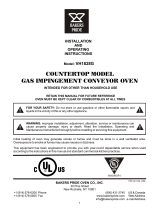
ERROR CODES
Error codes will display as fl ashing text messages for diagnostic purposes. Any temperature or thermocouple
error should turn the temperature output OFF and leave the conveyor running at the same speed. The
belt error should turn the temperature output OFF. The speed error should display when the motor is
unable to settle at the chosen speed. This might occur if a fast speed is chosen that the motor is unable
to spin fast enough to achieve. The speed signal output will remain the same but the display will fl ash
the error message.
CONTROLLER SENSES
NO SIGNAL FROM T/C
OR REVERSED WIRING
SPEED IS OUT
OF RANGE
BUT MOTOR IS
FUNCTIONING
TO SET CALIBRATION & RESET MEMORY:
POWER OFF, HOLD BUTTONS 1,2&3
POWER ON (DONE WHEN SEt CAL SHOWS)
WARNING: TEMP CALIBRATION WILL BE OFF
UNLESS T/C SIMULATOR (SET FOR 300 °C)
IS ATTACHED BEFORE TURNING POWER ON
ALERT MESSAGE:
DISPLAYS WHEN MEMORY
PROBLEMS ARE DETECTED
FLASHING GREEN LED IS OFF
THIS WILL SHOW WHEN BUTTON #3 IS
PUSHED DURING INITIAL PREHEATING
A NUMBER WILL NOT BE DISPLAYED IF
ADJUSTED TEMP IS LOWER THAN 140 °F
OR 60°C (DEPENDENT ON UNITS DISPLAYING)
THIS WILL SHOW FOR TWO (2) SECONDS EVERY
FIFTEEN (15) SECONDS WHEN TACH SIGNAL IS
LOST AND TACH FEEDBACK IS ENABLED.
IL1188
OPERATION
/