Page is loading ...

INSTRUCTION MANUAL
MODEL 2455T SUBCARRIER MODULATOR
CROSS TECHNOLOGIES, INC.
6170 SHILOH ROAD
ALPHARETTA, GEORGIA 30005
(770) 886-8005
FAX (770) 886-7964
web www.crosstechnologies.com
e-mail [email protected]
Data, drawings, and other material contained herein are
proprietary to Cross Technologies, Inc., and may not be
reproduced or duplicated in any form without the prior
permission of Cross Technologies, Inc.
When ordering parts from Cross Technologies, Inc., be
sure to include the equipment model number, equipment
serial number, and a description of the part.
First Edition, JUNE 2002 6/17/02 Rev 0

INSTRUCTION MANUAL
MODEL 2455T SUBCARRIER MODULATOR
TABLE OF CONTENTS PAGE
Warranty ..............................................2
1.0 General.................................................3
1.1 Equipment Description..........................3
1.2 Technical Characteristics........................3
2.0 Installation ............................................4
2.1 Mechanical .......................................4
2.2 Controls and Indicators..........................4
2.3 Input / Output Signals ..........................4
2.4 Removing PCB from Extrusion................4
2.5 Installation / Operation .........................5
2.5.1 Operation .................................5
3.0 Circuit Description...................................7
3.1 Block Diagram Description ....................7
WARRANTY - The following warranty applies to all Cross Technologies, Inc. products.
All Cross Technologies, Inc. products are warranted against defective materials and workmanship for a period
of one year after shipment to customer. Cross Technologies, Inc.’s obligation under this warranty is limited to
repairing or, at Cross Technologies, Inc.’ option, replacing parts, subassemblies, or entire assemblies. Cross
Technologies, Inc. shall not be liable for any special, indirect, or consequential damages. This warranty does
not cover parts or equipment which have been subject to misuse, negligence, or accident by the customer
during use. All shipping costs for warranty repairs will be prepaid by the customer. There are not other
warranties, express or implied, except as stated herein.
CROSS TECHNOLOGIES, INC.
6170 SHILOH ROAD
ALPHARETTA, GEORGIA 30005
(770) 886-8005
FAX (770) 886-7964
web www.crosstechnologies.com
e-mail [email protected]
2455T manual Rev. 0 Page 2 6/17/02

MODEL 2455T SUBCARRIER MODULATOR
SECTION 1 GENERAL
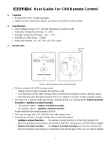
1.1 Equipment Description- The Model 2455T Subcarrier modulator provides an FM modulated signal in the 5.4 to 8.5
MHz subcarrier band at a frequency set at the factory and specified by the customer. The 2455T provides non-emphasized, 150
kHz peak deviation for a 1.0 Vrms input into a balanced 600 ohm input impedance. The output provides 50 to 250 mV p-p out
into 75 ohms. Audio connectors are barrier strip and the subcarrier output connector is BNC female. The unit is mounted on a
standard 19”, 1 3/4 “ high rack mount panel and DC power is supplied by a wall mount power supply.
Model 2455T Modulator
2455T MODULATOR
AUDIOCARRIER
LEVEL ALARM
PEAK LEVEL
CROSS TECHNOLOGIES, INC.
FIGURE 1.0 Model 2455T Subcarrier Modulator
1.2 Technical Characteristics
TABLE 1.0 2455T MODULATOR SPECIFICATIONS
Characteristics Specifications*
Audio Input Characteristics
Impedance 600 ohms, balanced
Frequency 50 Hz to 120 kHz
Input Level Factory set for 1 Vrms into 600Ω for 150 kHz Peak deviation (adjustable)
SC Output Characteristics
Impedance > 1.5K ohms (bridging)
Frequency range 5.4 - 8.5 MHz, factory set
Level 50 - 250 mVp-p into 75 Ω
Channel Characteristics
Deviation 150 kHz peak
Pre-emphasis None
Frequency Response ≤ ±1.0 dB, 50 Hz - 120 kHz
Distortion ≤ 1 %, 1 kHz
Controls
Output level adjust 10 turn pot adjusts the subcarrier output over 50 - 250 mV p-p
Input level adjust 10 turn pot adjusts the audio deviation; factory set for 1 Vrms for 150 kHz peak deviation
Indicators
PLL/ALC Alarm Red LED (with open collector out)
Peak Deviation Yellow Led, lights at PPL audio level
Other
DC Power, max. +15VDC, 125 ma; -15VDC, 50ma; via wall power supply
RF, IF Connectors BNC, female
*+10 to +40 degrees C; Specifications subject to change without notice
2455T manual Rev. 0 Page 3 6/17/02

2.0 Installation
2.1 Mechanical - The 2455T Modulator PCB is packaged in an aluminum extrusion. The 2455T is mounted on a 1 3/4” X
19” panel that can be mounted to a rack using the 4 holes at the ends. The unit derives ± 15V from the wall power supply. See
Figure 2.1.
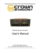
2.2 Controls and Indicators - Figure 2.2 shows front panel controls and indicators.
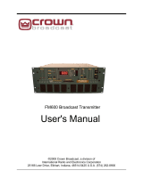
2.3 Input / Output Signals - Figure 2.3 shows the input and output signals to the 2455T.
2.4 Removing the Printed Circuit Board (PCB) From the Extrusion - There are no on-card jumpers or other on-
card controls. To remove the printed circuit board (PCB) from the extrusion:
1.) Remove four (4) rear
panel screws (see Figure 2.1).
2.) Gently pull the backplane and PCB assembly completely out of the extrusion.
3.) Always remove power when removing or installing the PCB in to the extrusion. Make sure the shield goes in the
lower channel and the PCB in the next channel above that in the extrusion.
4.) Gently push the backplane and PCB assembly completely in to the extrusion.
5.) Install four (4) rear panel screws.
2455T manual Rev. 0 Page 4 6/17/02
FRONT SCREWS (4EA,
UNDER FRONT PANEL)
RACK MOUNT PANEL
FIGURE 2.1 SERIES 2700 ASSEMBLY DRAWING
EXTRUSION
BACKPLANE
REAR SCREWS (4EA)
FRONT PANEL
PCB ASSEMBLY
WALL
POWER
SUPPLY
CROSS TECHNOLOGIES, INC.
FRONT PANEL
FASTENERS (2EA)

2.5 Installation / Operation -
2.5.1 Operation -
1.) Connect the wall power supply to the 2455T and the wall power supply to 115 VAC, 60 Hz (Figure 2.1)
2) AUDIO INPUT - Pins 16 and 17 of J4 (terminal strip on the back panel, see Figure 2.3 and Table 2.1) are the
balanced audio inputs. Pin 18 is ground.
3) SUBCARRIER OUTPUT - The subcarrier output is available on J1, the BNC connector on the back panel
(Figure 2.3). JP1 may be placed in the “TERM” position for a 75 ohm termination. If video is being looped
through, this jumper it should be placed in “non-term” (JP1 pins 2 -3) position. Use a BNC “T” to add the subcarrier
output to the video if using the high impedance loop through. Be sure a 75 Ω termination is provided at some point in
the loop, preferably at the end.
4.) The output level is adjustable from 50 to 250 mV p-p into a 75 ohm load with R65 (Figure 2.2).
5.) The alarm indicator CR1 (Figure 2.2) will illuminate if the output level is adjusted beyond the ALC range of the
module. It will also illuminate if the PLL comes out of lock.
6.) The peak deviation indicator, CR8 (Figure 2.2) flashes when the modulator exceeds 150 kHz /peak deviation.
FIGURE 2.2 2455T Front Panel Controls and Indicators
R65- SC Output
Level Adjustment
- Ten turn
potentiometer that
adjusts the subcarrier
output level. It can be
adjusted for 50 to 250
mV p-p into 75 Ω.
CR1 - Alarm LED -
Lights red when PLL
comes out of lock or
the output is not ALC’d
CR8 - Peak Deviation LED -
Lights yellow when the audio
exceeds levels for peak deviation
R10- Audio Level
Adjustment - Ten
turn potentiometer
that adjusts the audio
level. Factory set for
150 kHz Peak
deviation for 1 Vrms
input.
2455T MODULATOR
CROSS TECHNOLOGIES, INC.
AUDIOCARRIER
LEVEL ALARM
PEAK LEVEL
2455T manual Rev. 0 Page 5 6/17/02

J2
FIGURE 2.3 2455T Inputs and Outputs
J4 - I/O BARRIER STRIP - Provides connections for
audio, data, alarm signals, etc. Pin numbers are as shown
upside down on the connector. See Table 2.1
J2 - DC IN - The
+15 VDC AND -15
VDC regulated DC
voltage from the
wall power supply
-15 +15
GND
J1 - BNC IN/OUT - Signal from pin 2 or 3 (as
set by strap beside J1) of PCB which is for
subcarrier, video, IF and RF signals.
JP1 - J1 OUTPUT
TERMINATION
TERM = 75Ω TERMINATION
2 - 3 = NO 75Ω TERMINATION
1 2 3
JP1
TERM
J4
TABLE 2.1 INPUT AND OUTPUT SIGNALS
TABLE 2.1 INPUT AND OUTPUT SIGNALS
CONNECTOR GENERAL FUNCTION 2455T FUNCTION COMMENTS
J1 BNC IN/OUT SUBCARRIER OUTPUT 50 TO 250 MV P-P
J2 DC IN DC IN ± 15 VDC, 3PIN MINI-DIN
J3 PCB EDGE CONNECTOR PCB EDGE CONNECTOR INTERNAL USE
J4 - PIN
1 GROUND GROUND
2 BB IN/OUT NOT USED
3 RF/IF OUT/IN. NOT USED
4 +AUDIO - L; +CLK NOT USED
5 -AUDIO - L; -CLK; RS232 NOT USED
6 MISC; AGC; CC; BCD-0 NOT USED
7 UNBAL AUDIO - L. NOT USED
8 MISC; CC; BCD-1 NOT USED
9 +15 VOLTS. +15 VOLTS.
10 MISC; CC; BCD-2 NOT USED
11 -15 VOLTS -15 VOLTS
12 MISC; CC; BCD-3 NOT USED
13 UNBAL AUDIO - R. NOT USED
14 MISC; CC; NOT USED
15 ALARM; CC. ALARM OPEN COLLECTOR (+30 VDC, 30ma MAX).
16 +AUDIO - R ; +DATA. +AUDIO IN 1 Vrms at PPL, 600Ω balanced for 150 kHz Peak
17 -AUDIO - R ; -DATA; RS232. -AUDIO 1 Vrms at PPL, 600Ω balanced for 150 kHz Peak
18 GROUND GROUND
2455T manual Rev. 0 Page 6 6/17/02

3.0 Circuit Description
3.1 Block Diagram Description - 2455T (Figure 3.1) -
The subcarrier modulator generates a frequency modulated carrier in the 5.4 to 8.5 MHz range for use in a subcarrier
transmission system. Its output power is variable, permitting various injection levels. Refer to Figure 3.1 and the following
detailed description.
The FM oscillator is a varactor tuned, modified Colpitts oscillator whose frequency is stabilized by a phase locked-loop (PLL) to
a crystal reference. The output from the FM oscillator is amplified in the ALC amplifier to a sufficient level for use in the
transmission system. The bandpass filter is a three pole LC filter with a bandwidth sufficient to pass the FM carrier and its
significant sidebands. An emitter follower isolates the output from external conditions. The output impedance is relatively high
(nominally 2 k ohms), permitting bridging onto a low impedance baseband with minimal loading. A portion of the output is
sampled for control of the alarm and mute circuit. Should the unloaded carrier level decrease below 40 mV p-p either by failure,
loading, or external mute, the ALC and muting circuit biases the ALC amplifier off and activates the alarm circuitry. The alarm
circuit consists of several logic gates which monitor the PLL performance and status of the ALC bias. Should the PLL break
lock, U4 detects the PLL state and:
a. Biases Q3 on for external alarm indications.
b. Illuminates CR1 to provide a visual indication of alarm
c. Biases U5B positive which, in turn, shuts off the ALC amplifier.
The external mute (available in some models) forces a similar condition and causes alarm conditions
The PLL system maintains frequency stability of the FM oscillator. A portion of the FM oscillator output is sampled in U3; the
crystal standard oscillator is sampled in U1. The resulting square waves OUT of U1 and U3 respectively are processed in the
PLL, U2. The PLL attempts to maintain phase lock between U3 and U1 outputs by providing a DC bias which is filtered in the
PLL filter, and applied to the varactor diode in the FM oscillator. The summing junction, U6B, sums the modulating frequency
with the DC bias, then applies the composite baseband to the varactor diode, CR7. The center frequency of the FM oscillator is
dependent on the DC component of composite baseband provided by Vref, which stabilizes the capacitance of CR7. The PLL
filter has a very slow time constant which prevents excessive frequency shift of the FM oscillator due to modulation.
2455T manual Rev. 0 Page 7 6/17/02

2455T manual Rev. 0 Page 8 6/17/02
/