Page is loading ...

Manual
EN
Handleiding
NL
Manuel
FR
Anleitung
DE
Manual
ES
Användarhandbok
SE
Manuale
IT
Appendix
SmartSolar charge controller MPPT 150/35

1
EN NL FR DE ES SE IT Appendix
1. General Description
1.1 Charge current up to 35A and PV voltage up to 150V
The SmartSolar MPPT 150/35 charge controller is able to charge
a lower nominal-voltage battery from a higher nominal voltage PV
array.
The controller will automatically adjust to a 12V, 24V or a 48V
nominal battery voltage.
1.2 Ultra-fast Maximum Power Point Tracking (MPPT)
Especially in case of a clouded sky, when light intensity is
changing continuously, an ultra fast MPPT controller will improve
energy harvest by up to 30% compared to PWM charge
controllers and by up to 10% compared to slower MPPT
controllers.
1.3 Advanced Maximum Power Point Detection in case of
partial shading conditions
If partial shading occurs, two or more maximum power points may
be present on the power-voltage curve.
Conventional MPPTs tend to lock to a local MPP, which may not
be the optimum MPP.
The innovative SmartSolar algorithm will always maximize energy
harvest by locking to the optimum MPP.
1.4 Outstanding conversion efficiency
No cooling fan. Maximum efficiency exceeds 98%. Full output
current up to 40°C (104°F).
1.5 Extensive electronic protection
Over-temperature protection and power derating when
temperature is high.
PV short circuit and PV reverse polarity protection.
PV reverse current protection.
1.6 Internal temperature sensor
Compensates absorption and float charge voltages for
temperature.
(range 6°C to 40°C)
1.7 Optional external voltage and temperature sensor
(
range -20°C to 50°C)
The Smart Battery Sense is a wireless battery voltage-and-
temperature sensor for Victron MPPT Solar Chargers. The Solar
Charger uses these measurements to optimize its charge

2
parameters. The accuracy of the data it transmits will improve
battery charging efficiency, and prolong battery life.
Alternatively, Bluetooth communication can be set up between a
BMV-712 battery monitor with battery temperature sensor and the
solar charge controller.
For more detail please enter smart networking in the search box
on our website.
1.8 Automatic battery voltage recognition
The MPPT 150/35 will automatically adjust itself to a 12V, 24V or
a 48V system one time only. If a different system voltage is
required at a later stage, it must be changed manually, for
example with the Bluetooth app, see section 1.11.
1.9 Flexible charge algorithm
Fully programmable charge algorithm, and eight preprogrammed
algorithms, selectable with a rotary switch.
1.10 Adaptive three step charging
The BlueSolar MPPT Charge Controller is configured for a three
step charging process: Bulk – Absorption – Float.
1.10.1. Bulk
During this stage the controller delivers as much charge current
as possible to rapidly recharge the batteries.
1.10.2. Absorption
When the battery voltage reaches the absorption voltage setting,
the controller switches to constant voltage mode.
When only shallow discharges occur the absorption time is kept
short in order to prevent overcharging of the battery. After a deep
discharge the absorption time is automatically increased to make
sure that the battery is completely recharged. Additionally, the
absorption period is also ended when the charge current
decreases to less than 2A.
1.10.3. Float
During this stage, float voltage is applied to the battery to
maintain it in a fully charged state.
1.10.4. Equalization
See section 3.8

3
EN NL FR DE ES SE IT Appendix
1.11 Remote on-off
The MPPT 150/35 can be controlled remotely by a VE.Direct non
inverting remote on-off cable (ASS030550320). An input HIGH
(Vi > 8V) will switch the controller on, and an input LOW (V < 2V,
or free floating) will switch the controller off.
Application example: on/off control by a VE.Bus BMS when
charging Li-ion batteries.
1.12 Configuring and monitoring
Configure the solar charge controller with the VictronConnect
app. Available for iOS & Android devices; as well as macOS and
Windows computers. An accessory might be required; enter
victronconnect in the search box on our website and see the
VictronConnect download page for details.
For simple monitoring, use the MPPT Control; a panel mounted
simple yet effective display that shows all operational parameters.
Full system monitoring including logging to our online portal,
VRM, is done using the GX Product range
MPPT Control
Color Control
Venus GX

4
2. IMPORTANT SAFETY INSTRUCTIONS
SAVE THESE INSTRUCTIONS - This manual contains
important instructions that shall be followed during
installation and maintenance.
● Please read this manual carefully before the product is
installed and put into use.
● This product is designed and tested in accordance with
international standards. The equipment should be used for
the designated application only.
● Install the product in a heatproof environment. Ensure
therefore that there are no chemicals, plastic parts, curtains or
other textiles, etc. in the immediate vicinity of the equipment.
● The product is not allowed to be mounted in a user accessible
area.
● Ensure that the equipment is used under the correct operating
conditions. Never operate it in a wet environment.
● Never use the product at sites where gas or dust explosions
could occur.
● Ensure that there is always sufficient free space around the
product for ventilation.
● Refer to the specifications provided by the manufacturer of the
battery to ensure that the battery is suitable for use with this
product. The battery manufacturer's safety instructions should
always be observed.
● Protect the solar modules from direct light during
installation, e.g. cover them.
● Never touch uninsulated cable ends.
● Use only insulated tools.
● Connections must always be made in the sequence described
in section 3.6.
● The installer of the product must provide a means for cable
strain relief to prevent the transmission of stress to the
connections.
● In addition to this manual, the system operation or service
manual must include a battery maintance manual applicable to
the type of batteries used.
Danger of explosion from sparking
Danger of electric shock

5
EN NL FR DE ES SE IT Appendix
3. Installation
WARNING: DC (PV) INPUT NOT ISOLATED FROM BATTERY
CIRCUIT
CAUTION: FOR PROPER TEMPERATURE COMPENSATION
THE AMBIENT CONDITION FOR CHARGER AND BATTERY
MUST BE WITHIN 5°C.
3.1. General
● Mount vertically on a non-flammable substrate, with the power
terminals facing downwards. Observe a minimum clearance of 10 cm
under and above the product for optimal cooling.
● Mount close to the battery, but never directly above the battery (in
order to prevent damage due to gassing of the battery).
● Improper internal temperature compensation (e.g. ambient condition
battery and charger not within 5°C) can lead to reduced battery
lifetime.
We recommend using a direct battery voltage sense source (BMV,
Smart Battery Sense or GX device shared voltage sense) if larger
temperature differences or extreme ambient temperature
conditions are expected.
● Battery installation must be done in accordance with the storage
battery rules of the Canadian Electrical Code, Part I.
● The battery and PV connections must be guarded against
inadvertent contact (e.g. install in an enclosure or install the optional
WireBox M).
3.2 Grounding
● Battery grounding: the charger can be installed in a positive or
negative grounded system.
Note: apply a single ground connection (preferably close to the battery)
to prevent malfunctioning of the system.
● Chassis grounding: A separate earth path for the chassis ground is
permitted because it is isolated from the positive and negative
terminal.
● The USA National Electrical Code (NEC) requires the use of an
external ground fault protection device (GFPD). These MPPT chargers
do not have internal ground fault protection. The system electrical
negative should be bonded through a GFPD to earth ground at one
(and only one) location.
● The charger must not be connected with grounded PV arrays. (one
ground connection only)
● The plus and minus of the PV array should not be grounded. Ground
the frame of the PV panels to reduce the impact of lightning.

6
WARNING: WHEN A GROUND FAULT IS INDICATED,
BATTERY TERMINALS AND CONNECTED CIRCUITS MAY BE
UNGROUNDED AND HAZARDOUS.
3.3. PV configuration (also see the MPPT Excel sheet on our
website)
● Provide a means to disconnect all current-carrying conductors
of a photovoltaic power source from all other conductors in a
building or other structure.
● A switch, circuit breaker, or other device, either ac or dc, shall
not be installed in a grounded conductor if operation of that
switch, circuit breaker, or other device leaves the grounded
conductor in an ungrounded state while the system remains
energized.
● The controller will operate only if the PV voltage exceeds
battery voltage (Vbat).
● PV voltage must exceed Vbat + 5V for the controller to start.
Thereafter minimum PV voltage is Vbat + 1V.
● Maximum open circuit PV voltage: 150V.
For example:
24V battery and mono- or polycristalline panels
● Minimum number of cells in series: 72 (2x 12V panel in series
or one 24V panel).
● Recommended number of cells for highest controller efficiency:
144 cells (4x 12V panel or 2x 24V panel in series).
● Maximum: 216 cells (6x 12V or 3x 24V panel in series).
48V battery and mono- or polycristalline panels
● Minimum number of cells in series: 144 (4x 12V panel or
2x 24V panel in series).
● Maximum: 216 cells.
Remark: at low temperature the open circuit voltage of a 216 cell
solar array may exceed 150V, depending on local conditions and
cell specifications. In that case the number of cells in series must
be reduced.
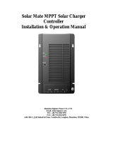
3.4 Cable connection sequence (see figure 1)
First: connect the battery.
Second: connect the solar array (when connected with reverse
polarity, the controller will heat up but will not charge the battery).
Torque: 1,6 Nm

7
EN NL FR DE ES SE IT Appendix
3.5 Configuration of the controller
Fully programmable charge algorithm (see the software page on
our website) and eight preprogrammed charge algorithms,
selectable with a rotary switch:
Pos
Suggested battery
Type
Absorption
V
Float
V
Equalize
V
@%I
nom
dV/dT
mV/°C
0
Gel Victron long life (OPzV)
Gel exide A600 (OPzV)
Gel MK
28,2 27,6
31,8
@8%
-32
1
Gel Victron deep discharge
Gel Exide A200
AGM Victron deep discharge
Stationary tubular plate
(OPzS)
28,6 27,6
32,2
@8%
-32
2
Default setting
Gel Victron deep discharge
Gel Exide A200
AGM Victron deep discharge
Stationary tubular plate
(OPzS)
28,8 27,6
32,4
@8%
-32
3
AGM spiral cell
Stationary tubular plate
(OPzS)
Rolls AGM
29,4 27,6
33,0
@8%
-32
4
PzS tubular plate traction
batteries or
OPzS batteries
29,8 27,6
33,4
@25%
-32
5
PzS tubular plate traction
batteries or
OPzS batteries
30,2 27,6
33,8
@25%
-32
6
PzS tubular plate traction
batteries or
OPzS batteries
30,6 27,6
34,2
@25%
-32
7
Lithium Iron Phosphate
(LiFePo
4
) batteries
28,4 27,0 n.a. 0
Note 1: divide all values by two in case of a 12V system and multiply by two
in case of a 48V system.
Note 2: equalize normally off, see sect. 3.8 to activate.
(do not equalize VRLA Gel and AGM batteries)
Note 3: any setting change performed with Bluetooth or via VE.Direct will
override the rotary switch setting. Turning the rotary switch will override prior
settings made with Bluetooth or VE.Direct.

8
On all models with software version V 1.12 or higher a binary
LED code helps determining the position of the rotary switch.
After changing the position of the rotary switch, the LEDs will
blink during 4 seconds as follows:
Thereafter, normal indication resumes, as described below.
Remark: the blink function is enabled only when PV power is
present on the input of the controller.
3.6 LEDs
LED indication:
permanent on
blinking
off
Regular operation
LEDs
Bulk
Absorption
Float
Bulk (*1)
Absorption (*2)
Automatic equalisation (*2)
Float (*2)
Note (*1): The bulk LED will blink briefly every 3 seconds when the system is powered but
there is insufficient power to start charging.
Note (*2): The LED(s) might blink every 4 seconds indicating that the charger is receiving
data from another device, this can be:
• A GX Device (eg Color Control with a Multi in ESS mode)
• A VE.Smart network link via Bluetooth (with other MPPT chargers and / or a
BMV or Smart Battery Sense)
Fault situations
LEDs
Bulk
Absorption
Float
Charger temperature too high
Charger over-current
Charger over-voltage
Internal error (*3)
Note (*3): E.g. calibration and/or settings data lost, current sensor issue.
Switch
position
LED
Bulk
LED
Abs
LED
Float
Blink
frequency
0
1
1
1
Fast
1
0
0
1
Slow
2
0
1
0
Slow
3
0
1
1
Slow
4
1
0
0
Slow
5
1
0
1
Slow
6
1
1
0
Slow
7
1
1
1
Slow

9
EN NL FR DE ES SE IT Appendix
For the latest and most up to date
information about the blink codes,
please refer to the Victron Toolkit app.
Click on or scan the QR code to get
to the Victron Support and
Downloads/Software page.
3.7 Battery charging information
The charge controller starts a new charge cycle every morning,
when the sun starts shining.
Lead-acid batteries: default method to determine length and
end of absorption
The charging algorithm behaviour of MPPTs differs from AC
connected battery chargers. Please read this section of the
manual carefully to understand MPPT behaviour, and always
follow the recommendations of your battery manufacturer.
By default, the absorption time is determined on idle battery
voltage at the start of each day based on the following table:
Battery voltage Vb
(@start-up)
Multiplier
Maximum
absorption time
Vb < 11,9V x 1 6h
11,9V < Vb < 12,2V x 2/3 4h
12,2V < Vb < 12,6V x 1/3 2h
Vb > 12,6V x 1/6 1h
(12V values, adjust for 24V))
Default absorption voltage: 14,4V
Default float voltage: 13,8V
The absorption time counter starts once switched from bulk to
absorption.

10
The MPPT Solar Chargers will also end absorption and switch to
float when the battery current drops below a low current threshold
limit, the ‘tail current’.
The default tail current value value is 2A.
The default settings (voltages, absorption time multiplier and tail
current) can be modified with the Victronconnect app via
Bluetooth or via VE.Direct.
There are two exceptions to normal operation:
1. When used in an ESS system; the solar charger algorithm is
disabled; and instead it follows the curve as mandated by the
inverter/charger.
2. For CAN-bus Lithium batteries, like BYD, the battery tells the
system, including the solar charger, what charge voltage to
use. This Charge Voltage Limit (CVL) is for some batteries
even dynamic; changes over time; based on for example
maximum cell voltage in the pack and other parameters.
When, in case of the above-mentioned exceptions, several Solar
Chargers are connected to a GX device, these chargers will
automatically be synchronised.
Variations to expected behaviour
1. Pausing of the absorption time counter
The absorption time counter starts when the configured
absorption voltage is reached and pauses when the output
voltage is below the configured absorption voltage.
An example of when this voltage drop could occur is when PV
power (due to clouds, trees, bridges) is insufficient to charge
the battery and to power the loads.
When the absorption timer is paused, the absorption LED will
flash very slowly.
2. Restarting the charge process
The charging algorithm will reset if charging has stopped (i.e.
the absorption time has paused) for an hour. This may occur
when the PV voltage drops below the battery voltage due to
bad weather, shade or similar.
3. Battery being charged or discharged before solar charging
begins
The automatic absorption time is based on the start-up battery

11
EN NL FR DE ES SE IT Appendix
voltage (see table). This absorption time estimation can be
incorrect if there is an additional charge source (eg alternator)
or load on the batteries.
This is an inherent issue in the default algorithm. However, in
most cases it is still better than a fixed absorption time
regardless of other charge sources or battery state.
It is possible to override the default absorption time algorithm
by setting a fixed absorption time when programming the solar
charge controller. Be aware this can result in overcharging your
batteries. Please see your battery manufacturer for
recommended settings.
4. Absorption time determined by tail current
In some applications it may be preferable to terminate
absorption time based on tail current only. This can be
achieved by increasing the default absorption time multiplier.
(warning: the tail current of lead-acid batteries does not
decrease to zero when the batteries are fully charged, and this
“remaining” tail current can increase substantially when the
batteries age)
Default setting, LiFePO4 batteries
LiFePO4 batteries do not need to be fully charged to prevent
premature failure.
The default absorption voltage setting is 14,2V (28,4V).
And the default absorption time setting is 2 hours.
Default float setting: 13,2V (26,4V).
These settings are adjustable.
Reset of the charge algorithm:
The default setting for restarting the charge cycle is
Vbatt < (Vfloat – 0,4V) for lead-acid, and Vbatt < (Vfloat – 0,1V)
for LiFePO4 batteries, during 1 minute.
(values for 12V batteries, multiply by two for 24V)
3.8 Automatic equalization
Automatic equalization is default set to ‘OFF’. With the Victron
Connect app (see sect 1.12) this setting can be configured with a
number between 1 (every day) and 250 (once every 250 days).
When automatic equalization is active, the absorption charge will
be followed by a voltage limited constant current period. The
current is limited to 8% or 25% of the bulk current (see table in

12
sect. 3.5). The bulk current is the rated charger current unless a
lower maximum current setting has been chosen.
When using a setting with 8% current limit, automatic equalization
ends when the voltage limit has been reached, or after 1 hour,
whichever comes first.
Other settings: automatic equalization ends after 4 hours.
When automatic equalization is not completely finished within one
day, it will not resume the next day, the next equalization session
will take place as determined by the day interval.

13
EN NL FR DE ES SE IT Appendix
4. Troubleshooting
Problem
Possible cause
Solution
Charger does not
function
Reversed PV connection Connect PV correctly
Reverse battery
connection
Non replacable fuse
blown.
Return to VE for repair
The battery is not fully
charged
A bad battery connection
Check battery
connection
Cable losses too high
Use cables with larger
cross section
Large ambient
temperature difference
between charger and
battery (T
ambient_chrg
>
T
ambient_batt
)
Make sure that
ambient conditions
are equal for charger
and battery
Only for a 24V or 48V
system: wrong system
voltage chosen by the
charge controller
Set the controller
manually to the
required system
voltage (see section
1.11)
The battery is being
overcharged
A battery cell is defect
Replace battery
Large ambient
temperature difference
between charger and
battery (T
ambient_chrg
<
T
ambient_batt
)
Make sure that
ambient conditions
are equal for charger
and battery

14
5. Specifications
SmartSolar charge controller MPPT 150/35
Battery voltage
12/24/48V Auto Select (36V: manual)
Maximum battery current
35A
Nominal PV power, 12V 1a,b)
500W (MPPT range 15V to 130V)
Nominal PV power, 24V 1a,b)
1000W (MPPT range 30V to 130V)
Nominal PV power, 48V 1a,b)
2000W (MPPT range 60V to 130V)
Max. PV short circuit current 2)
40A
Maximum PV open circuit voltage
150V
Peak efficiency
98%
Self consumption
10mA
Charge voltage 'absorption'
Default setting: 14,4V / 28,8V / 57,6V (adjustable)
Charge voltage 'equalization' 3)
Default setting: 16,2V / 32,4V / 64,8V (adjustable)
Charge voltage 'float'
Default setting: 13,8V / 27,6V / 55,2V (adjustable)
Charge algorithm
Multi-stage adaptive (eight preprogrammed algorithms)
or user defined algorithm
Temperature compensation
-16mV / -32mV / -68mV / °C
Protection
Battery reverse polarity (fuse, not user accessible)
Output short circuit / Over temperature
Operating temperature
-30 to +60°C (full rated output up to 40°C)
Humidity
95%, non-condensing
Maximum altitude
5000m (full rated output up to 2000m)
Environmental condition
Indoor type 1, unconditioned
Pollution degree
PD3
Data communication port and
remote on/off
VE.Direct (see the data communication white paper on
our website)
ENCLOSURE
Colour
Blue (RAL 5012)
Power terminals
16mm² / AWG6
Protection category
IP43 (electronic components), IP 22 (connection area)
Weight
1,25kg
Dimensions (h x w x d)
130 x 186 x 70 mm
STANDARDS
Safety
EN/IEC 62109-1, UL 1741, CSA C22.2
1a) If more PV power is connected, the controller will limit input power.
1b) The PV voltage must exceed Vbat + 5V for the controller to start.
Thereafter the minimum PV voltage is Vbat + 1V.
2) A higher short circuit current may damage the controller in case of reverse
polarity connection of the PV array.
3) Default setting: OFF

EN NL FR DE ES SE IT Appendix
Figure 1: Power connections

/