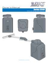
DKS 6002 User manual

Category
Gate Opener
Type
User manual

This manual is also suitable for

Actuator Arm and
Control Box Mounting
6002
6002
6002
Copyright 2013 DoorKing, Inc. All rights reserved.
Vehicular Swing Gate Operator
UL 325 Compliant
To wire this operator and complete the installation, refer to a specific control box “Wiring/Owner’s manual”.
6002-065-Z-2-15
6002-065-Z-2-15
1
Class of Operation Model 6002 - UL 325 Class I
Type of Gate Vehicular Swing Gates Only
Actuator Arm Voltage 24 VDC
Current 3 Amps
Motor RPM 1400
Maximum Thrust 300 daN
Max Gate Weight 500 Lbs.
Max Gate Length 14 Feet
Useful Rod Stroke 14 inches of travel
Cycles Per Hour 10 Per Hour with AC connected (Cycles will vary with battery power ONLY)
Speed 90° in approximately 15 seconds
Control Box Types 115 VAC 60 Hz Single Phase Input Power - 24 VDC Output Power to Gate Operators
24 Volt Solar Input Power - 24 VDC Output Power to Gate Operators
6002 SPECIFICATIONS
DoorKing, Inc. reserves the right to make changes in the products described in this manual without notice and without obligation of DoorKing, Inc. to notify any persons
of any such revisions or changes. Additionally, DoorKing, Inc. makes no representations or warranties with respect to this manual. This manual is copyrighted, all rights
reserved. No portion of this manual may be copied, reproduced, translated, or reduced to any electronic medium without prior written consent from DoorKing, Inc.
49.25”
5.75”
3”
3.5”
Actuator Arm
3.75”
6002-065-Z-2-15
2
SPECIFICATIONS 1
6002 Specifications
ASTM F2200 Standard for Gate Construction
Important Safety Instructions
Instructions regarding intended installation:
Important Notices
UL 325 Entrapment Protection
Glossary
Swing Gate Requirements
Swing Gate Protection
1
3
3
3
4
5
6
7
8
INSTALLATION 9
9
10
11
12
13-14
15
15
16
17
18
Manual Key Release
Gate “Opens to the Inside” Installation
Gate “Opens to the Outside” Installation
Mounting Actuator Arm
Mounting Control Box with Conduit
Install Warning Signs
In-Ground Loops
Photo Sensor Positions “Opens to the Inside”
Accessory Items
6002 Primary/Secondary 4302 Circuit Board Connection
TABLE OF CONTENTS
6002-065-Z-2-15
3
Instructions regarding intended installation:
Vehicular gates should be constructed and installed in accordance with ASTM F2200; Standard Specification for Automated
Vehicular Gate Construction. For a copy of this standard, contact ASTM directly at 610-832-9585; [email protected]; or
www.astm.org.
Important Safety Instructions
WARNING - To reduce the risk of injury or death:
1. READ AND FOLLOW ALL INSTRUCTIONS.
2. Never let children operate or play with gate controls. Keep the remote control away from children.
3. Always keep people and objects away from gate. NO ONE SHOULD CROSS THE PATH OF THE MOVING GATE.
4. Test the operator monthly. The gate MUST reverse on contact with a rigid object or stop or reverse when an object
activates the non-contact sensors. After adjusting the force or the limit of travel, retest the gate operator. Failure to adjust
and retest the gate operator properly can increase the risk of injury or death.
5. Use the emergency release only when the gate is not moving.
6. KEEP GATES PROPERLY MAINTAINED. Read the owner's manual. Have a qualified service person make repairs to gate
hardware.
7. The entrance is for vehicles only. Pedestrians must use separate entrance.
8. SAVE THESE INSTRUCTIONS!
Install the gate operator only if:
1. The operator is appropriate for the construction of the gate and the usage class of the gate.
2. All openings of a horizontal slide gate are guarded or screened from the bottom of the gate to a minimum of 6 feet
(1.83 m) above the ground to prevent a 2 ¼ inch (57.2 mm) diameter sphere from passing through the openings
anywhere in the gate, and in that portion of the adjacent fence that the gate covers in the open position.
3. All exposed pinch points are eliminated or guarded.
4. Guarding is supplied for exposed rollers.
The operator is intended for installation only on gates used for vehicles. Pedestrians must be supplied with a separate
access opening. The pedestrian access opening shall be designed to promote pedestrian usage. Locate the gate such that
persons will not come in contact with the vehicular gate during the entire path of travel of the vehicular gate.
The gate must be installed in a location so that enough clearance is supplied between the gate and adjacent structures
when opening and closing to reduce the risk of entrapment. Swinging gates should not open into public access areas.
The gate must be properly installed and work freely in both directions prior to the installation of the gate operator. Do not
over-tighten the operator clutch, pressure relief valve or reduce reversing sensitivity to compensate for a damaged gate.
For gate operators utilizing Type D protection:
1. The gate operator controls must be placed so that the user has full view of the gate area when the gate is moving.
2. A warning placard shall be placed adjacent to the controls.
3. An automatic closing device (such as a timer, loop sensor, or similar device) shall not be employed.
4. No other activation device shall be connected.
Controls intended for user activation must be located at least ten feet (10’) away from any moving part of the gate and
where the user is prevented from reaching over, under, around or through the gate to operate the controls. Outdoor or
easily accessible controls should have a security feature to prevent unauthorized use.
The Stop and/or Reset button must be located in the line-of-sight of the gate. Activation of the reset control shall not
cause the operator to start.
A minimum of two (2) WARNING SIGNS shall be installed, one on each side of the gate where easily visible.
For gate operators utilizing a non-contact sensor:
1. See the instructions on the placement of non-contact sensors for each type of application.
2. Care shall be exercised to reduce the risk of nuisance tripping, such as when a vehicle trips the sensor while the gate
is still moving in the opening direction.
3. One or more non-contact sensors shall be located where the risk of entrapment or obstruction exist, such as the
perimeter reachable by a moving gate or barrier.
ASTM F2200 Standard for Gate Construction
6002-065-Z-2-15
4
For gate operators utilizing contact sensors:
1. One or more contact sensors shall be located where the risk of entrapment or obstruction exist, such as at the
leading edge, trailing edge, and post mounted both inside and outside of a vehicular horizontal slide gate.
2. One or more contact sensors shall be located at the bottom edge of a vehicular vertical lift gate.
3. One or more contact sensors shall be located at the pinch point of a vehicular vertical pivot gate.
4. A hardwired contact sensor shall be located and its wiring arranged so that the communication between the sensor
and the gate operator is not subjected to mechanical damage.
5. A wireless contact sensor such as one that transmits radio frequency (RF) signals to the gate operator for
entrapment protection functions shall be located where the transmission of the signals are not obstructed or
impeded by building structures, natural landscaping or similar obstructions. A wireless contact sensor shall function
under the intended end-use conditions.
6. One or more contact sensors shall be located at the bottom edge of a vertical barrier (arm).
Vehicular gate operator products provide convenience and security. However, gate operators must use high levels of force
to move gates and most people underestimate the power of these systems and do not realize the potential hazards associ-
ated with an incorrectly designed or installed system. These hazards may include:
Pinch points
Entrapment areas
Reach through hazards
Absence of entrapment protection devices
Improperly located access controls
Absence of vehicle protection devices
Absence of controlled pedestrian access
In addition to these potential hazards, automated vehicular gate systems must be installed in accordance with the UL 325
Safety Standard and the ASTM F2200 Construction Standard. Most lay persons are unaware of, or are not familiar with,
these standards. If an automated vehicular gate system is not properly designed, installed, used and maintained, serious
injuries or death can result. Be sure that the installer has instructed you on the proper operation of the gate and gate
operator system.
Be sure that the installer has trained you about the basic functions of the required reversing systems associated with your
gate operating system and how to test them. These include reversing loops, inherent reversing system, electric edges,
photoelectric cells, or other external devices.
This Owner’s Manual is your property. Keep it in a safe place for future reference.
Be sure that all access control devices are installed a minimum distance of 10 feet away from the gate and gate
operator, or in such a way that a person cannot touch the gate or gate operator while using the device. If access
control devices are installed in violation of these restrictions, immediately remove the gate operator from service
and contact your installing dealer.
Loops and loop detectors, photo-cells or other equivalent devices must be installed to prevent the gate from
closing on vehicular traffic.
The speed limit for vehicular traffic through the gate area is 5 MPH. Install speed bumps and signs to keep
vehicular traffic from speeding through the gate area. Failure to adhere to posted speed limits can result in
damage to the gate, gate operator, and to the vehicle.
Be sure that all persons who will use the gate system are familiar with the proper use of the gate and gate
operator and are familiar with the possible hazards associated with the gate system.
Be sure that warning signs are permanently installed on both sides of the gate in an area where they are fully
visible to traffic.
It is your responsibility to periodically check all entrapment protection devices. If any of these devices are
observed to function improperly, remove the operator from service immediately and contact your installing or
servicing dealer.
Follow the recommended maintenance schedule.
Do not allow children to play in the area of the operator or to play with any gate-operating device.
To remove the gate operator from service, operate the gate to the full open position and then shut off power to
the operator at the service panel.
Important Notices
6002-065-Z-2-15
5
UL 325 Entrapment Protection
Class I
Class I and II
Class III
Class IV
Class II
Class III Class IV
A vehicular gate operator (or system) intended for use in a
home of one-to four single family dwelling, or a garage or
parking area associated therewith.
A vehicular gate operator (or system) intended for use in a
commercial location or building such as a multi-family
housing unit (five or more single family units) hotel,
garages, retail store or other building servicing the general
public.
A vehicular gate operator (or system) intended for use in a
industrial location or building such as a factory or loading
dock area or other locations not intended to service the
general public.
A vehicular gate operator (or system) intended for use in a
guarded industrial location or building such as an airport
security area or other restricted access locations not
servicing the general public, in which unauthorized access
is prevented via supervision by security personnel.
This table illustrates the entrapment protection requirements for each of the four UL 325 classes.
A - Inherent entrapment protection system.
B1 - Provision for connection of, or supplied with, a non-contact sensor (photoelectric sensor or the equivalent).
When used as the PRIMARY device, must be monitored.
B2 - Provision for connection of, or supplied with, a contact sensor (edge device or the equivalent).
When used as the PRIMARY device, must be monitored.
C - Inherent adjustable clutch or pressure relief device.
D - Provision for connection of, or supplied with, an actuating device requiring continuous pressure to maintain
opening or closing motion of the gate.
E - An inherent audio alarm.
STATE PRISON
UL 325
Classifications
Horizontal Slide, Vertical Lift, Vertical Pivot Swing and Vertical Barrier (arm)
Primary Protection
A B1, B2 or D A, B1, B2, C or D A or C
A, B1 or B2 A, B1, B2, D or E A, B1, B2, C or D A, B1, B2 or C
A, B1, B2 or D A, B1, B2, D or E A, B1, B2, C, D or E A, B1, B2, C or D
Secondary Protection Primary Protection Secondary Protection
6002-065-Z-2-15
6
Glossary
GATE - A moving barrier such as a swinging, sliding, raising, lowering, or the like, barrier, that is a stand-alone passage
barrier or is that portion of a wall or fence system that controls entrance and/or egress by persons or vehicles and
completes the perimeter of a defined area.
RESIDENTIAL VEHICULAR GATE OPERATOR – CLASS I - A vehicular gate operator (or system) intended for use in a home
of one-to four single family dwelling, or garage or parking area associated therewith.
COMMERCIAL / GENERAL ACCESS VEHICULAR GATE OPERATOR - CLASS II - A vehicular gate operator (or system)
intended for use in a commercial location or building such as a multi-family housing unit (five or more single family units),
hotels, garages, retail store, or other building servicing the general public.
INDUSTRIAL / LIMITED ACCESS VEHICULAR GATE OPERATOR - CLASS III - A vehicular gate operator (or system)
intended for use in an industrial location or building such as a factory or loading dock area or other locations not intended
to service the general public.
RESTRICTED ACCESS VEHICULAR GATE OPERATOR - CLASS IV - A vehicular gate operator (or system) intended for use in
a guarded industrial location or building such as an airport security area or other restricted access locations not servicing
the general public, in which unauthorized access is prevented via supervision by security personnel.
VEHICULAR BARRIER (ARM) OPERATOR (OR SYSTEM) - An operator (or system) that controls a cantilever type device (or
system), consisting of a mechanical arm or barrier that moves in a vertical arc, intended for vehicular traffic flow at
entrances or exits to areas such as parking garages, lots or toll areas.
VEHICULAR HORIZONTAL SLIDE-GATE OPERATOR (OR SYSTEM) - A vehicular gate operator (or system) that controls a
gate which slides in a horizontal direction that is intended for use for vehicular entrance and exit to a drive, parking lot, or
the like.
VEHICULAR SWING-GATE OPERATOR (OR SYSTEM) - A vehicular gate operator (or system) that controls a gate which
moves in an arc in a horizontal plane that is intended for use for vehicular entrance and exit to a drive, parking lot, or the
like.
SYSTEM - In the context of these requirements, a system refers to a group of interacting devices intended to perform a
common function.
WIRED CONTROL - A control implemented in a form of fixed physical interconnections between the control, the associated
devices, and an operator to perform predetermined functions in response to input signals.
WIRELESS CONTROL - A control implemented in means other than fixed physical interconnections (such as radio waves or
infrared beams) between the control, the associated devices, and an operator to perform predetermined functions in
response to input signals.
INHERENT ENTRAPMENT PROTECTION SYSTEM - A system, examples being a motor current or speed sensing system,
which provides protection against entrapment upon sensing an object and is incorporated as a permanent and integral part
of the operator.
EXTERNAL ENTRAPMENT PROTECTION DEVICE - A device, examples being an edge sensor, a photoelectric sensor, or
similar entrapment protection device, which provides protection against entrapment when activated and is not incorporated
as a permanent part of an operator.
ENTRAPMENT - The condition when an object is caught or held in a position that increases the risk of injury.
6002-065-Z-2-15
7
Swing Gate Requirements
The operator is intended for installation only on gates used for vehicles. Pedestrians must be supplied with a separate
access opening. The pedestrian access opening shall be designed to promote pedestrian usage. Locate the gate such that
persons will not come in contact with the vehicular gate during the entire path of travel of the vehicular gate.
(ref. UL325 56.8.4.b)
Not Allowed OK
Closed Gates
Gates shall have smooth bottom edges, with vertical bottom edged protrusions not exceeding 0.50 inches. ASTM F2200 4.3
If distance is greater than 4 inches,
entrapment protection for this area is
required. ASTM F2200 7.1.1.1
If distance is less than 16 inches,
entrapment protection in this area
is required. ASTM F2200 7.1.1.2
A
B
A
B
Closed Gate
With the hinge mounted on
the corner of the pilaster,
the entrapment area is
eliminated and protection
is NOT required for this
area.
Closed Gate
Opened Gate
Opened Gate
A
6002-065-Z-2-15
8
Swing Gate Protection
Non-contact Sensor
C
D
D
C
Separate Pedestrian
Walkway
Located so pedestrians
cannot come in contact
with the vehicular gate.
Minimizes the potential
of the gate closing on
vehicular or other traffic
that loops cannot sense.
See page 16 for typical
layout locations.
Warning Signs
D
Permanently mounted
and easily visible from
either side of the gate.
Moving Gate Can Cause
Serious Injury or Death
KEEP CLEAR! Gate may move at any time
without prior warning.
Do not let children operate the gate or play
in the gate area.
This entrance is for vehicles only.
Pedestrians must use separate entrance.
Reverse Loop
Shadow Loop
Automatic Exit Loop
Minimizes the potential of the gate
closing when a vehicle is present.
Number and placement of loops is
dependent on the application.
Reverse Loop
Minimizes the potential of the gate
closing when a vehicle is present.
Number and placement of loops is
dependent on the application.
(Optional) will provide an open
command to the gate operator(s)
when a vehicle is exiting the
property.
Secure Side of Gate
See page 15 for typical loop layout locations.
Non-Secure Side of Gate
Provides a hold open command to
the operator(s) only if the gate(s)
are at the full open position.
Note: Not used for solar control
box installations.
6002-065-Z-2-15
9
OPEN
18
OPEN
OPEN
OPEN
OPEN
OPEN
Removing
Actuator
Cover
INSTALLATION
Manual Release
Prior to beginning
the installation of the
swing gate operator, we
suggest that you become famil-
iar with the instructions and illustra-
tions in this manual. This will help insure
that your installation is performed in an
efficient and professional manner compliant with UL
325 safety and ASTM F2200 construction standards.
The proper installation of the vehicular slide gate operator is an
extremely important and integral part of the overall access control
system.
Check all local building ordinances and building codes prior
to installing this operator. Be sure your installation is in compliance with
local codes.
Use key to unlock and remove the cover.
Actuator cover removed.
Remove allen wrench from inside of cover.
Insert allen wrench
and turn 180° to release the arm.
Remove 3 screws
and slide cover off.
DO NOT
remove
this screw.
Sample Installation
115 VAC Standard Control Box
Dual Gate Operators “Opening to the Inside”
Hinge Placement Note: It’s important to consider hinge placement on a pilaster or a thick wall
when installing the gate. Placing hinges close to the corner can eliminate a potential entrapment
area (See Swing Gate Requirements on page 7).
6002-065-Z-2-15
10
A support bar must span
the entire length of the
gate to support the gate
pickets. The pickets will
bend if not supported.
Support Bar
“Opening to the Inside” Installation
46
3
/4” Closed Position
7”
7”
90°
Gate Hinge Pivot Point
Reinforcing steel plate
for sleeve anchors
if desired.
(Not Supplied)
Reinforcing steel plate
for bolts if desired.
(Not Supplied)
Weld directly
to gate OR
to steel plate
Weld directly
to support post
OR to steel plate
Front Bracket Pivot Point
Rear Bracket
Support Post
Front Bracket
Rear Bracket Pivot Point
Open Position
(Cover On)
Closed Position
(Cover Off)
Do not install the actuator in fully
extended (Bottomed out) position.
This will damage the arm. See page
12 to prevent this from happening.
Weld front and rear brackets directly to gate and metal support
post if desired.
If mounting brackets with bolts to the gate and wall, weld reinforcing
steel plates to the brackets.
Note: The brackets must be perpendicular (Plumb) to the gate and
wall/post and horizontally level. Weld completely around brackets.
3
1
/8
Mounting Brackets to Surfaces
Gate in Closed Position
Actuator arm MUST be level!
Bottom Installation Note:
Make sure that the operator is
mounted high enough off the
ground that it will NOT come
in contact with standing or
flowing water. This will
damage the operator.
Bottom
Middle
Top
Front
Bracket
(Supplied)
Rear Bracket
(Supplied)
2 7/8”
1/4”
With reinforced steel plate -
6002-065-Z-2-15
11
“Opening to the Outside” Installation
Open Position
(Cover Off)
Closed Position
(Cover On)
A support bar must span
the entire length of the
gate to support the gate
pickets. The pickets will
bend if not supported.
Support Bar
Gate in Closed Position
Actuator arm MUST be level!
7”
Addition to rear
bracket must be
fabricated to
reach wall.
Gate Hinge Pivot Point
Front Bracket
Pivot Point
Front Bracket
Rear Bracket Pivot Point
90°
7”
Do not install the
actuator in fully
extended (Bottomed
out) position. This will
damage the arm. See
next page to prevent
this from happening.
Bottom Installation
Note: Make sure
that the operator is
mounted high
enough off the
ground that it will
NOT come in
contact with
standing or flowing
water. This will
damage the
operator.
46
3
/4” Open Position
Fabricated
Reinforced
Steel Plate
(Not Supplied)
Rear
Bracket
(Supplied)
Bottom
Middle
Top
Reinforcing steel plate
for bolts if desired.
(Not Supplied)
Weld directly
to gate OR
to steel plate
Front
Bracke
t
(Supplied)
Weld front bracket and fabricated rear bracket directly to gate and metal support post if desired.
If mounting brackets with bolts to the gate and wall, weld reinforcing steel plates to the brackets.
Note: The brackets must be perpendicular (Plumb) to the gate and
wall/post and horizontally level. Weld completely around brackets.
Mounting Brackets to Surfaces
Weld directly
to support post
OR to steel plate
Support Post
Reinforcing steel plate
for sleeve anchors
if desired.
(Not Supplied)
2 7/8”
1/4”
3
1
/8
- With reinforced steel plate
6002-065-Z-2-15
12
Mounting Actuator Arm
Gate must be in good working condition before the actuator arm can be installed. Determine what direction the actuator arm
will open the gate “Opening to the Inside” or “Opening to the Outside” (See previous two pages).
The brackets need to be fabricated before the arm can be installed. Brackets will vary in size depending on the opening direction
of the gate and the thickness of the wall the actuator arm will attach to. They can be attached to the wall and gate by welding
and/or mechanically, depending on the type wall and gate. The brackets must be perpendicular to the wall and/or gate and
horizontally level. Make sure the brackets will be VERY secure when fastened to the wall and gate.
It is very important that the powered shaft is not fully extended when installed on the gate (bottoming out). This will damage the
arm. To prevent this, manually release the arm and fully extend the powered shaft. Rotate it back two full turns before installing
the arm.
A support bar that spans the entire length of the gate must be installed to keep the pickets from bending. Do not mount the
front bracket directly to gate pickets!
Bracket Fabrication
Clevis Pins
Gate Support Bar
Prevent Powered Shaft from Bottoming Out
Powered shaft rotated back 2 turns.
Fully Extended (Bottomed Out)
OPEN
OPEN
OPEN
OPEN
Manually release
with allen wrench.
Powered Shaft
Actuator arm MUST be level!
Retaining Ring
Retaining Ring
Rear Pin
(Short)
Front Pin
(Long)
Note: Front clevis pin MUST fit
into countersunk hole to allow
retaining ring to be installed.
If brackets are going to be welded to the gate and/or wall, only tack weld the brackets with the arm attached. Protect the arm
from welding sparks during tack welding. Remove arm before completely welding around the brackets. Make sure the
brackets are level when tack welding them! The arm will not operate properly if not level.
Welding Brackets to Surfaces
6002-065-Z-2-15
13
Mounting Control Box with Conduit
Primary
Actuator
Cable
Secondary Actuator Conduit
Control Box must be
properly grounded.
Input Power Conduit
115 VAC
Loops Conduit
3/4” conduit recommended. Use only sweeps for conduit bends and NOT elbow connectors. Elbows will make
wire pulls very difficult and can cause damage to wire insulation.
Remove fragile components from control box to protect them during installation if necessary.
Coaxial Cable Antenna Kit
P/N 1514-073 (Sold separately)
Primary
Actuator
Cable
Secondary
Actuator
Cable
DoorKing interconnection cable (Sold separately) inside underground conduit
Junction
Box
Junction
Boxes
Elbow
NO
Sweep
YES
Interconnection Cable 30 feet. P/N 2600-755
Interconnection Cable 40 feet. P/N 2600-756
Interconnection Cable 50 feet. P/N 2600-757
PRIMARY Actuator
PRIMARY Actuator
SECONDARY Actuator
From Secondary Operator if Installed (See below)
High
Voltage
Low
Voltage
Low
Voltage
Permanent wiring must be installed to the operator as required by local electrical codes (See the 115 VAC control box
Wiring/Owner’s manual or Solar control box Wiring/Owner’s manual to wire operator). It is recommended that a licensed
electrical contractor perform this work. Check local building codes prior to installing any permanent wiring to ensure all wiring
and connections comply with local electrical code requirements.
Position the desired control box on the wall, close enough to the operator so the primary actuator cable can be easily routed
inside the box. Make sure that the control box is mounted high enough off the ground that it will NOT come in contact with
standing or flowing water. This will damage the internal components. Secure the control box to the wall with appropriate
hardware (not included). Control box has pre drilled mounting holes. All power and control wires should be routed to control
box in conduits with sweeps. Never run low voltage rated wire insulation in the same conduit as high voltage rated wire
insulation.
115 VAC Control Box
Dual Actuators Connection (115 VAC or Solar)
6002-065-Z-2-15
14
PRIMARY Actuator
Mounting Control Box Continued
Primary
Operator
Cable
Secondary Operator Conduit
Input Power
Conduit
Loops Conduit
24 Volt 10 Watt
Solar Panel
P/N 2000-077
24 Volt 20 Watt
Solar Panel
P/N 2000-076
Mounting Pole
Not Provided
Flexible Conduit
Junction
Boxes
Elbow
NO
Sweep
YES
Conduit
From Secondary Operator if Installed (See previous page)
Solar Control Box
Solar Cabinet
Mounting Holes
and Conduit
Holes
3/4” Conduit
Knockouts
Mounting
H
oles
Mounting Hole
3/4” Conduit
Knockouts
Antenna
Hole
Cabinet
Back
DoorKing offers a mounting
post kit (P/N 1000-045)
when no vertical surface is
available to mount the solar
control box cabinet to.
Cover
Mounti
ng Post
Mount to
C
oncrete
To attach post to concrete,
DoorKing recommends four
(4) 3/8” x 3” sleeve anchors
(not supplied). Do Not mount
post on asphalt.
Cabinet
Back
Loops
Typical conduit
configuration
(not supplied).
Remove fragile
components
from control
box to protect
them during
installation if
necessary.
Low
Voltage
Primary Operator
Secondary Operator
Solar
Power
F
lexible
C
onduit
Low
Voltage
Low
Voltage
Low
Voltage
ONLY Mount One 24 Volt Solar Panel!
The 24 volt - 10 watt or 20 watt solar panel must be correctly
installed for the system to function correctly. See the solar control
box Wiring/Owner’s manual for more information about concerns,
considerations and recommendations for proper solar panel
positioning and mounting.
DO NOT use a 12 volt solar panel. Damage WILL occur!!
3/4” conduit
recommended.
Coaxial
Cable
Antenna
Kit
P/N
1514-073
(Sold
separately)
One 24 V 10 watt panel
required for 18 Amp/Hr
batteries. DO NOT USE
10 watt panel with the
35 Amp/Hr batteries.
One 24 V 20 watt panel required
for 35 Amp/Hr batteries.
DO NOT USE 20 watt panel with
the18 Amp/Hr batteries.
6002-065-Z-2-15
15
Reverse
Shadow
Automatic Exit
Automatic
Exit Loop
Automatically opens the gate
for exiting vehicles without
having to use a transmitter or
keypad. The exit loop can be
placed a minimum of 4 feet
away from the reverse loop or
far enough away from the gate
so the gate has started or
completely opened by the time
you drive up to it (Free exit).
To help protect the operator from accidentally
closing on vehicles in the gate’s path,
DoorKing highly recommends that
loops and loop detectors be
installed. Loops are laid underneath,
cut into asphalt or concrete drive-
ways or buried beneath gravel and
earth driveways. A loop detection
system will sense a vehicle like a
metal detector and send a signal to
the gate operator preventing the gate
from automatically opening or
closing on a vehicle when it is in the
gate’s path. DoorKing recommends
that a licensed installer perform this
work.
4 Ft. min. to avoid gate
moveme
nt int
erference.
4 Ft. min. to avoid
reverse loop interference.
DoorKing offers a free “Loop and Loop-Detectors
Information Manual” PDF located at Doorking’s
web site for more information. www.dkaccess.com
4 Ft. min.
To avoid gate
movement interference.
Loop lead-in wires are twisted
approx. 6 twists per foot in PVC
conduit to the control box.
Reverse
Shadow Loop The shadow loop is placed
inside the gate’s swinging path to prevent the
gate from closing on a vehicle in this area. It is
only active when the gate is in the full open
position. Vehicles in the shadow area will
activate it. It will not allow the gate to close
unless this area is clear. After a closing cycle
begins, the shadow loop will not reverse the
gate. Reverse loops work in conjunction with
the shadow loop and both should be used.
Reverse Loops
Reverse loops are placed just outside the
gate’s swinging path to prevent the gate from
closing on a vehicle in these areas. They will
reverse the cycling of the gate while a vehicle
is in or near the gate’s swing pathway.
Control Box
Cover the exposed holes on top of
the actuator with the aluminum tape.
Do not cover the holes on
the bottom of actuator.
Cover Holes on Top Install Warning Signs
This DoorKing Swing Gate Operator is shipped with two
warning signs. The purpose of the warning sign is to alert
uninformed persons, and to remind persons familiar with the
gate system, that a possible hazard exists so that appropriate
action can be taken to avoid the hazard or to reduce exposure
to the hazard. See page 8 for suggested mounting positions
of signs.
Permanently install the
supplied warning signs in
locations so that the signs
are visible by persons on
both sides of the gate.
Use appropriate hardware
such as wood or sheet metal
screws (not supplied) to install
the warning signs.
In-Ground Loops
Loop Lead-In Wires
(Low Voltage)
Shadow Loop Note:
Not used for solar
control box installations.
6002-065-Z-2-15
16
Potential
Hazard Area
Photo Sensor Positions “Opening to the Inside”
Non-Secure Side
Outside Property
Secure Side
Inside Property
Closing-Direction
Side End View
or less
5”
Gate Frame Closed
Closing-Direction Photo Beam
21”
Typical
Opening-Direction
Side View
Wall
If this space is less than 16 inches,
secondary entrapment protection
is required in this area.
Gate Frame Closed
UL sensor mounted just
below actuator arm cable.
Gate Frame Open
Gate Frame Closed
Opening-Direction
Photo Beam
Potential
Entrapment
Area
Gate Frame Closed
Top View
Top View
Secondary Entrapment Protection Device:
In addition to the inherent reversing sensor system, the Model 6002 has a 6-pin UL 325 terminal for the connection of photo sensors-Type B1
secondary entrapment protection device required by UL 325 standards (see 115 VAC or Solar control box wiring manual). Entrapment
protection devices must be installed to reduce the risk of injury. Install these devices where the risk of entrapment or a hazard exists while the
gate is moving. Specific installations will vary.
Potential
Pinch Point
Hazard Area
Potential
Pinch Point
Hazard Area
Low Voltage
6002-065-Z-2-15
17
Accessory Items
The following accessory items are available for the model 6002 swing gate operator.
Control Box Types - Fully controls actuator arm(s) with built-in battery back-up system.
P/N 4302-111 - 115 VAC Standard Control Box, 115 VAC 60 Hz Input to box, 24 VDC output to gate operator.
P/N 4302-112 - 115 VAC Deluxe Control Box, 115 VAC 60 Hz Input to box, 24 VDC output to gate operator. 3-115 VAC convenience outlets.
P/N 4302-114 - 18 ah Solar Control Box, 24 VDC 20 Watt Input to box, 24 VDC output to gate operator. 2 - 12 Volt 18 Amp Hr batteries.
P/N 2000-075 - One (1) 24 volt 10 watt solar panel required for 18 ah solar control box.
P/N 4302-115 - 35 ah Solar Control Box, 24 VDC 20 Watt Input to box, 24 VDC output to gate operator. 2 - 12 Volt 35 Amp Hr batteries.
P/N 2000-075 - Two (2) 24 volt 10 watt solar panels required for 35 ah solar control box.
Photo Sensor - Non-contact sensors (photo-cells) sensors for use as a secondary entrapment protection device.
EMX Industries, Inc. Model IRB-325
MMTC, Inc. Model E3K-R10K4-NR
Loop Hardware - DoorKing offers a complete line of loop components to complete your gate operator system.
See DoorKing’s web site - www.doorking.com
See the free manual “Loop and Loop-Detectors Information” PDF located at Doorking’s technical web site - www.dkaccess.com
Magnetic Lock - Magnetic Gate Lock Kit provides an excellent means to secure swing gates and is a fail-safe device allowing emergency
vehicle access upon power outage.
P/N 1216-080 and P/N 1216-081
Interconnection Cable - Interconnect wire cable contains all the necessary wires to interconnect primary / secondary operators.
Cable length 30 feet. P/N 2600-755 Cable length 40 feet. P/N 2600-756 Cable length 50 feet. P/N 2600-757
Time Clock - 7 day and 365 day time clocks can be used to automatically open gate at pre-set time and days. Compact clock fits inside the
control box.
P/N 2600-791 - 7 day clock
P/N 2600-795 - 365 day clock
Hinges - Heavy-duty ball bearing hinges provide easy swing gate operation.
P/N 1200-009 (Flange) , P/N 1200-019, P/N 1200-039. Two (2) required.
Speed Bumps - Prefabricated six-foot speed bump reduces traffic speed through gate system. P/N 1610-150
6002-065-Z-2-15
18
6002 Primary/Secondary 4302 Circuit Board Connection
Secondary Actuator
Secondary
Connection
ONLY
Primary
Connection
ONLY
1
7
6
5
4
3
2
12345
6
7
89
10 11 12
13
14 15
16 17 18 19
20
1
7
6
5
4
3
2
12345 67
12345 67
Brown
Purple
Gray
Motor
Yellow
Blue and Brown
Primary Actuator
Close-up of Wiring in Actuator
Brown 1
Blue 2
Orange 3
Red 4
Yellow 5
Green 6
Green/Yellow 7
Brown 1
Blue 2
Orange 3
Red 4
Yellow 5
Green 6
Green/Yellow 7
A
1 Brown
2 Blue
3 Orange
4 Red
5 Yellow
6 Green
7 Green/Yellow
12345 67
12345 67
A
(Motor) Brown 1
(Motor) Blue 2
(Limit) Gray 3
(Slow Down) Purple 4
(Limit) Yellow 5
(Slow Down) Brown 6
(Common) 4 White Wires 7
Limit Assembly Limit Assembly
12345 67
12345 67
Brown
Purple
Gray
White Wires
White Wires
Motor
Yellow
Blue and Brown
A
Limit Assembly Limit Assembly
4302
  • Page 1 1
  • Page 2 2
  • Page 3 3
  • Page 4 4
  • Page 5 5
  • Page 6 6
  • Page 7 7
  • Page 8 8
  • Page 9 9
  • Page 10 10
  • Page 11 11
  • Page 12 12
  • Page 13 13
  • Page 14 14
  • Page 15 15
  • Page 16 16
  • Page 17 17
  • Page 18 18
  • Page 19 19
  • Page 20 20
  • Page 21 21
  • Page 22 22

DKS 6002 User manual

Category
Gate Opener
Type
User manual
This manual is also suitable for

Ask a question and I''ll find the answer in the document

Finding information in a document is now easier with AI