HySecurity Nice Signo Owner's manual

Type
Owner's manual

HySecurity Nice Signo is an electromechanical barrier operator designed for automating access points with barrier arms up to 12 or 20 feet in length. It features precise motor control with deceleration at stroke limits and obstacle detection for enhanced safety. SIGNO can operate in manual, semi-automatic, and automatic modes, with configurable functions such as automatic closing, traffic light signaling, and a cycle counter for maintenance scheduling. Optional accessories are available to expand its functionality.

HySecurity Nice Signo is an electromechanical barrier operator designed for automating access points with barrier arms up to 12 or 20 feet in length. It features precise motor control with deceleration at stroke limits and obstacle detection for enhanced safety. SIGNO can operate in manual, semi-automatic, and automatic modes, with configurable functions such as automatic closing, traffic light signaling, and a cycle counter for maintenance scheduling. Optional accessories are available to expand its functionality.

1I
ISTSG REV 00.01
INSTALLATION MANUAL
Manufactured by NICE SpA
Rev 810
2
1
2
A B
SIGNO4
SIGNO6
12.6”
11.4”
13.4”
12.2”
8.7” 16.5”
42.1”
42.1”
Arm and connector
sold seperatly
3
4 5
7
3
6
4
8 9
1110
12
5
1 Warnings..............................................................................................................................................................6
2 Product description..............................................................................................................................................6
2.1 Operating limits...........................................................................................................................................7
3 Installation ...........................................................................................................................................................7
3.1 Checks and preliminary operations.............................................................................................................7
3.2 Typical system (fig. 3) ................................................................................................................................8
3.3 Fixing ..........................................................................................................................................................8
3.4 Connection to the power supply..................................................................................................................8
3.5 Electrical diagram .......................................................................................................................................9
3.6 Description of connections........................................................................................................................10
3.7 Notes on electrical connections.................................................................................................................10
3.8 Description of the Stop input.....................................................................................................................10
3.9 Phototest....................................................................................................................................................11
3.10 Checking the connections.....................................................................................................................11
4 Programming and adjustments...........................................................................................................................12
4.1 Mechanical stops initial search..................................................................................................................12
4.2 Mechanical stops automatic search...........................................................................................................12
4.3 Manual programming of deceleration positions........................................................................................13
4.4 Save procedure..........................................................................................................................................13
4.5 Memory delete...........................................................................................................................................14
4.6 Adjustments...............................................................................................................................................14
4.6.1 Torque adjustment............................................................................................................................14
4.6.2 Speed adjustment..............................................................................................................................14
4.6.3 Pause time adjustment......................................................................................................................14
5 Testing and commissioning ...............................................................................................................................15
6 Selectable functions...........................................................................................................................................16
6.1 Functions description ................................................................................................................................16
7 What to do if…..................................................................................................................................................17
8 Manual or release operation...............................................................................................................................18
9 Maintenance.......................................................................................................................................................18
9.1 Planning of maintenance work..................................................................................................................18
9.2 Alarm ....................................................................................................................................................... 19
10 Disposal .............................................................................................................................................................20
11 Technical specifications.....................................................................................................................................20
11.1 Control unit specifications ........................................................................................................................20
Addendum – New universal control unit. Model SIA20/A.................................................................................. 21-22
6
1 Warnings
Read these instructions before proceeding with the installation work. They contain important information regarding safety,
installation, use and maintenance.
In order to make the use of these instructions as simple as possible, we have tried to follow the same order as the various
phases of installation. All operations not specified in these instructions are not allowed; improper use may damage the product
and endanger persons and property.
Store this manual safely for future use.
This manual, as well as the design and manufacture of the devices that make up SIGNO, comply fully with the standards and
regulations in force.
Considering the hazards that may exist during the installation and operation of SIGNO, it is necessary that also the installation
be carried out in strict compliance with current legislation, standards and regulations, particularly:
Before you start with the installation, check whether additional devices or materials are needed to complete the
automation with SIGNO based on the specific application requirements.
The automation system must not be used until it has been commissioned as described in the heading: Testing and
commissioning.
The packing materials must be disposed of in compliance with local regulations.
Do not make modifications to any components unless such action is specified in this manual. Operations of this type
are likely to lead to malfunctions. NICE and APOLLO disclaim any liability for damage resulting from modified
products.
Do not immerse the automation parts in water or any other liquid. During installation, ensure that liquids do not leak
into the control unit or other open devices.
In the event that liquid substances have penetrated inside the automation devices, immediately disconnect the power
supply and contact the APOLLO customer service department. The use of SIGNO in these conditions can be
dangerous.
Keep all components of SIGNO away from heat sources and open flames; these could damage the components and
cause malfunctions, fire or dangerous situations.
During long periods of inactivity, the optional battery should be removed and stored in a dry location to prevent
leakage of noxious substances.
Connect the control unit only to a power supply line equipped with safety grounding system.
All operations requiring the opening of the door of the SIGNO device must be performed with the control unit
disconnected from the power supply; if the disconnection device is not identifiable, affix a notice to the effect:
“WARNING: MAINTENANCE WORK IN PROGRESS”.
In the event that any automatic switches are tripped or fuses blown, you must identify the fault and eliminate it before
resetting the switches or replacing fuses.
If a fault occurs that cannot be solved using the information provided in this manual, refer to the APOLLO customer service
department.
2 Product description
SIGNO is an electromechanical barrier operator including foundation plate, bracket for attachment of a rectangular section
arm, and control unit.
The automation system is designed to reach its stroke limit positions (opening and closing strokes) with a
deceleration phase, while monitoring motor load during the movement.
Thanks to these control systems any obstacles encountered in the range of the stroke are identified immediately
causing reversal of the direction of movement (current sensor function). The system can be used in "manual",
"semiautomatic” and "automatic" mode with functions such as “Close 0 sec. after Photo”, “Always close" and two
types of traffic light signalling. The control unit includes a cycle counter that allows management through time of
system maintenance interventions, and it is also prearranged for inclusion of radio receivers with SM slot.
Optional accessories are available for all versions.
SIGNO 4 . Serves to automate an access protected by means of a barrier arm of up to 12 ft in length
SIGNO 6 . Serves to automate an access protected by means of a barrier arm of up to 20 ft in length
7
2.1 Operating limits
3 Installation
Note that automatic gate and door systems must be installed exclusively by qualified technical personnel in full
compliance with statutory regulations. Before starting the installation work read the instructions in the following
manual carefully.
3.1 Checks and preliminary operations
Check that the package is intact. After removing the cover and the door, check that the pack contains all the parts
shown in Fig. 1
No. 4 Anchors - M12
No. 4 Washers 12 mm
No. 4 Locknuts - M12
No. 2 Screws - 4.2 x 9.5
No. 1 Bar support bracket
No. 1 Pair of keys for release procedure
No. 1 Pair of keys for cover
No. 4 Screws - M8 x 16
No. 1 Foundation plate
No. 1 Bar cover
No. 1 Printed cap
No. 1 Front cap
Referring to Fig. 2, check that the installation site is compatible with the dimensions of the barrier. Warning:
check whether the arm is to be installed on the right (R) or left (L)
Check for the absence of obstructions that could impede movement of the arm during the opening and closing
movements.
Check that the supporting base for SIGNO is solid and suitably sized.
Check that the barrier installation site is compatible with easy and safe operation.
Make sure that the mounting positions of the various devices are protected from impacts and that the mounting
surfaces are sufficiently sturdy.
SIGNO4 up to 12 ft
Arm with complete set of
accessories
SIGNO6 up to 20 ft
Arm with complete set of
accessories and limits for speed
8
3.2 Typical system (fig. 3)
1 . Signo
2 . Aluminium arm
3 . Key-operated selector switch
4 . Post for selector switch
5 . Post for photocells
6 . Photocell
7 . Red rubber protective strip
8 . Safety edge or red rubber strip
9 . Flashing signal lights
10. Red reflector strips
11. Aerial
12. Flashing light
3.3 Installation
1. Embed the supplied foundation plate in a suitably sized concrete pad. The plate must be flush with the surface of
the pad, perfectly level, and with the exposed surface perfectly clean, taking care not to damage the thread of the
anchor bolts and providing the facility for at least one or more conduit for the routing of electrical cables.
Warning: the plate must be parallel to the arm.
Fig. 4
2. Place SIGNO on the previously installed base and secure it with the supplied nuts and washers.
Fig. 5
3. If necessary, invert the position of the spring, moving it from the right to the left. Warning: the arm will be
positioned vertically when the spring is in its relaxed position.
Fig. 6
4. Fit the arm with the specific bracket supplied and secure it by tightening the 4 screws.
Fig. 7
5. Perform the release procedure (see chapter 8 "Manual or release procedure”)
6. Bring the arm to its horizontal position and install any optional accessories required.
7. Balance the arm by means of the spring adjuster tension rod. The arm can be considered to be properly balanced
when, positioned at an angle of 45°, it neither tends to descend nor move upwards.
Fig. 8
WARNING: once
the balancing procedure is terminated tighten the tension rod nuts.
8. Horizontal and vertical linear alignment can be adjusted by means of the travel limit cushioning devices
Fig. 9
9. Relock the barrier by performing step 5 in reverse.
10. If the SIGNO accessories are not used or only certain accessories are used, the balancing procedure can be
facilitated by fixing the spring in one of the available holes
Fig. 10
3.4 Connection to the power supply
Connect the 110V supply cable directly to the terminal.
Fig. 11
Secure with the specific cable clamp.
9
3.5 Electrical diagram
The following figure shows the layout of the electronic board with an indication of the main components and
the wiring connections.
110 VAC
10
3.6 Description of connections
1-2 Phase - Neutral = Mains power supply
3-4 Flashing light = 24 Vdc max 25W flashing light output
5-6 Electric lock/Suction
cup = 24Vdc max 250 mA electric lock/suction cup output
7-8 Phototest = Phototest output
9-10 24 Vdc = 24 Vdc max. 200mA services power supply
11 Common = Common for all inputs
12 Sca = Barrier open output (LED on = barrier open; LED off = barrier closed; high
frequency flashing = closing phase; low frequency flashing = opening phase)
13 Cor = Courtesy light output (activated at the start of a cycle and remains active for
60 seconds after the cycle is concluded)
14 Man = Maintenance LED output
15 Sync = Barriers synchronism
16 Stop = STOP input (Emergency, trip, or extreme safety), normally closed type (NC)
or constant 8.2K resistance type (heading 3.8)
17 Foto = NC type input for safety devices (Photocells, pneumatic safety edges)
operational during the closing phase
18 Step-by-Step = Input for cyclic Open – Stop – Close – Stop operation
19 Open = Input for opening movement with cyclic Open – Stop – Open – Stop
operation
20 Close = Input for closing movement with cyclic Close – Stop – Close – Stop
operation
Aerial = Input for radio receiver aerial
Battery = Connection of plug-in card for battery charger
3.7 Notes on electrical connections
To ensure the safety of the operator and prevent damage to components, while making connections or plugging
in the radio receiver the control unit must be disconnected from the mains power supply and the back-up
batteries (if present).
To make the connections refer to the electrical diagram in heading 3.5, taking account of the following:
The control unit must be powered via a 3 x 1.5mm2 cable (phase, neutral and earth); if the distance
between the control unit and earth ground is greater than 100 ft an earth electrode must be installed in
the immediate vicinity of the control unit
To connect the flashing light and electric lock we recommend using a cable with minimum wire
section of 1 mm2
For connections of the safety low voltage part of the safety circuit use wires with a minimum section of
0.25 mm2; (use shielded cables if the length exceeds 100 ft, connecting the shield to ground only on the
control unit side).
Pay attention to devices with polarity (flashing light, electric lock, phototest, services, etc.).
NC (normally closed) type inputs, when unused, must be jumpered with the "24 Vdc Common"; NO
(normally open) type inputs, when unused, must be left open.
Contacts must be strictly mechanical and free of any type of electrical potential; "PNP, "NPN", "Open
Collector" etc. type switching inputs are not permitted.
3.8 Description of the Stop input
The control unit can be programmed to operate with two types of STOP input:
NC type STOP input: for connection of devices with a normal closed output (factory setting).
Constant resistance STOP: for connection of devices with a constant resistance output of 8.2K(e.g.
safety edges). In this latter case the control unit measures the resistance connected across the STOP
input and the services common terminal and disables the activation when the measured value moves
outside the range defined by 8.2K +/- 50%.
11
To program the STOP input:
1. Set the dip switches as shown
12345678910 11 12
2. Execute the "save procedure" (heading 4.4), which in this case is required to save the status of the STOP
input in teach-in mode.
3. Return the dip switches to the setting indicated
12345678910 11 12
Note. When the programming procedure is terminated the STOP LED must remain illuminated to confirm that
the data have been saved correctly.
!
3.9 Phototest
The Phototest function is an ideal solution in terms of reliability in relation to safety devices and it makes it
possible to achieve "category 2" in compliance with UNI EN 954-1 (edition 12/1998), in relation to the
combination of control unit and safety devices. To implement this solution connect the photocells as shown in
the following diagram and set dip switch 7 to On (Phototest activation).
FOTO FOTO
Whenever an activation is started all the safety devices are tested and the activation is effectively started only
when the test gives positive results.
3.10 Checking the connections.
The following operations involve work being carried out on live circuits. Some parts carry mains voltage and
are therefore extremely dangerous! Pay maximum attention to what you are doing and never work alone!
When you have finished making the connections it is good practice to perform a general check as follows:
Power on the control unit and immediately check for the presence of mains voltage on terminals 1-2 and
between 28 and 33 volts on terminals 9-10 (services output). If the values do not correspond to the above
specifications, disconnect the unit immediately and check the connections and power supply voltage
carefully.
Approximately 2 seconds after power-on the OK LED should start flashing at regular intervals of one
second to indicate that the control unit is functioning correctly.
Check that the LEDs relative to the STOP and Photo inputs are illuminated (safety devices active), while
the LEDs relative to the step-by-step and open/close inputs must be extinguished (no command present); if
this is not the case check the connections and ensure that the various devices are functioning correctly
Check that all the safety devices in the system are functioning correctly (emergency stop, photocells,
pneumatic safety edges, etc.); whenever the safety devices trip the relative STOP and Photo LEDs must
switch off.
Release the barrier and check that:
the arm is balanced – if it is not, adjust the balancing spring
the arm is free to move without undue resistance throughout the entire range of motion
the limit switches are functioning correctly: with the bar closed only the closed limit switch LED
12
must switch off; when the arm is open only the open limit switch LED must switch off; if this is not
the case, disconnect the power supply and invert the limit switches connector
leave the arm at an angle of approximately 45° so that it is free to move in the opening and closing
directions, and then lock the barrier
Check that the arm moves in the correct direction, i.e.:
press the Close button and check that the arm moves in the closing direction
if the arm moves in the opening direction press the Close button again to stop the movement, then
disconnect the power supply and invert the positions of two of the motor feeding wires
irrespective of the direction of movement of the arm, it is advisable to stop the movement
immediately by pressing the Close button again
4 Programming and adjustments
If the check performed on the various connections produces positive results, you can now start the mechanical
stops search phase. This procedure is necessary because the SIA20 control unit must measure the distance
travelled by the gear motor to bring the arm from fully closed (position 0) to fully open (position 1).
The mechanical stops search procedure can be performed using initial search mode or automatic search mode.
Following the "initial search" or "automatic search", if you wish you can edit the RA and RC deceleration
positions by means of a manual programming procedure.
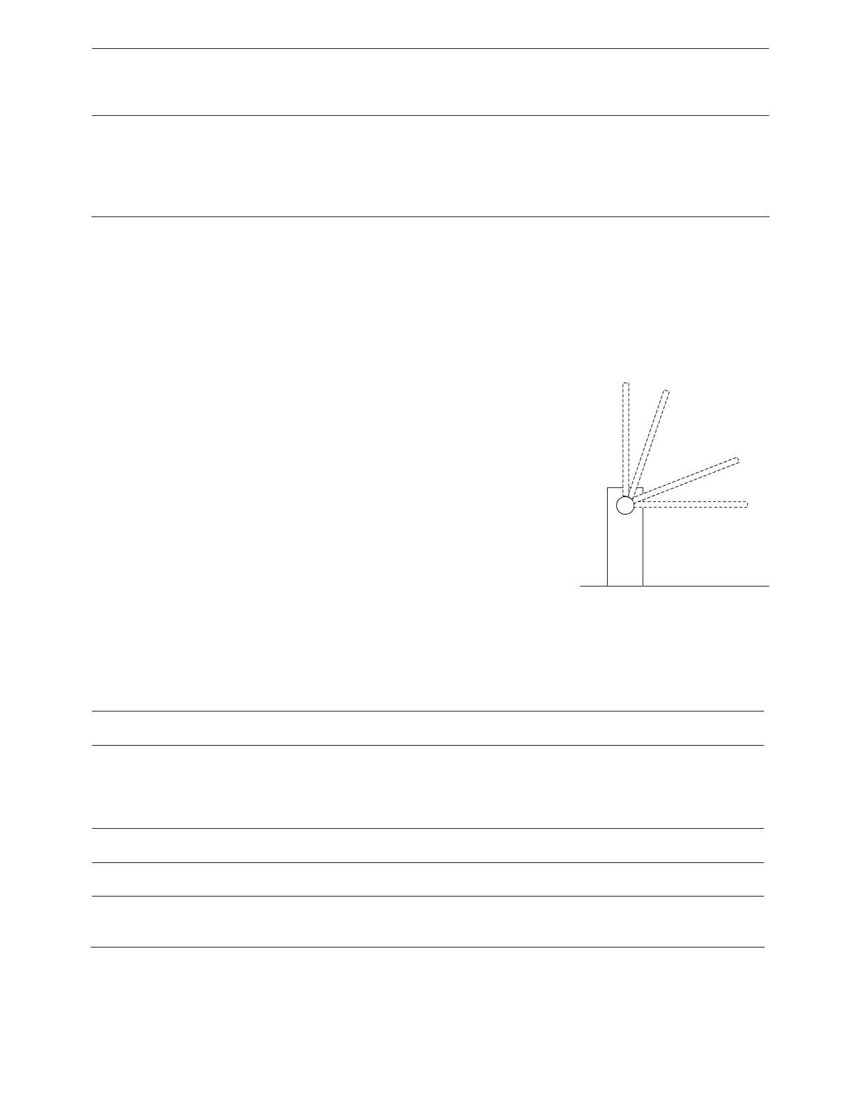
Position 0: this is the point at which the arm is in the closed condition,
corresponding to the closing stroke mechanical stop.
Position RC: this is the position at which the arm must start its deceleration
phase during the closing cycle.
Position RA: this is the position at which the arm must start its deceleration
phase during the opening cycle.
Position 1: this is the point at which the arm is in the fully open condition,
corresponding to the opening stroke mechanical stop.
4.1 Mechanical stops initial search
The "mechanical stops initial search" procedure is executed automatically as the first activation following
installation of the barrier.
To activate the mechanical stops initial search:
1. release the barrier, move it clear of the mechanical stops so that it is free to move in the opening and
closing directions, and then lock the barrier
2. briefly press the Close button on the board or generate a command pulse on the inputs and wait for the
control unit to perform a low speed closing to position 0, a low speed opening to position 1, and a high
speed closing to position 0.
Note if after transmitting the command the first movement is an opening, transmit a second command to
stop the procedure and then invert the polarity of the motor feeding wires.
3. When the sequence described above is concluded, a mathematical operation is executed to calculate the
deceleration positions (RA and RC) automatically.
4. The mechanical stops "initial search" procedure is now terminated and the gear motor is ready for use. Set
up the "functions" dip switches as required.
Note 1. If one of the safety devices should trip or another command pulse is received during the "initial
search" procedure, movement of the arm will be interrupted immediately; in this case the above procedure
must be repeated starting from step 1.
4.2 Mechanical stops automatic search
As an alternative to the "Initial search" procedure the "Mechanical stops automatic search" procedure can be
activated at any time without having to clear the memory. The procedure performs the mechanical stops
0
RA
RC
1
13
(positions 0 and 1) search procedure automatically using the same method as that described above for the
"Initial Search" procedure.
To activate the mechanical stops search
1. Set up the dip switches as shown:
12345678910 11 12
2. release the barrier, move it clear of the mechanical stops so that it is free to move in the opening and
closing directions, and then lock the barrier
3. Briefly press the Close button on the board and wait for the control unit to perform a low speed closing to
position 0, a low speed opening to position 1, and a high speed closing to position 0.
Note if after transmitting the command the first movement is an opening, transmit a second command to
stop the procedure and then invert the polarity of the motor feeding wires.
4. When the sequence described above is concluded, a mathematical operation is executed to calculate the
deceleration positions automatically.
5. Return the dip switches to the positions shown:
12345678910 11 12
6. The mechanical stops "automatic search" procedure is now terminated and the gear motor is ready for use.
Set up the "functions" dip switches as required.
Note 1. If one of the safety devices should trip or another command pulse is received during the
"automatic search procedure", movement of the arm will be interrupted immediately; in this case the
above procedure must be repeated starting from step 1.
4.3 Manual programming of deceleration positions.
This procedure involves the manual input of the positions for the start of deceleration as an alternative to the
positions calculated automatically with the initial or automatic mechanical stops search procedure.
To program the deceleration positions manually:
1. Set up the dip switches in accordance with one of the following diagrams depending on the parameter to
be saved
POSITION RC: Deceleration start position during the closing cycle
12345678910 11 12
POSITION RA: Deceleration start position during the opening cycle
12345678910 11 12
2. Press the Open or Close button on the board and hold it down until the required position has been
reached.
Note. Press the Stop button if you wish to accelerate movement of the bar.
3. Once the position has been reached release the buttons and execute the "Save procedure" (heading 4.4)
4. Return the dip switches to the positions shown:
12345678910 11 12
4.4 Save procedure
This operation serves to upload the value of the parameter you wish to program to the control unit permanent
memory.
14
To perform the save procedure:
1. Hold down the Stop button for at least 3 seconds, after which the OK LED will start flashing at high
frequency
2. Release the Stop button. The OK LED will continue to flash at high frequency for a further 3 seconds.
3. Within three seconds press the Open and Close buttons simultaneously and only momentarily; when the
two buttons are pressed simultaneously the OK LED will extinguish and then illuminate for 2 seconds to
confirm that the selected parameter has been correctly saved in the memory.
4.5 Memory delete
All programmable parameters are recorded in a non-volatile memory that retains the information also in the
event of a mains power loss; in certain cases it may prove necessary to remove all the data you have saved in
this memory.
To delete the contents of the memory:
1. Set the dip switches as shown:
12345678910 11 12
2.
Execute the "save procedure" (heading 4.4), which in this case is required to confirm the delete procedure.
3. Return the dip switches to the setting indicated
12345678910 11 12
Note. When the memory has been reset the system assumes the same status as when the control unit has never
been programmed so no movements will be possible; in this case the first command that is transmitted to the
inputs or pressing either the Open or Close buttons serves to activate a "Mechanical stops initial search"
procedure
Note 1. This operation does not delete the counter values for the number of cycles executed and the number of
cycles programmed.
4.6 Adjustments
When the programming phase is terminated you can make the small number of indispensable adjustments
necessary to ensure correct and safe operation of the automation system.
4.6.1 Torque adjustment
To limit the torque levels delivered by the transmission system in accordance with established standards, the
control unit is equipped with a trimmer (TR1) that serves to adjust motor torque. Turn the trimmer clockwise to
increase torque. If an obstacle is encountered during movement of the arm (motor torque demand higher than
programmed torque), the system will stop and, if a semiautomatic or automatic movement was in progress the
arm will reverse in the opposite direction. To increase safety levels, if the detection of an obstacle occurs three
times in succession before the bar has reached its correct closed position, the system will execute a brief
inversion of travel direction and then stop.
4.6.2 Speed adjustment
To limit the kinetic energy of the bar in the event of impact with possible obstacles, apart from restricting motor
torque it is also possible to reduce the speed of motion. The speed can be adjusted at any time by means of
trimmer TR2: turn the trimmer clockwise to increase speed. When the trimmer is set to the maximum speed
position barrier opening time is approximately 3 seconds; with the trimmer at its minimum speed position the
opening time is approximately 6 seconds.
4.6.3 Pause time adjustment
When the automatic closing function is selected, after an opening movement a timer is triggered (pause time);
when the timer interval elapses the close cycle is started automatically. Pause time can be adjusted by means of
trimmer TR3. With the trimmer in its minimum time position the pause time is 0 seconds; with the trimmer in
the maximum time position (fully clockwise) the pause time is 120 seconds.
15
5 Testing and commissioning
This is the most important operation, designed to guarantee the maximum safety and reliability of the
automation system. The testing procedure can also be used as a periodic check of the devices that
make up the automation.
Testing of the entire system must be performed by qualified and experienced personnel who must establish
which tests to conduct on the basis of the risks involved, and verify the compliance of the system with
applicable regulations, legislation and standards.
Each component of the system, e.g. the emergency stop device, photocells, etc. may require a specific testing
phase. We therefore recommend observing the procedures shown in the relative instruction manuals.
Execute the following steps for the testing procedure:
1. Ensure that the instructions outlined in the "WARNINGS" chapter have been observed in full.
2. Set the dip switches as shown:
(all functions disabled and semiautomatic operating mode)
12345678910 11 12
1. Press the Open button and check that:
the flashing light is activated
an opening cycle is started with the acceleration phase
the movement is decelerated and then stops when the arm is in the open position.
2. Press the Close button and check that:
the flashing light is activated
a closing cycle is started
the movement stops when the arm is closed.
3. Start an opening cycle and check that tripping of a safety device connected to the:
Stop input – causes immediate interruption of the movement
Photo input – has no effect
4. Start a closing cycle and check that tripping of a safety device connected to the:
Stop input – causes immediate interruption of the movement
Photo input – causes the movement to be stopped and restarted in the opposite direction
5. Engage a safety device connected to:
the Stop input, and check that when a command input is activated the system will not operate.
the Photo input, and check that when a close command input is activated the system will not operate.
6. During an opening or closing cycle, impede movement of the arm with an obstacle and check that the gear
motor performs a direction reversal before the torque level specified by applicable standards is exceeded.
7. Measure the impact force. If control of "motor torque" is used to assist the system for the reduction of
impact force, search for the setting that provides the best results
8. Check that the activation of the inputs (if connected) causes a step in the following sequence
for the Step-by-Step input: Open – Stop – Close – Stop,
for the Open input: Open – Stop – Open – Stop,
for the Close input: Close – Stop – Close – Stop
9. Return the dip switches to the setting indicated
12345678910 11 12
16
6 Selectable functions
To select the required functions set the programming dip switches to Off and activate the functions dip switches
as shown in the following list:
Switch 1-2 Off Off = "Manual" movement, i.e. hand operated
On Off = "Semiautomatic" function
Off On = "Automatic" function, i.e. Automatic Closing
On On = "Automatic + Always close" function
Switch 3 On = Condominium function <Not available in Manual mode>
Switch 4 On = 5 s preflashing (2 s in manual mode)
Switch 5 On = Re-close 0 s after Photo if in automatic mode or re-close after Photo if in
semiautomatic mode
Switch 6 On = Photo also during opening
Switch 7 On = Phototest activation
Switch 8 On
Off =
=Suction cup
Electric lock
Switch 9 On = Traffic light in one-way mode
Switch 10 On = Traffic light in both directions
Note. Setting dip switches to the "Off" position servers to inhibit the associated function.
6.1 Functions description
Man Present Function
The movement is performed only when the command is present. The movement stops as soon as the command
is suspended, when one of the safety devices trips ("Stop" or "Photo") or if the current sensor trips.
Once the cycle has been interrupted the input command must be deactivated before another command can be
transmitted to activate the arm.
Semiautomatic and automatic function
In "Semiautomatic" or “Automatic” mode following a command pulse the entire movement is executed until
the specified position is reached. A second pulse on the same input that started the movement will cause a
system Stop. If a control input is supplied with a continuous signal instead of a pulse, this will result in a
priority condition wherein all the other control inputs are disabled (this function is useful, for example, if a
clock is to be connected to the opening input). Tripping of the current sensor or a photocell involved in the
direction of motion during a cycle ("Photo" during the closing cycle) will result in a direction reversal.
In Automatic operating mode, an opening cycle will be followed by a pause and then a closing cycle. If the
"Photo" safety device trips during the pause interval, the timer will be reset with the preset pause time; if the
"Stop" input trips during the pause interval the re-close function will be cancelled and the system will assume
Stop status.
Always Close function
Automatically starts a close cycle preceded by 5 seconds of preflashing if "arm open" status is detected when
power is restored.
Condominium Function
In "Condominium" mode an opening cycle cannot be interrupted by control pulses except for those that result
in a closing cycle. During the closing cycle a new control pulse will cause the arm to reverse.
Preflashing
A command impulse activates the flashing light, followed by movement 5 seconds later (2 seconds later in
manual mode).
Re-close 0 seconds after Photo if in automatic mode or re-close after Photo if in semiautomatic mode
In automatic mode tripping of the photo safety device in the opening or closing cycle reduces the pause time to
0 seconds irrespective of the preset pause time. In semiautomatic mode tripping of the photo safety device
during the closing cycle activates automatic closing with the preset pause time.
Photo also during opening
With this function tripping of the "Photo" safety device causes an interruption of the movement also during the
opening cycle; if the "Semiautomatic" or "Automatic" function is selected, after the "Photo" device is
disengaged the opening cycle will be resumed.
Phototest activation
17
This function makes it possible to execute a check of the efficiency of all photocells at the start of every cycle,
thereby increasing the overall safety level of the system. For further details consult heading 3.9.
Suction cup/electric lock
The function makes it possible to assign the following type of operation to the Electric lock output (terminals 5
and 6):
electric lock (Switch 8 Off) – the output is activated for a few seconds in the opening cycle with the arm
closed
suction cup (Switch 8 On) – the output is activated at the end of the closing movement and it remains
activated for the entire time that the arm remains in the closed position.
Traffic light in one-way mode.
In this mode the SCA output is active with the arm open and during the opening cycle it remains switched on,
while it is deactivated when closing and with the arm closed. This makes it possible to connect a green traffic
light to the output to signal free transit when illuminated.
Traffic light in both directions.
Setting switch 10 to On, irrespective of the position of switch 9, serves to activate the function "Traffic light in
both directions"; the following changes occur in the control unit: the "Open" input becomes "Step-by-Step 2",
while the "Courtesy Light" (COR) and "Barrier open indicator light" (SCA) outputs become green traffic light
for one direction and green traffic light for the opposite direction as specified in Fig. 5. For each direction of
transit a different opening command is set: “Step-by-Step” (PP) to enter and “Step-by-Step 2” (PP2) to exit; in
this case two traffic lights are installed with Red and Green signals, connected to the SCA and COR outputs.
(COR) 13
V
V
R
R
V
(SCA) 12
R
R
V
11
Common
Command input with PP
Command output with PP2
Barrier open output - SCA
Courtesy light output - COR Barrier
In normal conditions the SCA and COR outputs are switched off and consequently also the traffic lights are
switched off; when a command is transmitted with PP to enter the protected area, the opening cycle is started
and simultaneously output SCA is activated and the green traffic light in the entry direction is activated together
with the red traffic light in the exit direction.
On the contrary, if the command for opening is given by PP2 the COR output is activated to activate the green
traffic light in the exit direction and the red traffic light in the entry direction. The light will remain illuminated
for the entire duration of the opening phase and during the pause phase, if programmed; in contrast, during the
closing phase the green and red lights will be illuminated together to signal that the transit priority situation is
no longer valid.
The two outputs can be used to drive low power 24 Vdc lamps for a maximum of 10 W per output. If higher
power lamps are required then it will be necessary to use relays driven by the control unit outputs to control the
traffic lights.
7 What to do if…
The following section describes some of the more common problems that may be encountered during
installation of the system.
No LED is on:
check for the presence of mains voltage on terminals 1 and 2 and ensure that fuses F1 and F3 are not blown.
The unit fails to start:
check that the Stop and Photo safety device input LEDs are active and the motor is locked (release LED
extinguished).
A direction reversal occurs during a cycle:
Check whether one of the safety devices has tripped (Photo during the closing cycle) or whether the current
sensor has tripped; in this latter case check that the current sensor setting is sufficiently high to allow
movement of the arm. If the value is insufficient increase the level by turning the torque trimmer (TR1) in a
clockwise direction.
18
High frequency flashing of the OK LED:
the power supply voltage is insufficient or an incorrect combination has been selected on the dip switches.
The motor moves slowly:
the control unit is executing an alignment procedure; the first trip of the current sensor is interpreted as a
mechanical stop.
The motor performs the acceleration phase and then stops:
check whether or not the encoder LED is flashing during movement of the motor. The flashing frequency
may be higher or lower in relation to the speed of movement. With the motor at a standstill the LED may be
On or Off, depending on the exact angular position at which the motor shaft has stopped.
OK LED steadily illuminated for a few seconds immediately after a command:
this indicates a fault in the motor control stage; check the wiring and ground insulation of the motor; if no
problems are found, install a new control unit.
8 Manual or release operation
Warning: the release operation must be performed only when the arm is stopped.
Manual operation
Fig. 12
must be adopted in the event of a power failure or in the case of system faults. The manual
operation will allow free movement of the arm only if installed correctly and with genuine original accessories.
1.
Lift the lock cover disk. Insert the key and turn it clockwise
2.
Turn the release handle counter-clockwise. Move the arm manually
To lock the arm: return the release handle to its original position, turn the key and extract it.
9 Maintenance
Maintenance operations must be performed in strict compliance with the safety directions provided in this
manual and in accordance with applicable legislation and standards. Although Signo does not require any
special maintenance operations, regular inspections carried out at programmed intervals will ensure longer life
of the system and reliable operation of the safety devices. For this purpose all the tests and checks specified in
heading 4.1 "Testing" should be performed.
If other devices are installed, adhere strictly to the directions given in the relative maintenance plan.
SIGNO 4 Perform a periodic general inspection every 6 months or 50,000 cycles
SIGNO 6 Perform a periodic general inspection every 6 months or 50,000 cycles
9.1 Planning of maintenance work
To assist planning of maintenance interventions for the entire system the control unit is equipped with a cycle
counter that increases its value at each opening cycle. The increase is signalled by a flash of the maintenance
LED (MAN). The cycles counter value is constantly compared to an alarm threshold value (programmable by
the system installer) and checked against a warning threshold (set automatically at approximately 6 % below
the alarm threshold). When the number of cycles executed exceeds the warning threshold the maintenance LED
flashes only during operation of the barrier, while if the alarm threshold is exceeded this LED flashes
constantly (when the motor is stopped and during movements) thereby signalling the urgent need for
maintenance.
The alarm threshold can be programmed from a minimum value of 1000 to a maximum of 255000 cycles in
multiples of 1000.
19
9.1 Alarm
To program the alarm threshold
1. Set the dip switches as shown
12345678910 11 12
2. Divide the number of cycles to be programmed by 1000
3. In the following table find the combination of dip switches
the sum of which is equivalent to the number you have just
calculated and set the relative dip switches to On.
Dip switch Sw1 Sw2 Sw3 Sw4 Sw5 Sw6 Sw7 Sw8
Pesi 1 2 4 8 16 32 64 128
Example: number of cycles to
be programmed = 100,000
Result after division: 100
100 = 4+ 32+64
dip switches 3, 6 and 7 set to
On
12345678910 11 12
4. Execute the "Save procedure" (heading 4.4).
5. Return the dip switches to the setting indicated
12345678910 11 12
After you have set the alarm threshold you can display it to be sure that the operation you have just performed
was successful.
To display the alarm threshold
1. Set the dip switches as shown:
12345678910 11 12
2. Set dip switch 1 to On (2,3,4,5 and 6 to Off), count the number of flashes of the OK LED and make a note
of them (if there were 10 flashes note down 0)
3. Repeat the operation with dip switches 2, 3, 4, 5 and 6
4. Now recalculate the number of cycles as shown in one of the two examples given below
Dip switch
configuration
123456
123456
123456
123456
123456
123456
Number
of cycles
Example:
no. 1
Number of OK
LED flashes 10 1 2 10 4 5 012,045
Example
n° 2 Number of OK
LED flashes 1 4 10 10 7 3 140,073
6. Return the dip switches to the setting indicated
12345678910 11 12
Use the same procedure to display the number of cycles executed;
To display the number of cycles executed
1. Set the dip switches as shown:
12345678910 11 12
2. Re-count the flashes of the OK LED with dip switches 1,2,3,4,5 and 6 as shown in example 1 or 2.
Note. Whenever the warning threshold is programmed the value for the number of cycles executed is
automatically deleted.
3. Return the dip switches to the setting indicated
12345678910 11 12
20
10 Disposal
SIGNO is constructed of various types of materials, some of which can be recycled (steel, aluminium, plastic,
electric cables), while others must be disposed of (electronic boards and components).
WARNING: some electronic components may contain polluting substances; do not pollute the environment.
Enquire about the recycling or disposal systems available in compliance with regulations locally in force.
1. Disconnect the automation system from the mains power supply.
2. Disassemble all the devices and accessories, following in reverse order the procedures described in
chapter 3 “Installation”
3. Remove the electronic board.
4. Sort the various electrical and recyclable materials and consign them to licensed firms for recovery and
disposal.
5. Consign the remaining materials to authorized scrap collection centres.
11 Technical specifications
SIGNO4 V1 SIGNO6 V1
* Without installed accessories
11.1 Control unit specifications
Services output : 24 Vdc, max. current 200mA (voltage can be between 17 and 35 Vdc)
Flashing light output : 24 Vdc, max. power 25W (voltage can be between 16 and 35 Vdc)
Electric lock output : 24 Vdc, max. current 250mA (voltage can be between 17 and 35 Vdc)
Phototest output : 24 Vdc, max. current 200mA (voltage can be between 17 and 35 Vdc)
Courtesy light output : 24 Vdc, max. power 10W (voltage can be between 17 and 35 Vdc)
Barrier open indicator light output : 24 Vdc, max. power 10W (voltage can be between 17 and 35 Vdc)
Maintenance indicator light output : 24 Vdc, max. power 10W (voltage can be between 17 and 35 Vdc)
STOP input: : for NC contacts or 8.2K constant resistance +/- 50%
Pause time : from 0 seconds to 120 seconds
Courtesy light time : 60 seconds
Max. cables length :
:power 100 ft
aerial 16 ft
Power supply (Vac 50/60 Hz) 110
Emergency power supply (Vdc) 24
Power draw (W) 300
Line current input (A) 2.6
Motor current input (A) 12
Transmission ratio 1 :241
Torque (Nm) 148 185
Min. – max. opening time (sec.) 3 - 6 6 - 10
Operating temperature (F Min./Max.) -4
0
/122
0
Duty cycle (%) 80
Protection rating 44
Weight (lbs) 110 128
Insulation class 1
  • Page 1 1
  • Page 2 2
  • Page 3 3
  • Page 4 4
  • Page 5 5
  • Page 6 6
  • Page 7 7
  • Page 8 8
  • Page 9 9
  • Page 10 10
  • Page 11 11
  • Page 12 12
  • Page 13 13
  • Page 14 14
  • Page 15 15
  • Page 16 16
  • Page 17 17
  • Page 18 18
  • Page 19 19
  • Page 20 20
  • Page 21 21
  • Page 22 22

HySecurity Nice Signo Owner's manual

Type
Owner's manual

HySecurity Nice Signo is an electromechanical barrier operator designed for automating access points with barrier arms up to 12 or 20 feet in length. It features precise motor control with deceleration at stroke limits and obstacle detection for enhanced safety. SIGNO can operate in manual, semi-automatic, and automatic modes, with configurable functions such as automatic closing, traffic light signaling, and a cycle counter for maintenance scheduling. Optional accessories are available to expand its functionality.

Ask a question and I''ll find the answer in the document

Finding information in a document is now easier with AI