Sony STR-DN610 User manual

Category
AV receivers
Type
User manual
model name1[STR-DN610]
[4-167-824-13(1)]
filename[D:\NORM'S JOB\SONY HA\SO0086\STR-DN610_PMRF 2\GB\GB01COV_STR-DN610-U2.fm] masterpage:Right
©2010 Sony Corporation
4-167-824-13(1)
Multi Channel AV
Receiver
Operating Instructions
STR-DN610
2GB
D:\NORM'S JOB\SONY HA\SO0086\STR-DN610_PMRF 2\GB\GB02REG_STR-DN610-U2.fm4-
167-824-13(1)
masterpage: Left
STR-DN610
4-167-824-13(1)
To reduce the risk of fire or electric
shock, do not expose this apparatus to
rain or moisture.
To reduce the risk of fire, do not cover the
ventilation opening of the apparatus with
newspapers, tablecloths, curtains, etc. Do not place
the naked flame sources such as lighted candles on
the apparatus.
Do not install the appliance in a confined space, such
as a bookcase or built-in cabinet.
To reduce the risk of fire or electric shock, do not
expose this apparatus to dripping or splashing, and
do not place objects filled with liquids, such as
vases, on the apparatus.
As the main plug is used to disconnect the unit from
the mains, connect the unit to an easily accessible
AC outlet. Should you notice an abnormality in the
unit, disconnect the main plug from the AC outlet
immediately.
Do not expose batteries or apparatus with battery-
installed to excessive heat such as sunshine, fire or
the like.
The unit is not disconnected from the mains as long
as it is connected to the AC outlet, even if the unit
itself has been turned off.
Excessive sound pressure from earphones and
headphones can cause hearing loss.
This symbol is intended to alert
the user to the presence of the Hot
Surface that may be hot if it is
touched during the normal
operation.
For customers in Europe
Disposal of Old Electrical &
Electronic Equipment
(Applicable in the European
Union and other European
countries with separate
collection systems)
This symbol on the product or on its packaging
indicates that this product shall not be treated as
household waste. Instead it shall be handed over to
the applicable collection point for the recycling of
electrical and electronic equipment. By ensuring this
product is disposed of correctly, you will help
prevent potential negative consequences for the
environment and human health, which could
otherwise be caused by inappropriate waste
handling of this product. The recycling of materials
will help to conserve natural resources. For more
detailed information about recycling of this product,
please contact your local Civic Office, your
household waste disposal service or the shop where
you purchased the product.
WARNING
3GB
D:\NORM'S JOB\SONY HA\SO0086\STR-DN610_PMRF 2\GB\GB02REG_STR-DN610-U2.fm masterpage: Right
STR-DN610
4-167-824-13(1)
Disposal of waste batteries
(applicable in the European
Union and other European
countries with separate
collection systems)
This symbol on the battery or on the packaging
indicates that the battery provided with this product
shall not be treated as household waste.
On certain batteries this symbol might be used in
combination with a chemical symbol. The chemical
symbols for mercury (Hg) or lead (Pb) are added if
the battery contains more than 0.0005% mercury or
0.004% lead.
By ensuring these batteries are disposed of correctly,
you will help prevent potentially negative
consequences for the environment and human health
which could otherwise be caused by inappropriate
waste handling of the battery. The recycling of the
materials will help to conserve natural resources.
In case of products that for safety, performance or
data integrity reasons require a permanent
connection with an incorporated battery, this battery
should be replaced by qualified service staff only.
To ensure that the battery will be treated properly,
hand over the product at end-of-life to the applicable
collection point for the recycling of electrical and
electronic equipment.
For all other batteries, please view the section on
how to remove the battery from the product safely.
Hand the battery over to the applicable collection
point for the recycling of waste batteries.
For more detailed information about recycling of
this product or battery, please contact your local
Civic Office, your household waste disposal service
or the shop where you purchased the product.
Notice for customers: The following
information is only applicable to
equipment sold in the countries
applying EU Directives.
The manufacturer of this product is Sony
Corporation, 1-7-1 Konan Minato-ku Tokyo,
108-0075 Japan. The Authorized Representative for
EMC and product safety is Sony Deutschland
GmbH, Hedelfinger Strasse 61, 70327 Stuttgart,
Germany. For any service or guarantee matters
please refer to the addresses given in separate
service or guarantee documents.
About This Manual
The instructions in this manual are for model
STR-DN610. Check your model number by
looking at the lower right corner of the front panel.
In this manual, models of area code ECE is used
for illustration purposes unless stated otherwise.
Any difference in operation is clearly indicated in
the text, for example, “Models of area code ECE
only”.
The instructions in this manual describe the
controls on the supplied remote. You can also use
the controls on the receiver if they have the same
or similar names as those on the remote.
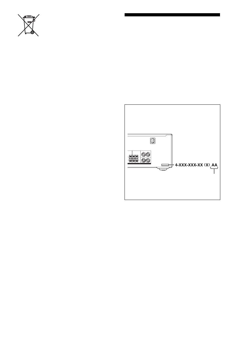
About area codes
The area code of the receiver you purchased is
shown on the lower right portion of the rear panel
(see the illustration below).
Any differences in operation, according to the area
code, are clearly indicated in the text, for example,
“Models of area code AA only”.
LR
R
L
FRONT A
CENTER SURROUND
SPEAKERS IMPEDANCE USE 8-16
Area code
4GB
D:\NORM'S JOB\SONY HA\SO0086\STR-DN610_PMRF 2\GB\GB02REG_STR-DN610-U2.fm4-
167-824-13(1)
masterpage: Left
STR-DN610
4-167-824-13(1)
This receiver incorporates Dolby* Digital and Pro
Logic Surround and the DTS** Digital Surround
System.
* Manufactured under license from Dolby
Laboratories. Dolby, Pro Logic, and the double-
D symbol are trademarks of Dolby Laboratories.
** Manufactured under license under U.S. Patent
#’s: 5,451,942; 5,956,674; 5,974,380; 5,978,762;
6,226,616; 6,487,535; 7,003,467; 7,212,872 &
other U.S. and worldwide patents issued &
pending. DTS, DTS Digital Surround, ES, and
Neo:6 are registered trademarks and the DTS
logos, Symbol and DTS 96/24 are trademarks of
DTS, Inc. © 1996-2008 DTS, Inc. All Rights
Reserved.
This receiver incorporates High-Definition
Multimedia Interface (HDMITM) technology.
HDMI, the HDMI Logo, and High-Definition
Multimedia Interface are trademarks or registered
trademarks of HDMI Licensing LLC in the United
States and other countries.
“x.v.Color (x.v.Colour)” and “x.v.Color
(x.v.Colour)” logo are trademarks of Sony
Corporation.
“BRAVIA” is a trademark of Sony Corporation.
“PLAYSTATION” is a trademark of Sony
Computer Entertainment Inc.
On Copyrights
5GB
D:\NORM'S JOB\SONY HA\SO0086\STR-DN610_PMRF 2\GB\GB01COV_STR-DN610-
U2TOC.fm
masterpage: Right
STR-DN610
4-167-824-13(1)
Table of Contents
About This Manual........................................3
Supplied accessories......................................6
Description and location of parts...................7
Connections
1: Installing the speakers .............................16
2: Connecting the speakers..........................18
3: Connecting the TV ..................................20
4a: Connecting the audio components.........21
4b: Connecting the video components ........23
5: Connecting the antennas (aerials)............30
6: Connecting the AC power cord
(mains lead) ............................................30
Preparing the Receiver
Initializing the receiver................................31
Selecting the speaker system .......................31
Calibrating the appropriate speaker settings
automatically
(AUTO CALIBRATION).......................32
Adjusting the speaker levels
(TEST TONE) ........................................36
Basic Operations
Playback ......................................................37
Viewing information on the display ............38
Using the Sleep Timer .................................39
Recording ....................................................39
Tuner Operations
Listening to FM/AM radio ..........................40
Presetting FM/AM radio stations ................42
Using the Radio Data System (RDS) ..........44
(Models of area code CEK, ECE only)
Enjoying Surround Sound
Selecting the sound field............................. 44
Enjoying the surround effect at low volume
levels (NIGHT MODE) ......................... 49
Resetting sound fields to the initial
settings ................................................... 49
“BRAVIA” Sync Features
What is “BRAVIA” Sync? .......................... 50
Preparing for the “BRAVIA” Sync ............. 50
Playing back components with one-touch
operation (One-Touch Play)................... 51
Enjoying the TV sound from the speakers
connected to the receiver
(System Audio Control)......................... 52
Turning off the receiver with the TV
(System Power Off) ............................... 53
Enjoying movies with the optimum sound
field (Theater/Theatre Mode Sync)........ 54
Enjoying the TV sound via an HDMI cable
(Audio Return Channel)......................... 54
Advanced Operations
Switching between digital and analog audio
(INPUT MODE) .................................... 55
Enjoying the sound/images from other
inputs...................................................... 55
Enjoying sound/images from the components
connected to the DIGITAL MEDIA
PORT ..................................................... 57
Using a bi-amplifier connection.................. 57
Using the setting menu ............................... 58
Using the Remote
Changing the input button assignments ...... 69
Clearing all the contents of the remote’s
memory .................................................. 70
continued
6GB
D:\NORM'S JOB\SONY HA\SO0086\STR-DN610_PMRF 2\GB\GB01COV_STR-DN610-
U2TOC.fm
masterpage: Left
STR-DN610
4-167-824-13(1)
Additional Information
Glossary.......................................................71
Precautions ..................................................73
Troubleshooting...........................................74
Specifications...............................................79
Index ............................................................81
Supplied accessories
Operating instructions (this manual)
Quick Setup Guide
FM wire antenna (aerial) (1)
AM loop antenna (aerial) (1)
Remote commander (1)
– RM-AAU073 (Models of area code CA2
only)
– RM-AAU075 (Models of area code CEK,
ECE only)
R6 (size-AA) batteries (2)
Optimizer microphone (ECM-AC2) (1)
7GB
D:\NORM'S JOB\SONY HA\SO0086\STR-DN610_PMRF 2\GB\GB03DES_STR-DN610-U2.fm masterpage: Right
STR-DN610
4-167-824-13(1)
Description and location of parts
A?/1 (on/standby) (page 31)
BRemote sensor
Receives signals from remote commander.
CWhite lamp
Lights up when the receiver is on.
Lights off when the receiver is off.
DDisplay (page 8)
EMUTING (page 37)
FINPUT SELECTOR +/– (page 37, 55)
GMASTER VOLUME (page 36, 37)
HVIDEO 2 IN jacks (page 29)
IAUTO CAL MIC jack (page 33)
JDISPLAY (page 38)
KDIMMER (page 69)
LINPUT MODE (page 55)
M2CH/A.DIRECT, A.F.D., MOVIE, MUSIC
(page 44)
NSPEAKERS (page 31)
OPHONES jack (page 75)
Front panel
?/1
123 4 6 7
890
5
qaqsqf qdqg
8GB
D:\NORM'S JOB\SONY HA\SO0086\STR-DN610_PMRF 2\GB\GB03DES_STR-DN610-U2.fm masterpage: Left
STR-DN610
4-167-824-13(1)
Indicators on the display
LFE
NEO:6
LC
SL S
PL II x
HDMI -ESDTS 96/24
SLEEP
D.RANGEST
RDS
COAX OPT LPCM
SW
SB
SBL
R
SR
SBR
D EX
qs qa q;
12 3 4 5697 8
Indicator and explanation
ASW
Lights up when the audio signal is output from
the SUBWOOFER jack.
B
Lights up when the disc being played back
contains an LFE (Low Frequency Effect)
channel and the LFE channel signal is actually
being reproduced.
CInput indicators
Light up to indicate the current input.
HDMI
Lights up when
the receiver recognizes a component
connected via an HDMI IN jack (page 23).
TV input detected Audio Return Channel
(ARC) signals (page 54).
COAX
Lights up when INPUT MODE is set to
“AUTO” (page 55) and the source signal is a
digital signal being input through the
COAXIAL jack.
OPT
Lights up when INPUT MODE is set to
“AUTO” (page 55) and the source signal is a
digital signal being input through the OPTICAL
jack.
LFE
Indicator and explanation
DDTS(-ES) indicators
Light up when DTS signals are input.
DTS
Lights up when the receiver is decoding DTS
signals.
DTS-ES
Lights up when the receiver is decoding DTS-
ES signals.
DTS 96/24
Lights up when the receiver is decoding DTS
96 kHz/24 bit signals.
Note
When playing a DTS format disc, be sure that
you have made digital connections and that
INPUT MODE is set to “AUTO” (page 55).
ENEO:6
Lights up when DTS Neo:6 Cinema/Music
decoder is activated (page 45).
FLPCM
Lights up when Linear PCM (Pulse Code
Modulation) signals are detected.
GDolby Pro Logic indicators
Light up one of the respective indicators when
the receiver performs Dolby Pro Logic
processing. This matrix surround decoding
technology can enhance input signals.
PL
PL II
PL IIx
Dolby Pro Logic
Dolby Pro Logic II
Dolby Pro Logic IIx
Note
These indicators may not light up depending on
the speaker pattern setting.
9GB
D:\NORM'S JOB\SONY HA\SO0086\STR-DN610_PMRF 2\GB\GB03DES_STR-DN610-U2.fm masterpage: Right
STR-DN610
4-167-824-13(1)
Indicator and explanation
HDolby Digital Surround indicators
Light up one of the respective indicators when
the receiver is decoding the corresponding
Dolby Digital format signals.
D
D EX
Dolby Digital
Dolby Digital Surround EX
Note
When playing a Dolby Digital format disc, be
sure that you have made digital connections and
that INPUT MODE is set to “AUTO” (page 55).
ISLEEP
Lights up when the sleep timer is activated (page
39).
JD.RANGE
Lights up when dynamic range compression is
activated (page 62).
KTuning indicators
Light up when the receiver tunes in radio
stations.
ST
Stereo broadcast
RDS (Models of area code CEK, ECE
only)
A station that provides RDS services is tuned in.
Preset station number.
Note
The preset station number will change
according to the preset station you select. For
details on presetting radio stations, see page 42.
Indicator and explanation
LPlayback channel indicators
The letters (L, C, R, etc.) indicate the channels
being played back. The boxes around the letters
vary to show how the receiver downmixes or
upmixes the source sound (based on the speaker
settings).
L
R
C
SL
SR
S
SBL
SBR
SB
Front Left
Front Right
Center (monaural)
Surround Left
Surround Right
Surround (monaural or the
surround components obtained
by Pro Logic processing)
Surround Back Left
Surround Back Right
Surround Back (the surround
back components obtained by
6.1 channel decoding)
Example:
Speaker pattern: 3/0.1
Recording format: 3/2.1
Sound Field: A.F.D. AUTO
LC
SL
SW
R
SR
LFE
10GB
D:\NORM'S JOB\SONY HA\SO0086\STR-DN610_PMRF 2\GB\GB03DES_STR-DN610-U2.fm masterpage: Left
STR-DN610
4-167-824-13(1)
* You can watch the selected input image when you
connect the HDMI TV OUT or MONITOR OUT
jack to a TV (page 20, 23).
Rear panel
LR
LR
R
L
FRONT A
CENTER SURROUND
ANTENNA
TV OUT1 NI2 NI3 NI
HDMI ASSIGNABLE (INPUT ONLY)
ARC
TV
IN
OPTICAL
SAT/
CATV
IN
OPTICAL
DVD
IN
DIGITAL
COAXIAL
(ASSIGNABLE)
DMPORT
DC5V
0.7A MAX
P
B
/
C
B
P
R
/
C
R
Y
IN 3 IN 2 IN 1
MONITOR
OUT
COMPONENT VIDEO
ASSIGNABLE (INPUT ONLY)
VIDEO
IN
VIDEO
IN
VIDEO
OUT
VIDEO
IN
MONITOR
VIDEO
OUT
AUDIO
IN
AUDIO
OUT
AUDIO
IN
BD
SAT/CATV
AUDIO
IN
AUDIO
IN
SA-CD/CD/CD-R
R
VIDEO 1
L
AUDIO
IN
AUDIO
OUT
AUDIO
OUT
TV
SUBWOOFER
SPEAKERS
IMPEDANCE USE 8-16
121,223
5 1 4
AAudio signal section
DIGITAL INPUT/OUTPUT jacks (page 20,
23, 26, 27, 28)
HDMI IN/OUT
OPTICAL IN
COAXIAL IN
ANALOG INPUT/OUTPUT jacks (page 18,
20, 21, 26, 28, 29)
AUDIO
IN/OUT
AUDIO OUT
White (L)
Red (R)
Black
BVideo signal section*
The image quality depends on the connecting
jack.
DIGITAL INPUT/OUTPUT
jacks (page 20, 23)
HDMI IN/OUT
COMPONENT VIDEO
INPUT/OUTPUT jacks (page
20, 26, 27, 28)
Y, PB/CB, PR/CR
IN/OUT
COMPOSITE VIDEO INPUT/
OUTPUT jacks (page 20, 26,
28, 29)
VIDEO IN/OUT
High
quality
image
Green
(Y)
Blue
(PB/CB)
Red
(PR/CR)
Yellow
11GB
D:\NORM'S JOB\SONY HA\SO0086\STR-DN610_PMRF 2\GB\GB03DES_STR-DN610-U2.fm masterpage: Right
STR-DN610
4-167-824-13(1)
You can use the supplied remote
RM-AAU073 (Models of area code CA2 only)
or RM-AAU075 (Models of area code CEK,
ECE only) to operate the receiver and to
control the Sony audio/video components that
the remote is assigned to operate.
CANTENNA section (page 30)
FM ANTENNA jack
AM ANTENNA terminals
DSPEAKERS section (page 18)
EDMPORT section (page 21)
DMPORT jack
Remote commander
.
mM
>
Xx
BD DVD SAT/
CATV
VIDEO1 VIDEO2
SA-CD/
CD DMPORT TUNER
MENU
O
TV
HDMI 2 HDMI 3HDMI 1
qh
qj
qk
ql
wf
wg
ws
wd
w;
wa
1
2
3
4
6
0
8
7
9
qs
qd
qf
qg
5
qa
continued
12GB
D:\NORM'S JOB\SONY HA\SO0086\STR-DN610_PMRF 2\GB\GB03DES_STR-DN610-U2.fm masterpage: Left
STR-DN610
4-167-824-13(1)
Notes on using the SHIFT (O)
and TV (P) button
SHIFT (O) button
Press and hold SHIFT (O), then press the
button with pink printing that you want to use.
Example: Press and hold SHIFT (O), then
press ENTER (C).
TV (P) button
Press and hold TV (P), then press the button
with yellow printing to control the TV.
Example: Press and hold TV (P), then press
TV CH + (RM-AAU073 only) or PROG +
(RM-AAU075 only) (N).
To control the receiver
SHIFT
.
mM
>
Xx
SA-CD/
CD DMPORT TUNER
MENU
O
HDMI 2 HDMI 3HDMI 1
ENTER
Name and function
B?/1b) (on/standby)
Turns the receiver on or sets it to standby mode.
Saving the power in standby mode
When “CTRL.HDMI” is set to “CTRL OFF”
(page 61).
CInput buttons (VIDEO 1a))
Selects the component you want to use. When
you press any of the input buttons, the receiver
turns on. The buttons are initial assigned to
control Sony components.
Numeric buttonsc) (number 5a))
Presets or tunes to preset stations.
ENTERc)
Enters the selections.
DD.TUNING
Enters direct tuning mode.
EMEMORY
Stores a station during tuner operation.
FDISPLAY
Views information on the display.
IAMP MENU
Displays the menu to operate the receiver.
J
Press V/v/B /b to select the settings, then press
to enter the selection.
LMENU/HOMEd)
Displays the menu to operate the receiver.
.>
Xx
TV CH / PROG
TV
,V/v/B/b
13GB
D:\NORM'S JOB\SONY HA\SO0086\STR-DN610_PMRF 2\GB\GB03DES_STR-DN610-U2.fm masterpage: Right
STR-DN610
4-167-824-13(1)
a)The following buttons have tactile dots:
RM-AAU073: 5/VIDEO 1, AUDIO, N and
TV CH +/SOUND FIELD +
RM-AAU075: 5/VIDEO 1, , N and
PROG +/SOUND FIELD +/c
Use the tactile dots as references when operating
the receiver.
b)If you press AV ?/1 (A) and ?/1 (B)
simultaneously, the receiver and connected
components will turn off (SYSTEM STANDBY).
c)Press and hold SHIFT (O) then press this button.
d)Press AMP MENU (I) to activate this button.
To control a Sony TV
Press and hold TV (P) and then press the
yellow printing button to select the function
you want.
Name and function
MTUNING +/–
Scans a station.
PRESET +/–
Selects preset stations.
NSOUND FIELD +a)/–
Selects a sound field.
QMASTER VOL +/– (RM-AAU073 only)
+/– (RM-AAU075 only)
Adjust the volume level of all speakers at the
same time.
RMUTING (RM-AAU073 only)
(RM-AAU075 only)
Turns off the sound temporarily.
Press MUTING/ again to restore the sound.
SRETURN/EXIT O
Returns to the previous menu.
Name and function
ATV ?/1 (on/standby)
Turns the TV on or off.
CNumeric buttons (number 5a))
Selects the TV channels.
ENTER (RM-AAU073 only)
Enters the selections.
(Previous channel) (RM-AAU075
only)
Returns to the previous channel watched (for
more than five seconds).
/ (Text) (RM-AAU075 only)
Displays text.
FDISPLAY (RM-AAU073 only)
Displays the information of TV.
/ (Info/Text reveal)
(RM-AAU075 only)
In digital mode: Displays brief details of the
program currently being watched.
In analog mode: Displays information such as
current channel number and screen format.
In text mode: Reveals hidden information (e.g.
answers to a quiz).
HColor buttons
Displays an operation guide on the TV screen
when the color buttons are available. Follow the
operation guide to perform a selected operation.
KTOOLS/OPTIONS
Displays the TV options.
LMENU/HOME
Displays the TV menus.
NTV CH +a)/– (RM-AAU073 only)
Selects the next (+) or previous (–) channel.
PROG +a)/–, ca)/C (RM-AAU075 only)
In TV mode: Selects the next (+) or previous
(–) channel.
In text mode: Selects the next (c) or previous
(C) channel.
QTV VOL +/– (RM-AAU073 only)
+/– (RM-AAU075 only)
Adjusts the volume.
RMUTING (RM-AAU073 only)
(RM-AAU075 only)
Activates the TV’s muting function.
continued
14GB
D:\NORM'S JOB\SONY HA\SO0086\STR-DN610_PMRF 2\GB\GB03DES_STR-DN610-U2.fm masterpage: Left
STR-DN610
4-167-824-13(1)
a)The following buttons have tactile dots.
RM-AAU073: 5/VIDEO 1, AUDIO, N and
TV CH +/SOUND FIELD +
RM-AAU075: 5/VIDEO 1, , N and
PROG +/SOUND FIELD +/c
Use the tactile dots as references when operating
the receiver.
Name and function
SRETURN/EXIT O
Returns to the previous TV menu.
TGUIDE (RM-AAU073 only)
(RM-AAU075 only)
Displays the guide when you are watching
analog or digital channel.
VAUDIOa) (RM-AAU073 only)
a) (RM-AAU075 only)
Selects the desired audio signal.
WDIGITAL (RM-AAU075 only)
Changes to digital mode.
ANALOG (RM-AAU075 only)
Changes to analog mode.
XTHEATER (RM-AAU073 only)
THEATRE (RM-AAU075 only)
Sets the optimal picture settings automatically
for watching movies when you connect a Sony
TV that is compatible with the THEATER/
THEATRE button function (page 54).
YINPUT (RM-AAU073 only)
Selects the input signal (TV or video).
/ (Input select/Text hold)
(RM-AAU075 only)
In TV mode: Selects the input signal (TV or
video).
In analog text mode: Holds the current page.
15GB
D:\NORM'S JOB\SONY HA\SO0086\STR-DN610_PMRF 2\GB\GB03DES_STR-DN610-U2.fm masterpage: Right
STR-DN610
4-167-824-13(1)
To control other Sony components
a)The following buttons have tactile dots.
RM-AAU073: 5/VIDEO 1, AUDIO, N and
TV CH +/SOUND FIELD +
RM-AAU075: 5/VIDEO 1, , N and
PROG +/SOUND FIELD +/c
Use the tactile dots as references when operating
the receiver.
b)If you press AV ?/1 (A) and ?/1 (B)
simultaneously, the receiver and connected
components will turn off (SYSTEM STANDBY).
The function of the AV ?/1 (A) changes
automatically each time you press the input
buttons (C).
c)Press and hold SHIFT (O) then press this button.
d)RM-AAU073 only.
e) RM-AAU075 only.
f) This button is also available for DIGITAL MEDIA
PORT adapter operation. For details on the
function of the button, refer to the operating
instructions supplied with the DIGITAL MEDIA
PORT adapter.
Notes
Some functions explained in this section may not
work depending on the model.
The above explanation is intended to serve as an
example only. Therefore, depending on the
component, the above operation may not be
possible or may operate differently than described.
Name Blu-ray disc,
DVD player
Satellite tuner,
cable TV tuner
VCR CD player
AAV ?/1b) Power Power Power Power
CNumeric buttonsc)
(number 5a))
Track Channel Channel Track
ENTERc) Enter Enterd) Enter Enter
CLEARc) Clear Clear –
FDISPLAY Display Display Display Display
GANGLEd)
e)
Select angle
HColor buttons Menu, guide Menu, guidee) ––
JEnter Enter Enter –
V/v/B/bSelect Select Select –
KTOOLS/OPTIONS Options menu Options menud) ––
LMENU/HOME Menu Menu Menu –
Mm/Mf) Search forward,
backward
Fast forward,
rewind
Fast forward,
rewind
Na)f) Play – Play Play
./>f) Skip track Skip track Skip track
Xf) Pause – Pause Pause
xf) Stop – Stop Stop
SRETURN/
EXIT O
Exit menu Exit menu,
Live TVd) ––
TGUIDEd)
e)
Program schedule Display guide
menu
––
USUBTITLEd)
e)
Select subtitle
VAUDIOa)d)
a)e)
Select audio
WTOP MENU On-screen guide
POP UP/MENU Menu–––
continued
16GB
D:\NORM'S JOB\SONY HA\SO0086\STR-DN610_PMRF 2\GB\GB04CON_STR-DN610-U2.fm masterpage: Left
STR-DN610
4-167-824-13(1)
Inserting batteries into the
remote
Insert two R6 (size-AA) batteries in the
RM-AAU073 (Models of area code CA2 only)
or RM-AAU075 (Models of area code CEK,
ECE only) Remote Commander.
Observe the correct polarity when installing
batteries.
Notes
Do not leave the remote in an extremely hot or
humid place.
Do not use a new battery with old ones.
• Do not mix manganese batteries and other kinds of
batteries.
Do not expose the remote sensor to direct sunlight
or lighting apparatuses. Doing so may cause a
malfunction.
If you do not intend to use the remote for an
extended period of time, remove the batteries to
avoid possible damage from battery leakage and
corrosion.
• When you replace the batteries, the remote buttons
may be reset to their initial settings. If this happens,
reassign the button again (page 69).
When the remote no longer operates the receiver,
replace all the batteries with new ones.
1: Installing the speakers
This receiver allows you to use a 7.1 channel
system (7 speakers and one subwoofer).
To fully enjoy theater-like multi channel
surround sound requires five speakers (two
front speakers, a center speaker, and two
surround speakers) and a subwoofer (5.1
channel).
You can enjoy high fidelity reproduction of
DVD software recorded sound in the Surround
EX format if you connect additional one
surround back speaker (6.1 channel) or two
surround back speakers (7.1 channel).
Example of speaker system
configuration
AFront speaker (left)
BFront speaker (right)
CCenter speaker
DSurround speaker (left)
ESurround speaker (right)
FSurround back speaker (left)
GSurround back speaker (right)
HSubwoofer
Connections
17GB
D:\NORM'S JOB\SONY HA\SO0086\STR-DN610_PMRF 2\GB\GB04CON_STR-DN610-U2.fm masterpage: Right
STR-DN610
4-167-824-13(1)
Connections
Note
To enjoy better surround sound, the distance
between the center speaker and the listening position
B cannot be more than 1.5 meters (5 feet) closer
than the one between the listening position and the
front speaker A. Place the speakers so that the
difference in the length of B in the following
diagram is no more than 1.5 meters (5 feet) closer
than the length of A.
Example: Adjust the distance B to 4.5 meters
(15 feet) or more when the distance A is 6 meters
(20 feet).
Also, the distance between the surround speakers/
surround back speakers and the listening position
C cannot be more than 4.5 meters (15 feet) closer
than the distance between the listening position and
the front speakers A. Place the speakers so that the
difference in the length of C in the following
diagram is no more than 4.5 meters (15 feet) closer
than the length of A.
Example: Adjust the distance C to 1.5 meters
(5 feet) or more when the distance A is 6 meters
(20 feet).
This is important because incorrect speaker
placement is not conductive to the enjoyment of
surround sound. Please note that placing the
speakers closer than the required will cause a delay
in the output of the sound from that speaker. In other
words, the speaker will sound like it is farther away.
Adjusting these parameter while listening to the
sound often results in much better surround sound.
Tips
When you connect a 7.1 channel speaker system
with two surround back speakers, all angle A
should be the same.
When you connect a 6.1 channel speaker system,
place the surround back speaker behind the
listening position.
Since the subwoofer does not emit highly
directional signals, you can place it wherever you
want.
18GB
D:\NORM'S JOB\SONY HA\SO0086\STR-DN610_PMRF 2\GB\GB04CON_STR-DN610-U2.fm masterpage: Left
STR-DN610
4-167-824-13(1)
2: Connecting the speakers
Before connecting the cords, be sure to disconnect the AC power cord (mains lead).
10 mm
(13/32")
LR
R
L
TV OUT1 NI2 NI
HDMI ASSIGNABLE (INPUT ONLY)
ARC
VIDEO
OUT
VIDEO
IN
MONITOR
VIDEO
OUT
AUDIO
IN
AUDIO
OUT
VIDEO 1
AUDIO
OUT
SPEAKERS
IMPEDANCE USE 8-16
RL
CENTER SURROUND FRONT A
SUBWOOFER
Right
B
Left
Right
AMonaural audio cord (not supplied)
BSpeaker cord (not supplied)
LeftRight
Center speaker
B
Left
B
B
Front A speakerSurround back/
Bi-amplifier/Front B
speaker
a)
Surround speaker
Subwoofer b)
A
19GB
D:\NORM'S JOB\SONY HA\SO0086\STR-DN610_PMRF 2\GB\GB04CON_STR-DN610-U2.fm masterpage: Right
STR-DN610
4-167-824-13(1)
Connections
a)Notes on the SPEAKERS SURROUND BACK/
BI-AMP/FRONT B terminals connection.
If you connect only one surround back speaker,
connect it to the L of this terminals.
If you are not using surround back speaker, and
you have an additional front speaker system,
connect the additional front speaker system to
this terminals.
Set “SB ASGN” to “SPK B” in the SPEAKER
menu (page 65).
You can select the front speaker system you
want to use with the SPEAKERS button on the
receiver (page 31).
If you are not using surround back speaker, you
can connect the front speakers to this terminals
using bi-amplifier connection (page 19).
b)When you connect a subwoofer with an auto
standby function, turn off the function when
watching movies. If the auto standby function is
set to on, it turns to standby mode automatically
based on the level of the input signal to a
subwoofer, then sound may not be output.
Notes
Before connecting the AC power cord (mains
lead), make sure that metalic wires of the speaker
cords are not touching each other between the
SPEAKERS terminals.
• After you have install and connect your speaker, be
sure to select the speaker pattern from SPEAKER
menu (page 63).
If you are not using surround back speakers,
you can connect the front speakers to the
SPEAKERS SURROUND BACK/BI-AMP/
FRONT B terminals using a bi-amplifier
connection.
Connect the jacks on the Lo (or Hi) side of the
front speakers to the SPEAKERS FRONT A
terminals, and connect the jacks on the Hi (or
Lo) side of the front speakers to the
SPEAKERS SURROUND BACK/BI-AMP/
FRONT B terminals.
Make sure that metal fittings of Hi/Lo attached
to the speakers have been removed from the
speakers. Not doing so may cause a
malfunction of the receiver.
After you have made the bi-amplifier
connection, set “SB ASGN” to “BI-AMP” in
the SPEAKER menu (page 57).
Bi-amplifier connection
ANTENNA
TV OUT1 NI2 NI3 NI
HDMI ASSIGNABLE (INPUT ONLY)
ARC
TV
IN
OPTICAL
SAT/
CATV
IN
OPTICAL
DVD
IN
DIGITAL
COAXIAL
(ASSIGNABLE)
DMPORT
DC5V
0.7A MAX
P
B
/
C
B
P
R
/
C
R
Y
IN 3 IN 2 IN 1
MONITOR
OUT
COMPONENT VIDEO
ASSIGNABLE (INPUT ONLY)
VIDEO
IN
VIDEO
IN
VIDEO
OUT
VIDEO
IN
MONITOR
VIDEO
OUT
AUDIO
IN
AUDIO
OUT
AUDIO
IN
BD
SAT/CATV
AUDIO
IN
AUDIO
IN
SA-CD/CD/CD-R
R
VIDEO 1
L
AUDIO
IN
AUDIO
OUT
AUDIO
OUT
TV
SUBWOOFER
LR
R
L
FRONT A
CENTER SURROUND
SPEAKERS
IMPEDANCE USE 8-16
Hi
Lo
Hi
Lo
Front speaker
(Right)
Front speaker
(Left)
20GB
D:\NORM'S JOB\SONY HA\SO0086\STR-DN610_PMRF 2\GB\GB04CON_STR-DN610-U2.fm masterpage: Left
STR-DN610
4-167-824-13(1)
3: Connecting the TV
Before connecting cords, be sure to disconnect the AC power cord (mains lead).
AOptical digital cord (not supplied)
BAudio cord (not supplied)
CComponent video cord (not supplied)
DVideo cord (not supplied)
EHDMI cable (not supplied)
We recommend that you use a Sony HDMI
cable.
Recommended connection
Alternative connection
a)To enjoy TV multi channel surround sound
broadcasting from the speakers connected to the
receiver, connect either A or E. Be sure to turn
off the TV’s volume or activate the TV’s muting
function.
b)If your TV is compatible with the Audio Return
Channel (ARC) function, the TV sound will be
output from the speakers connected to the receiver
via HDMI TV OUT connection. In this case, set
ARC” to “ARC ON” in HDMI menu (page 54).
LR
LR
R
L
FRONT A
CENTER SURROUND
ANTENNA
SAT/
CATV
IN
OPTICAL
DVD
IN
DIGITAL
COAXIAL
(ASSIGNABLE)
DMPORT
DC5V
0.7A MAX
VIDEO
IN
VIDEO
IN
VIDEO
OUT
VIDEO
IN
AUDIO
IN
AUDIO
OUT
AUDIO
IN
BD
SAT/CATV
AUDIO
IN
SA-CD/CD/CD-R
R
VIDEO 1
L
AUDIO
IN
AUDIO
OUT
AUDIO
OUT
SUBWOOFER
SPEAKERS
IMPEDANCE USE 8-16
Y
IN 3 IN 2 IN 1
AUDIO
IN
TV
MONITOR
VIDEO
OUT
TV
OPTICAL
1 NI2 NI3 NI
P
B
/
C
B
P
R
/
C
R
MONITOR
OUT
HDMI ASSIGNABLE (INPUT ONLY)
TV OUT
ARC
COMPONENT VIDEO
ASSIGNABLE (INPUT ONLY)
IN
ARC
TV
DC
Audio/Video
signals
Video signals
E a)
Audio signals
BA a)
b)
1 / 1

Sony STR-DN610 User manual

Category
AV receivers
Type
User manual

Ask a question and I''ll find the answer in the document

Finding information in a document is now easier with AI

Ask the document