Page is loading ...


PAX E500 INSTALLATION MANUAL
2
20181002-v0.5
Table of Contents
Revision History ....................................................................................................................................... 3
Introduction ............................................................................................................................................ 4
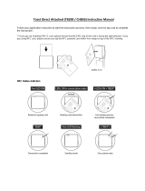
Box Contents ........................................................................................................................................... 5
Product Description ................................................................................................................................. 6
Terminal Ports ......................................................................................................................................... 8
Back Cover Plate ...................................................................................................................................... 9
Remove Back Cover Plate .................................................................................................................... 9
Replace Back Cover Plate ..................................................................................................................... 9
Terminal Location .................................................................................................................................... 9
Paper..................................................................................................................................................... 10
Load Paper ........................................................................................................................................ 10
Advance Paper................................................................................................................................... 12
Tear Paper ......................................................................................................................................... 12
AC Power Connection ............................................................................................................................ 13
Terminal Communications ..................................................................................................................... 14
Wi-Fi Service ...................................................................................................................................... 14
LAN Ports .......................................................................................................................................... 15
Dual-SIM Feature ............................................................................................................................... 16
Install SIM or Micro SD Card (If Equipped) ......................................................................................... 17
Hybrid Card Reader ............................................................................................................................... 18
Magnetic Stripe Reader ..................................................................................................................... 18
EMV Card Reader .............................................................................................................................. 18
NFC/Contactless Card Reader ............................................................................................................ 18
Replacing Battery (If Required) .............................................................................................................. 19
Cable Lock (If Required) ......................................................................................................................... 20
Cleaning the Device ............................................................................................................................... 21
Basic Operation Instructions .................................................................................................................. 22
Power ON .......................................................................................................................................... 22
Power OFF ......................................................................................................................................... 22
PAX Customer Support .......................................................................................................................... 23

PAX E500 INSTALLATION MANUAL
3
20181002-v0.5
Revision History
Date
Version
Description of Change
Oct. 4, 2017
0.1
Initial draft of document.
Oct. 4, 2017
0.2
Update instructions for inserting an EMV card into the EMV
Card Reader in the Hybrid Card Reader section.
Add additional detail to uses of LAN A, LAN B, Cash Drawer,
HDMI, and Audio Jack ports in the Terminal Ports section.
Nov. 9, 2017
0.3
Add Packaging section that includes information about
labels with part numbers and serial numbers for E500 and
Q20 on outside of terminal box. Includes information about
the availability of another box that may be purchased for
returning the unit to PAX for service.
Nov. 20, 2017
0.4
Change the amount of time to hold the power button down
to turn the unit on or off from two seconds to three
seconds.
Change the SAM Cover to SIM Cover.
Add that T-Mobile and AT&T SIM cards do not need to be
configured.
Oct. 2, 2018
0.5
Add that the K-Slot is not metal reinforced.
Update the address for PAX Customer Support.
1.0
Initial release.

PAX E500 INSTALLATION MANUAL
4
20181002-v0.5
Introduction
The PAX™ E500 is a next generation electronic cash register solution with an integrated Q20 customer-
facing payment module. Its all-in-one housing unit combines a tablet, printer, PED, and ports. The
modular design provides a seamless user experience using the PayDroid payment application which is
based on Android.
The PAX E500 Installation Manual includes information about:
• Terminal packaging
• What is included in the box
• Product description
• Terminal ports
• Removing and replacing the back cover plate
• Where to place the device
• Loading paper
• Connecting power
• Terminal communications
• Hybrid card reader
• Replacing the battery
• Installing a cable lock
• Cleaning the device, and
• Turning the E500 on and off

PAX E500 INSTALLATION MANUAL
5
20181002-v0.5
Packaging
Before you remove the terminal from the box, please note there are labels with the part number and
serial number of the E500 and the Q20 on the outside of the box.
Note: Part number and serial number labels for the E500 and the Q20 are also affixed to the underside
of the unit.
You can retain the original box in case the unit needs to be shipped to PAX for service or, alternatively,
you can purchase a box specially designed for return shipping to PAX, if required.
Box Contents
• 1 - PAX™ E500 with Integrated Q20 Customer-Facing Payment Module
• 1 - AC Power Adapter (PN 200310110000135)
• 1 - AC Power Cord (PN 200311020000023)
• 1 - Thermal Paper Roll
Note: Product images shown may be different than actual product received.


PAX E500 INSTALLATION MANUAL
8
20181002-v0.5
Terminal Ports
At the back of the E500, ports enable the terminal to add peripherals such as PIN pads, check readers,
contactless readers, other external devices, to enable local terminal downloads and communications,
and to provide power. The ports are labeled and color-coded.
The following connectors are available on the back of the E500:
• Cash Drawer (RJ11, 24V) – Used to connect to the cash drawer
• RS232 (RJ45) – Used to connect an external POS device or check reader
• LAN A – Used for bi-directional Ethernet connections using DSL or Cable
• LAN B – Used for bi-directional Ethernet connections using DSL or Cable
• USB-Host – Type A
• HDMI (1.4 Type A) – Used to connect to HD TV or display. Supports 720P or above.
• USB-OTG (Micro-B) - Used for local terminal downloads or external peripherals
• Audio Jack – Supports the microphone
• AC Power - Used to connect AC power supply to the terminal
There is an additional USB-Host 2.0 port on the right side of the terminal, as shown below:

PAX E500 INSTALLATION MANUAL
9
20181002-v0.5
Back Cover Plate
Remove Back Cover Plate
1. Grasp the plastic tabs on both sides of the lower edge of the cover plate with your thumbs.
2. Pull up until the cover plate releases.
Note: If you cannot remove the cover plate with your hands, use a flat head screwdriver to
release the lower edge of the cover plate.
3. Slide the cover plate, releasing the three upper plastic tabs at the top of the cover, and remove
the cover plate.
Replace Back Cover Plate
1. Ensure the cables are properly dressed through the cable retention openings on the back of the
E500.
2. Align the three plastic tabs at the top of the cover plate into the slots on the terminal.
3. Align the sides of the cover plate and push until the cover plate snaps into place.
Terminal Location
Locate the terminal on a counter top, desktop or table top. Keep the terminal away from direct sunlight,
excessive dust, moisture, and heat. Avoid locating the terminal near electrical devices that might
introduce interference such as microwave ovens and blow dryers.

PAX E500 INSTALLATION MANUAL
10
20181002-v0.5
Paper
Load Paper
1. To open the paper holder, press the large button to the right of the paper holder door, as shown
below:
At the back of the open paper holder, there is a diagram that shows the proper way to insert the
paper.
Note: The paper width and diameter are 80mm.

PAX E500 INSTALLATION MANUAL
11
20181002-v0.5
2. Place the paper roll inside the paper holder with the paper feeding from the top of the paper
roll.
3. Pull out approximately 5 inches of paper and close the lid.
4. Firmly press the door closed until it snaps in place. The terminal automatically cuts the excess
paper.
Note: When the paper holder is open, the Paper-Out button lights orange and the Error button
flashes red.

PAX E500 INSTALLATION MANUAL
12
20181002-v0.5
Advance Paper
1. Press the white and gray advance paper button located to the left of the paper holder, as shown
below:
The paper will advance approximately 1/3” with each push of the button.
Note: The terminal must be connected to power to use the advance paper button. The button
will not work when the E500 is battery powered.
Tear Paper
When connected to power, the E500 automatically cuts excess paper when the paper holder is closed.
However, if the E500 is running on battery power, you can tear the paper by hand.
1. Tilt the paper toward the bottom of the terminal at about a 45-degree angle.
2. Pull the paper from the left or right across the tear off bar inside the terminal.

PAX E500 INSTALLATION MANUAL
13
20181002-v0.5
AC Power Connection
The terminal uses a two-piece AC power supply and cord. It is highly recommended to use surge
protection and a UPS backup power supply with battery backup.
To apply power:
1. Connect the two-piece power supply and power cable together.
2. Plug the round power connector with the semi-circle plug into the terminal power port.
3. Route the power cord through the cable retention slot located at the bottom of the terminal.
4. After all terminal cables are connected, plug the terminal AC power cable to the power source.
WARNING:
DO NOT connect the other end to the AC power source until all the other cables are
connected first. Plugging in the AC power cord to the power source before the other cables
are installed may result in damage to the terminal or connected devices.
WARNING:
Do not disconnect the power supply while applications are being downloaded to the terminal.
The applications could be downloaded improperly or the Flash memory could be damaged.

PAX E500 INSTALLATION MANUAL
14
20181002-v0.5
Terminal Communications
The E500 supports the following types of communication:
• Ethernet LAN
• Serial Port RS232
• USB
• GSM/GPRS
• WDCMA
• TD-SCDMA
• 4G FDD-LTE & TD-LTE
• Wi-Fi 802.11 b/g/n
• Bluetooth BLE 4.0
• PSTN Dial Modem (optional with EM100 external module)
Wi-Fi Service
The terminal Wi-Fi capability allows the terminal to connect to a wireless network allowing the flexibility
to locate the terminal almost anywhere within the wireless network coverage area. Using wireless
communications allows the terminal to send and receive transaction information quickly resulting in fast
transaction times.
To setup wireless communications, configure the terminal Wi-Fi parameters to the Wi-Fi network
settings.
Note: The SSID wireless access point name and wireless security password is case sensitive and must
exactly match the Wi-Fi network settings. Also, be sure to set Wi-Fi as the Main or Back up
communication method according to your installation needs.

PAX E500 INSTALLATION MANUAL
15
20181002-v0.5
LAN Ports
Using Ethernet communications allows the terminal to send and receive transaction information quickly
resulting in fast transaction times. The LAN port is used for Ethernet connections using DSL or Cable.
To connect to an internal LAN port:
1. Connect an Ethernet cable with an RJ45 connector into the LAN A or LAN B port on the back of
the E500.
2. Route the Ethernet cable through the cable retention slot on the bottom of the terminal.
Note: Set Wi-Fi as the Main or Back up communication method according to your installation
needs.

PAX E500 INSTALLATION MANUAL
16
20181002-v0.5
Dual-SIM Feature
The dual-SIM E500 holds two SIM cards, providing a failover using two separate wireless carriers. If your
E500 is equipped with SIM cards from different wireless carriers and your coverage under the first
wireless carrier were to fail, the E500 would automatically switch over to your second carrier,
preventing a loss of coverage.
You can set up a priority list, similar to the example below, where the E500 will continue to attempt to
use the higher priority communication type until it fails. At that point, the E500 will failover to the next
available one on your priority list.
1. Ethernet LAN
2. Wi-Fi
3. Wireless SIM1
4. Wireless SIM 2
5. PSTN Dial Modem (using optional EM100)

PAX E500 INSTALLATION MANUAL
17
20181002-v0.5
Install SIM or Micro SD Card (If Equipped)
To install a SIM card or Micro SD card:
1. Using a flat head screwdriver, loosen the captive screw from the SIM cover on the back of the
E500.
2. Remove the SIM cover.
3. Insert the card.
4. Align the card, as shown in the drawing and insert firmly into slot.
5. Align the two plastic tabs on the cover plate into the slots on the terminal.
6. Push the cover plate into place.
7. Tighten the captive screw on the cover plate.
Note: T-Mobile and AT&T SIM cards do not need to be configured.

PAX E500 INSTALLATION MANUAL
18
20181002-v0.5
Hybrid Card Reader
The Q20 on the consumer-facing side of the E500 includes a reader can be used as an EMV Card Reader
and a NFC/Contactless Card Reader.
Magnetic Stripe Reader
To use the Magnetic Stripe Reader, insert the Magnetic Stripe card into the card reader slot located on
the top of the Q20. The terminal reads the information from the magnetic stripe card when the
magnetic stripe is inserted into the card slot.
EMV Card Reader
To use the EMV Card Reader, insert the EMV Card with the front of the card facing you and the chip
down into the card slot located on the top of the Q20. Leave the card inserted until the terminal
provides a message to remove the card.
NFC/Contactless Card Reader
To use the NFC/Contactless Card Reader, tap the NFC/Contactless card to the Q20 screen when
prompted. The terminal uses an antenna device that detects and retrieves information from the card.

PAX E500 INSTALLATION MANUAL
19
20181002-v0.5
Replacing Battery (If Required)
To replace the battery:
1. Carefully position the E500 so you have access to the bottom of the unit.
2. Using a slot head screwdriver, loosen the captive screw.
3. Remove the battery cover.
4. Gently roll the battery out of its storage compartment.
5. Carefully separate the white connector from its socket and pull the connector straight up from
the socket to remove.
Important: Do not pull the battery by its wires when you are removing it. The connector or
battery may be damaged.
6. Insert the replacement battery into the battery compartment.

PAX E500 INSTALLATION MANUAL
20
20181002-v0.5
Note: The white plastic arrow slots on the battery connector, as shown below, must face
toward you when you insert it into the battery port.
7. Firmly seat the white battery connector into its socket.
8. Insert the two tabs on the battery cover plate and slide the cover plate into place.
9. Tighten the captive screw on the cover plate.
Cable Lock (If Required)
To install a cable lock:
1. Insert a customer-provided cable lock into the K-Slot® on the terminal.
2. Loop the cable around a permanent object and secure in place.
Note: The K-Slot is not metal reinforced.
/