DeWalt D55570 User manual

Category
Air compressors
Type
User manual
DEWALT Industrial Tool Co., 701 East Joppa Road, Baltimore, MD 21286 (FEB03) Form No. 5134371-00 Multi Elect Air Compressors
Copyright © 2001, 2003
DEWA LT The following are trademarks for one or more DEWA LT power tools: the yellow and black color scheme; the “D shaped air intake grill;
the array of pyramids on the handgrip; the kit box configuration; and the array of lozenge-shaped humps on the surface of the tool.
5134371,DW55170,ElecComp 2/10/03 2:38 PM Page 2
INSTRUCTIVO DE OPERACIÓN, CENTROS DE SERVICIO Y PÓLIZA
DE GARANTÍA. ADVERTENCIA: LÉASE ESTE INSTRUCTIVO ANTES
DE USAR EL PRODUCTO.
INSTRUCTION MANUAL
GUIDE D'UTILISATION
MANUAL DE INSTRUCCIONES
D55170, D55170T, D55180, D55180T, D55390, D55395, D55570, D55570T, D55575,
D55580, D55580T, D55585
Contractor’s Electric Wheeled Portable Air Compressor
Compresseur d’air électrique portatif sur roues de classe entrepreneur
Compresor de aire eléctrico portátil con ruedas para contratistas
Questions? See us on the World Wide Web at www.dewalt.com
5134371,DW55170,ElecComp 2/10/03 2:38 PM Page 3
Motor Specifications
1.5 Hp
115 Volt, 15 amps, 60Hz
230 Volt, 8 amps, 60 Hz
Four pole, induction type,1725 RPM
2 Hp
115 Volt, 20 amps, 60 Hz
230 Volt, 10 amps, 60 Hz
Four pole, induction type,1725 RPM
3 Hp
230 Volt, 10 amps, 60 Hz
Four pole, induction type,1725 RPM
G Pump Specifications
V - twin 4 cylinder
Single Stage
Oil Lubricated
Cast Iron crankcase, cylinder, and head
Bore: 2-1/2" (63.5 mm)
Stroke: 2-3/8" (60.33 mm)
Weight: 69 lbs. (31.29 kg.)
Oil Capacity: 30 oz.
K Pump Specifications
Inline, vertical twin cylinder
Single Stage
Oil Lubricated
Cast Iron crankcase, cylinder, and head
Bore: 2-1/2" (63.5 mm)
Stroke: 2" (50.8 mm)
Weight: 47 lbs. (21.31 kg.)
Oil Capacity: 14 oz.
5134371,DW55170,ElecComp 2/10/03 2:38 PM Page 4
CONSTANT RUN
8 GALLON PORTABLE
D55170, D55170T* - 1.5 HP Motor
D55180, D55180T* - 2 HP Motor
DUAL CONTROL
8 GALLON PORTABLE
D55390 - 3 HP, 230 VOLTS
DUAL CONTROL
17 GALLON PORTABLE
D55395 - 3 HP, 230 VOLTS
* “T” denotes 2-wheel version
5134371,DW55170,ElecComp 2/10/03 2:38 PM Page 5
SPECIFICATIONS
MODEL WEIGHT HEIGHT WIDTH LENGTH Typical values @ 100 psi
SCFM Current
D55170 168 lbs. (76.20 kg.) 33.0 in. (838.2 mm) 22.5 in. (571.5 mm) 45.0 in. (1143.0 mm) 6.5 15 amps
D55180 172 lbs. (78.02 kg.) 23.5 in. (596.9 mm) 18.25 in. (463.55 mm) 43.0 in. (1092.2 mm) 8.4 20 amps
D55390 231 lbs. (108.78 kg.) 26.25 in. (666.75 mm) 18.25 in. (463.55 mm) 43.0 in. (1092.2 mm) 13.3 10 amps
D55395 254 lbs. (115.21 kg.) 32.0 in. (812.8 mm) 20.25 in. (514.35 mm) 43.0 in. (1092.2 mm) 13.3 10 amps
D55570 168 lbs. (76.20 kg. 23.5 in. (596.9 mm) 18.25 in. (463.55 mm) 43.0 in. (1092.2 mm) 6.5 8 / 15 amps
D55575 194 lbs. (87.99 kg.) 29.75 in. (755.65 mm) 20.25 in. (514.35 mm) 43.0 in. (1092.2 mm) 6.5 8 / 15 amps
D55580 175 lbs. (78.38 kg.) 23.5 in. (596.9 mm) 18.25 in. (463.55 mm) 43.0 in. (1092.2 mm) 8.4 10 / 20 amps
D55585 201 lbs. (91.17 kg.) 29.75 in. (755.65 mm) 20.25 in. (514.35 mm) 43.0 in. (1092.2 mm) 8.4 10 / 20 amps
DUAL VOLTAGE / DUAL CONTROL
8 GALLON PORTABLE
D55570, D55570T* - 1.5 HP Motor
D55580, D55580T* - 2 HP Motor
DUAL VOLTAGE / DUAL CONTROL
17 GALLON PORTABLE
D55575 - 1.5 HP Motor
D55585 - 2 HP Motor
* “T” denotes 2-wheel version
5134371,DW55170,ElecComp 2/10/03 2:38 PM Page 6
1
AIR TANK
The tank on your Air Compressor is designed and may be UM coded
(for units with tanks greater than 6 inch diameter) according to ASME
Section VIII, Div. 1 rules. All pressure vessels should be inspected
once every two years. To find your state pressure vessels inspector,
look under the Division of Labor and Industries in the government
section of a phone book or call 1-800-4DEWA LT for assistance.
The following conditions could lead to a weakening of the tank, and
result in a violent tank explosion:
1. Failure to properly drain condensed water from the tank can
causing rust and thinning of the steel tank. Drain tank daily or
after each use. If tank develops a leak, replace it immediately with
a new tank or new compressor outfit.
2. Modifications or attempted repairs to the compressor tank.
Never drill into, weld, or make any modifications to the tank or its
a t t a c h m e n t s .
3. Do not modify the safety valve, or any other components that
control tank pressure. The tank is designed
to withstand specific operating pressures.
Never make adjustments or parts substitutions
to alter the factory set operating pressures.
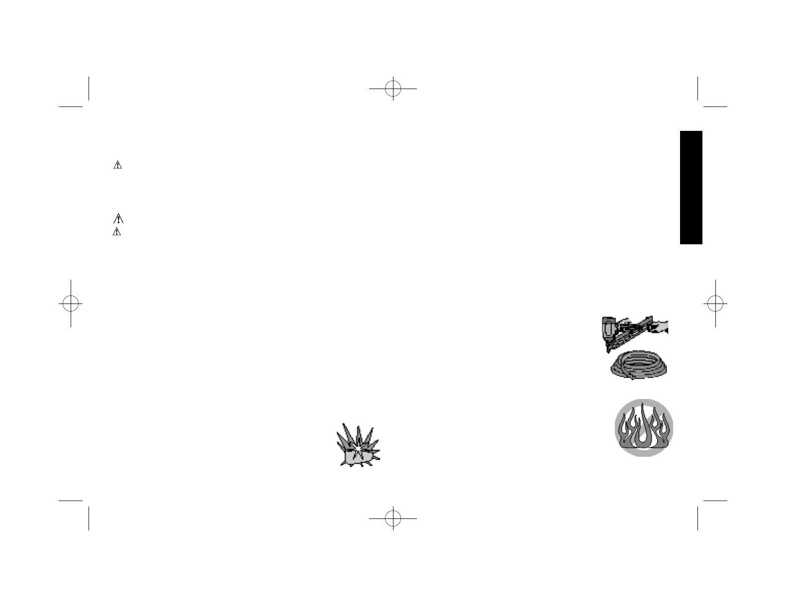
ATTACHMENTS & ACCESSORIES
Exceeding the pressure rating of air tools, spray
guns, air operated accessories, tires and other
inflatables can cause them to explode or fly apart,
and could result in serious injury. Follow the equipment manufacturers
recommendation and never exceed the maximum
allowable pressure rating of attachments. Never use
the compressor to inflate small low-pressure objects
such as children’s toys, footballs, basketballs, etc.
RISK OF EXPLOSION OR FIRE
Always operate the compressor in a well-ventilated
area free of combustible materials, gasoline or solvent
vapors. If sparks from compressor come into contact with flammable
IF YOU HAVE ANY QUESTIONS OR COMMENTS ABOUT THIS
OR ANY DEWA LT TOOL, CALL US TOLL FREE AT 1-800-4-
D E WA LT (1-800-433-9258).
WARNING! Read and understand all instructions before
operating this compressor. Failure to follow all instructions listed
below may result in electric shock, fire and/or serious personal injury.
SAVE THESE INSTRUCTIONS
Safety Instructions
WARNING: Some dust created by this product contains chemicals
known to State of California to cause cancer, birth defects or other
reproductive harm. Some examples of these chemicals are:
compounds in fertilizers
compounds in insecticides, herbicides and pesticides
arsenic and chromium from chemically treated lumber
To reduce your exposure to these chemicals, wear approved safety
equipment such as dust masks that are specially designed to filter out
microscopic particles.
WARNING: Use of this product will expose you to chemicals known
to the State of California to cause cancer, birth defects and other
reproductive harm. Avoid inhaling vapors and dust, and wash
hands after using.
WARNING: This product contains chemicals, including lead, known
to the State of California to cause cancer, and birth defects or other
reproductive harm. Wash hands after handling.
Improper operation or maintenance of this product could result in
serious injury and property damage.
The user of the air compressor must understand these
instructions. Each person operating the air compressor
must be of sound mind and body and must not be under
the influence of any substance, which might impair vision,
d e x t e r i t y, or judgement.
5134371,DW55170,ElecComp 2/10/03 2:38 PM Page 1
2
vapors, they may ignite, causing fire or explosion. If spraying
flammable materials, locate compressor at least 20 feet up wind from
spray area. An additional length of hose may be required.
Store flammable materials in a secure location away from compressor.
Restricting any of the compressor ventilation openings will cause
serious overheating and could cause fire. Never place objects against
or on top of compressor. Operate compressor in an open area at
least 3 feet away from any wall or obstruction that would restrict the
flow of fresh air to the ventilation openings.
RISK FROM FLYING OBJECTS
The compressed air stream can cause soft tissue damage to exposed
skin and can propel dirt, chips, loose particles and small objects at high
speed, resulting in serious injury. Always wear ANSI Z28.1 approved
safety glasses with side shields when using the compressor. Never
direct air stream at people or animals. Use only OSHA approved air
blow guns.
RISK TO BREATHING
The compressed air from your compressor is not safe
for breathing! The air stream may contain carbon
monoxide, toxic vapors or solid particles. Never inhale
air from the compressor either directly or from a
breathing device connected to the compressor.
Sprayed materials such as paint, paint solvents, paint
r e m o v e r, insecticides, weed killers, etc. contain harmful vapors and
p o i s o n s . NOTE: Operate air compressor only in a well ventilated area.
Read and follow the safety instructions provided on the label or safety
data sheets for the material you are spraying. Use a NIOSH/MSHA
approved respirator designed for use with the specific
a p p l i c a t i o n .
RISK FROM MOVING PARTS
Always turn off the compressor, bleed pressure from
the air hose and tank, and disconnect from power
source before performing maintenance or attaching
tools and accessories.
Keep your hair, clothing, and gloves away from moving parts. Loose
clothes, jewelry, or long hair can be caught in moving parts. Air vents
may cover moving parts and should be avoided as well. Do not
remove the protective covers from this product. Never operate
compressor with guards or protective covers that are damaged or
removed. Never stand on the compressor.
HOT SURFACES
Touching exposed metal such as the compressor head or aftercooler
COMPRESSOR
CYLINDER & HEAD
AFTERCOOLER
PUMP
CRANKCASE
ELECTRIC
MOTOR
HOT SURFACES
COMPRESSOR
CYLINDER & HEAD
AFTERCOOLER
PUMP
CRANKCASE
ELECTRIC
MOTOR
HOT SURFACES
5134371,DW55170,ElecComp 2/10/03 2:38 PM Page 2
can result in serious burns. Never touch any exposed metal parts on
compressor during or immediately after operation. Compressor will
remain hot for several minutes after operation. Do not move the
compressor while it is running. Hot motor parts could cause burns
contributing to the dropping of the compressor,
damaging the compressor and/or injuring the operator.
RISK OF ELECTRICAL SHOCK
Your air compressor is powered by electricity, if it is not
used properly it could cause electric shock. Never
operate the compressor out-doors when it is raining or
in wet conditions.
Never operate compressor with guards or protective covers that are
damaged or removed. Repairs by anyone other than qualified
personnel can result in serous injury or death by electrocution. Any
electrical wiring or repairs required on this product should be performed
by authorized service personnel in accordance with national and local
electrical codes.
REPAIR OR REPLACE DAMAGED OR WORN CORDS IMMEDIATELY.
THE USE OF A GFCI OUTLET IS RECOMMENDED AND MAY
BE REQUIRED IN CERTAIN AREAS
RISK FROM NOISE
CAUTION: Wear appropriate personal hearing
protection during use. Under some conditions and
duration of use, noise from this product may contribute to
3
hearing loss.
DEWA LT does not recommend the use of extension cords as this
can create power loss and overheating of the motor. Use of an
additional air hose is recommended rather than the extension cord. If
use of an extension cord is unavoidable, it should be plugged into a
GFCI found in circuit boxes or protected receptacles. When using an
extension cord, observe the following.
GROUNDING INSTRUCTIONS
In the event of a malfunction or breakdown, grounding provides a path
of least resistance for electric current to reduce the risk of electric
shock. This tool is equipped with an electric cord having an equipment-
grounding conductor and grounding plug. The plug must be plugged
into a matching outlet that is properly installed and grounded in
accordance with all local codes and ordinances. Make sure that the
electrical circuit to which the compressor is connected provides proper
electrical grounding, correct voltage and adequate fuse protection.
Do not modify plug provided: if it will not fit the outlet, have the proper
outlet installed by a qualified electrician.
Improper connection of the equipment-grounding conductor can result
in a risk of electric shock. The conductor with insulation having an outer
surface that is green with or without yellow stripes is the equipment-
grounding conductor. If repair or replacement of the electric cord or
plug is necessary do not connect the equipment-grounding conductor
to a live terminal.
Check with a qualified electrician or service personnel if the grounding
instructions are not completely understood or if in doubt as to whether
the tool is properly grounded.
Use only 3-wire extension cords that have 3-prong grounding plugs
and 3-pole receptacles.
Grounded tools intended for use on a supply circuit having a nominal
rating less than 150 volts: This tool is intended for use on a circuit that
has an outlet that looks like the one illustrated in Figure A.The tool has
a grounding plug that looks like the plug illustrated in Figure A.
temporary adapter, which looks like the adapter illustrated in Figures
Extension Cord Chart
1.5 Hp Motor
Rating Length of Cord in Feet
25’ 50’ 100’
16 amp, 115V 14 Ga. 12 Ga. 10 Ga.
8 amp, 230V 16 Ga. 16 Ga. 14 Ga.
2 Hp Motor
Rating Length of Cord in Feet
25’ 50’ 100’
20 amp, 115V 14 Ga. 12 Ga. 8 Ga.
9 amp, 230V 16 Ga. 16 Ga. 14 Ga.
5134371,DW55170,ElecComp 2/10/03 2:38 PM Page 3
4
B and C, may be used to connect this plug to a 2-pole receptacle as
shown in Figure B if a properly grounded outlet is not available. The
temporary adapter should be used only until a properly grounded outlet
can be installed by a qualified electrician, The green-colored rigid ear,
lug, and the like, extending from the adapter must be connected to a
permanent ground such as a properly grounded outlet box.
The adapter (C) is not for use in Canada
A LWAYS STORE COMPRESSOR IN A HORIZONTAL POSITION,
ON ALL FOUR RUBBER MOUNTS.
Introduction
Congratulations on the purchase of your new DEWA LT Air Com-
pressor! You can be assured that this tool has been constructed with
the highest level of precision and accuracy. Each component has been
rigorously tested by technicians to ensure the quality, endurance and
performance of this air compressor.
By reading and following the safety, operation, maintenance and
troubleshooting steps described in this manual, you will receive years
of trouble-free operation.
The manufacturer reserves the right to make changes in price, color,
materials, equipment specifications or models at any time without
n o t i c e .
Inspection of Compressor
Inspect for signs of obvious or concealed freight damage. Report any
damage to the delivering freight carrier immediately. Be sure that all
damaged parts are replaced and any mechanical problems are
corrected prior to the operation of the air compressor. The air
compressor serial number is located on the deck of the air compressor
and pump bearing cap. Please write the serial number in the space
provided in the service section for future reference.
Features
DUAL CONTROL
This feature allows the compressor to operate in either the constant run
or the stop/start mode of operation. The pilot valve is used to control
the compressor when operating in the constant run mode. The
pressure switch is used to control the compressor when operating in
the stop/start mode. The mode of operation is determined by the
amount of time the compressor will be required to supply air. If the
demand for air is infrequent, then the unit should be set up for stop/start
operation to minimize unnecessary run time and to save energy. If
there is a frequent or extended demand for air, and/or the unit is
located in a remote area where access to the compressor is diff i c u l t ,
the unit should be set up for constant run to minimize the number of
times the motor must start in an hour to ensure good motor life.
DUAL VOLTAGE
This feature allows the compressor to operate in either 120 or 240 volt
environments. The advantage of running in the 240 volt range is a
lower current draw. Lower current draw may be necessary in areas
with a poor power source. Lower current also reduces operating costs.
If running in the 240 volt mode, the plug end must be replaced with
the appropriate plug.
PILOT VALVE
Pilot valves are used to maintain a constant
pressure range while running continuously. The
pilot valve may be used to operate a discharge line
unloader or an unloading device in the compressor
head. The DEWA LT compressor unloads through
the compressor head. Unloading occurs when the
receivers (tanks) reach a preset cut-out pressure.
A B C
GROUNDING PIN
GROUNDED
OUTLET
BOX
GROUNDING
MEANS
ADAPTER
5134371,DW55170,ElecComp 2/10/03 2:38 PM Page 4
5
The pilot valve opens, actuating the unloading device that allows the
compressor to run in an unloaded
mode. When the tank pressure drops
to the preset cut-in pressure, the pilot
valve closes allowing the unloading
device to close and the compressor
once again pumps into the tanks.
Manual Lock (for D55170 and D55180):
The manual lock allows you to manually unload the compressor with
air pressure in the tank. To operate the unloading device in the head,
rotate the flip lever to an in-line position (dashed lines). Be sure to
return lever to the loaded position after starting the engine or the pump
will not operate at preset pressures.
PRESSURE SWITCH
This switch (A) is used to start or stop the air
c o m p r e s s o r. Moving the switch to the "ON"
position will provide automatic power to the
pressure switch which will allow the motor to start
when the air tank pressure is below the factory
set "cut-in" pressure. When in the "ON (AUTO ) "
position, the pressure switch stops the compressor from charging air
when the air tank pressure reaches the factory set "cut-out" pressure.
For ease of starting this switch also has a pressure release valve
located on the side of the switch designed to automatically release
compressed air from the air compressor pump head and its discharge
line when the air compressor reaches "cut-out" pressure or is shut off .
Moving the switch to the "OFF" position will open the pressure switch
contacts and stop the air compressor.
SAFETY RELIEF VALVE
This valve (B) is designed to prevent system failures
by relieving pressure from the system when the
compressed air reaches a predetermined level. The
valve is preset by the manufacturer and must not be
removed or modified in any way.
AIR INTAKE FILTER
This filter (C) is designed to clean air entering the pump.
To ensure the pump continually receives a clean, cool,
and dry air supply this filter must always be clean and
filter intake must be free from obstructions.
AIR TANK DRAIN VALVES
The drain valves (D) are used to remove
moisture from the air tank after the air
compressor is shutoff .
TANK PRESSURE GAUGE
The tank pressure gauge (E) indicates air
pressure in the air tank.
REGULATED PRESSURE GAUGE
The regulated pressure gauge (F) indicates the
air pressure available at the outlet side of the
r e g u l a t o r. This pressure is controlled by the
regulator and is always less or equal to the air
tank pressure.
PRESSURE REGULATOR
The regulator knob (G) controls the air pressure coming from the air
t a n k .
Common Procedures
230 VOLT OPERATION
Ensure that cord requirements have been met.
Ensure that motor requirements have been met.
Ensure that dual voltage switch is in the proper position if
so equipped.
CORD REQUIREMENTS
If it is desired to operate your compressor at 230 volts it is also
necessary to replace the 115 volt plug, supplied with the motor, with a
D
C
E
F
G
B
A
5134371,DW55170,ElecComp 2/10/03 2:38 PM Page 5
6
UL/CSA listed plug suitable for 230 volts and the
rated current of the compressor as shown. A 230
volt plug as shown in the diagram can be
purchased at your local hardware or electrical
supply store. Follow the cord plug manufacturer
installation procedures, contact your local DEWA LT
Service Center, qualified electrician or call 1 - 8 0 0 -
4 - D EWA LT for proper procedures to install the plug.
The compressor must comply with all local and national electrical
codes after the 230 volt plug is installed.
The compressor with the 230 volt plug should only be connected to
an outlet having the same configuration as the plug illustrated.
MOTOR REQUIREMENTS
UNITS WITHOUT A DUAL VOLTAGE SWITCH
WA R N I N G : Make sure motor is disconnected from the power
source before rewiring motor leads.
The motor supplied with your compressor is a dual voltage, 115 / 230
volt motor. If it is desired to operate your compressor at 230 volts,
single phase, it is necessary to reconnect the motor leads in the motor
junction box by following the instructions given on the motor
nameplate. If unsure on how to reconnect the motor leads contact
your local DEWA LT Service Center or qualified electrician for proper
procedures to install the plug.
WA R N I N G : Make sure that the 230 volt cord plug end is properly
connected before operating in 230 volt mode.
UNITS WITH A DUAL VOLTAGE SWITCH
WA R N I N G : Make sure that the 230 volt cord plug end is properly
connected before operating in 230 volt mode.
The motor supplied with your compressor is a dual voltage, 11 5 / 2 3 0
volt motor. If it is desired to operate your compressor at 230 volts,
single phase, simply move the 115/230 volt switch to the 230 volt
p o s i t i o n .
DUAL CONTROL
(D55390, D55395, D55570, D55575, D55580, D55585)
N O T E : Unit must remain running while performing the following
a d j u s t m e n t s
WARNING : A f t e r c o o l e r, pump head, and surrounding parts are
very hot; do not touch. (see the Hot Surfaces identified on page 2)
WARNING - Moving Parts: Keep your hair, clothing and gloves
away from moving parts. Loose clothing, jewelry, or long hair can be
caught in moving parts. Air vents may cover moving parts
and should be avoided as well.
Stop Start Mode
1. Turn compressor on. If the tank has been fully charged,
bleed air from the drain valves until pump starts.
2. Turn knob on top of pilot valve (H) clockwise until fully
c l o s e d .
WARNING : Over tightening of this knob can cause
damage to the pilot valve.
3 . Allow compressor to reach cut out pressure. If
compressor does not stop, drain the tank(s) until compressor
begins to charge the tank(s) and readjust pilot valve knob.
Constant Run Mode
1 . Turn compressor on. If the tank has been fully charged, bleed air
from the drain valves until pump starts.
2 . Turn knob on top of pilot valve (H) fully counter-clockwise until fully
o p e n .
WARNING : Over loosening of this knob can cause damage to the
pilot valve.
3 . Verify that the unit is in a constant run mode. If compressor shuts
o f f, adjust pilot valve to a lower cut out pressure until unit continues
H
5134371,DW55170,ElecComp 2/10/03 2:38 PM Page 6
7
to run.
N O T E : For proper operation the pilot valve cut out pressure must be
below the pressure switch cut out pressure.
PILOT VALVE CUT-OUT PRESSURE ADJUSTMENT
N O T E : Unit can remain running while performing this adjustment
WARNING : A f t e r c o o l e r, pump head, and surrounding parts are
very hot; do not touch. (see the Hot Surfaces identified on page 2)
WARNING - Moving Parts: Keep your hair, clothing and gloves
away from moving parts. Loose clothing, jewelry, or long hair can be
caught in moving parts. Air vents may
cover moving parts and should be avoided
as well.
WARNING : The pilot valve is brass
which is a soft metal. Do not overtighten
screw as threads can strip out.
1 . Hold “K” firmly and loosen nut “J”.
WARNING : Do not loosen screw “Imore than 1 revolution as
screw is subjected to tank pressure and can burst out which can harm
the user or surrounding personnel.
2 . Turn screw “I” clockwise to increase cut-out pressure limit or
counter clockwise to decrease cut-out pressure. (example: if the
cut-out pressure on the tank gauge reads 120 psi. and desired cut
out is 130 psi, turn screw “I” clockwise)
3 . Drain air from tanks through drain valves until pump begins to
charge tanks.
4 . Close drain valves.
5 . Monitor cut-out pressure to verify the new setting
6 . Once setting is complete hold screw “H” firmly
7 . Hold “K” firmly and tighten nut “J”
PILOT VALVE PRESSURE DIFFERENTIAL ADJUSTMENT
N O T E : Unit can remain running while performing this adjustment
WARNING : A f t e r c o o l e r, pump head, and surrounding parts are
very hot; do not touch. (see the Hot Surfaces identified on page 2)
WARNING - Moving Parts: Keep your hair, clothing and gloves
away from moving parts. Loose clothing, jewelry, or long hair can be
caught in moving parts. Air vents may cover moving parts and should
be avoided as well.
1 . Hold “K” firmly and loosen nut “L”
WARNING :Do not loosen barrel “I” more than 1 revolution as barrel
is subjected to tank pressure and can burst out which can harm the
user or surrounding personnel.
2 . Turn barrel “K clockwise to increase differential or counter
clockwise to decrease differential. (for example: if pressure
d i fferential is 100 - 130 psi and 100 - 120 psi is desired, turn “K”
counter clockwise)
NOTE : Too narrow of a differential can cause chatter of the pilot valve.
Increase differential to eliminate chatter.
3 . Hold barrel “K
4 . Hold “J” firmly and tighten nut “L
CHECKING COMPRESSOR PUMP OIL LEVEL
WA R N I N G : A f t e r c o o l e r, pump head, and surrounding parts are very
hot, do not touch. (see the Hot Surfaces identified
on page 2)
1 . Ensure Unit is off .
2. Locate unit onto a flat horizontal surface.
3 . Remove knurled filler knob (M) from crankcase.
4 . Insert a clean screwdriver into the crankcase
and remove it.
5 . Look for visual signs of contaminants (water, dirt, etc.) Change
pump oil if contaminants are present.
6 . Oil should not exceed top raised line on side of crankcase (oil will be
even with bottom of threads in crankcase fill port). If necessary fill
I
J
K
M
L
5134371,DW55170,ElecComp 2/10/03 2:38 PM Page 7
8
with DEWA LT synthetic oil.
CHECKING SAFETY RELIEF VALVE OPERATION
WA R N I N G : A f t e r c o o l e r, pump head, and surrounding parts are very
hot, do not touch. (see the Hot Surfaces identified on page 2)
1 . Ensure unit is off.
2 . Ensure tanks are empty by looking at tank pressure gage. Drain
tanks if necessary.
3 . Grasp wire ring on safety valve.
4 . Pull and release ring a few times to ensure plunger moves in and
o u t .
CHECKING AIR FILTER ELEMENT
WA R N I N G : A f t e r c o o l e r, pump head, and surrounding parts are very
hot, do not touch. (see the Hot Surfaces identified on page 2)
1 . Ensure unit is off .
2 . Allow unit to cool.
3 . Unscrew filter top from filter base by turning counter clockwise
about 5 degrees.
4 . Separate filter top from base.
5 . Remove element from filter base.
6 . If element needs cleaning, blow out with air. Replace element if
u n s u r e .
7 . Place element back in filter base.
8 . Reconnect filter top to filter base and while pushing in, rotate top
clockwise 5 degrees.
STARTING UNIT
Follow the pre-start and start-up procedures in the operating procedure
s e c t i o n .
TURNING UNIT OFF
Follow the shut-down procedure in the operating procedures section.
ADJUSTING REGULATOR
1 . Pull regulator knob (N) out
2 . Turn knob clockwise to increase regu-
lated pressure and counter clockwise to
decrease regulated pressure.
3 . When desired pressure is shown on the
regulated pressure gage push knob in to
l o c k .
INSTALLING HOSES
WARNING: Firmly grasp hose in hand
when installing or disconnecting to prevent hose whip.
1 . Ensure regulated pressure gage reads 0 PSI.
2 . Grasp hose in hand at coupler location.
3 . Pull back collar on female quick connect coupler (O) located on
c o m p r e s s o r.
4 . Push male connector into female connector.
5 . Release female connector
6 . Grasp hose and pull to ensure couplers are seated
7 . Adjust regulator to desired pressure.
DISCONNECTING HOSES
WARNING: Firmly grasp hose in hand when installing or
disconnecting to prevent hose whip.
1 . Ensure regulated pressure gage reads 0 PSI.
2 . Grasp hose in hand at coupler location
3 . Pull back collar on female quick connect coupler located on
c o m p r e s s o r.
4 . Pull male connector out of female connector.
5 . Release female connector
DRAINING TANKS
WA R N I N G : Tanks contain high pressure air. Keep outlet of drain
N
O
5134371,DW55170,ElecComp 2/10/03 2:38 PM Page 8
9
away from face and other body parts. Use safety glasses when
draining as debris can be kicked up into face. Use ear protection as
air flow noise is loud when draining.
N O T E : All compressed air systems generate condensate that
accumulates in any drain point (e.g., tanks, filter, aftercoolers, dryers).
This condensate contains lubricating oil and/or substances which may
be regulated and must be disposed of in accordance with local, state,
and federal laws and regulations.
1 . Ensure ON/OFF switch is in the OFF position.
2 . Place a suitable container under the drains to catch discharge.
3 . Grasp black lever on one drain valve.
4 . Slowly rotate lever so as to gradually bleed air from tank.
5 . Grasp black lever on other drain valve and rotate to approximately
the same position as the first. (For twin tank units)
6 . When tank pressure gauge reads 10 psi, rotate valve(s) to the fully
open position.
7 . Move compressor into an inclined position so drain valve(s) are at
the lowest point (this will assist in removing moisture, dirt, etc. from
t a n k s )
8 . Close drain valve(s) when finished.
Preparation For Use
INITIAL SET-UP
Read safety instructions before setting-up air compressor.
C A U T I O N : Do not operate without lubricant or with inadequate
lubricant. DEWA LT is not responsible for compressor failure caused by
inadequate lubrication.
Compatibility
Air tools and accessories that are run off the compressor must be
compatible with petroleum based products. If you suspect that a
material is not compatible with petroleum products, an air line filter for
removal of moisture and oil vapor in compressed air is required.
NOTE: Always use an air line filter to remove moisture and oil vapor
when spraying paint.
Location
C A U T I O N : In order to avoid damaging the air compressor, do not
allow the unit to be tilted more than 10˚ when operating.
Place air compressor at least 3 feet away from obstacles that may
prevent proper ventilation. Keep unit away from areas that have dirt,
vapor and volatile fumes in the atmosphere which may clog and gum
up the intake filter and valves, causing inefficient operation.
HUMID AREAS
In frequently humid areas, moisture may form in the bare pump and
produce sludge in the lubricant, causing running parts to wear out
p r e m a t u r e l y. Excessive moisture is especially likely to occur if the unit
is located in an unheated area that is subject to large temperature
changes. Two signs of excessive humidity are external condensation
on the bare pump when it cools down and a “milky” appearance in
compressor lubricant. You may be able to prevent moisture from
forming in the bare pump by increasing ventilation or operating for
longer intervals.
ELECTRICAL
Refer to the safety instructions before using unit. Observe extension
cord safety instruction if necessary. Always shut off the air compressor
switch before removing the plug from the receptacle.
NOISE CONSIDERATIONS
Consult local officials for information regarding acceptable noise levels
in your area. To reduce excessive noise, use vibration mounts or
silencers, relocate the unit or construct total enclosures or baffle walls.
Contact a DEWA LT service center or call 1-800-4DEWA LT for
a s s i s t a n c e .
TRANSPORTING:
WARNING: Unit weighs more than 160 lbs. Do not move or lift
without assistance.
5134371,DW55170,ElecComp 2/10/03 2:38 PM Page 9
10
When transporting the compressor in a vehicle, trailer, etc. ensure that
the tanks are drained and the unit is secured and placed on a flat
horizontal surface. Use care when driving so to avoid tipping the unit
over in the vehicle. Damage can occur to the unit or surrounding items
if unit is tipped. Use a ramp if loading or unloading the unit from a
height of more than 12".
A LWAYS STORE COMPRESSOR IN A HORIZONTAL POSITION,
ON ALL FOUR RUBBER MOUNTS.
MOVING:
When moving the unit into a position for use, grasp handle grips at rear
of compressor, and lift compressor high enough so unit can be rolled
on the front tire.
WARNING: Ensure proper footing and use caution when rolling
compressor so that unit does not tip or cause loss of balance.
When location is reached slowly lower rear of compressor to ground.
Air Inlet Filter
C A U T I O N : Do not operate without air inlet filter
General Requirements
The piping, fittings, receiver tank, etc. must be certified safe for at
least the maximum working pressure of the unit. Use hard welded or
threaded steel or copper pipes, cast iron fittings and hoses that are
certified safe for the unit ís discharge pressure and temperature. Use
pipe thread sealant on all threads, and tighten joints thoroughly to
prevent air leaks. DO NOT USE PVC PLASTIC.
CONDENSATE DISCHARGE PIPING
If installing a condensate discharge line, the piping must be at least one
size larger than the connection, as short and direct as possible,
secured tightly and routed to a suitable drain point. Condensate must
be disposed of in accordance with local, state and federal laws and
r e g u l a t i o n s .
N O T E : All compressed air systems generate condensate that
accumulates in any drain point (e.g. tanks, filter, aftercoolers, dryers).
This condensate contains lubricating oil and/or substances which may
be regulated and must be disposed of in accordance with local, state,
and federal laws and regulations.
Operating Procedures
Pre-Start Checklist
1 . Ensure the ON/OFF lever switch is in the OFF position.
2 . Ensure tank(s) is/are drained so that moisture, dirt, etc. can be
e l i m i n a t e d .
3 . Ensure tank pressure gauge reads 0 psi.
4 . Ensure safety and drain valve(s) is/are functioning properly.
5. Ensure the drain valve(s) is/are closed.
6 . Check oil level in pump.
7 . Visually inspect drive belt. Replace belt if frayed, cracked, or worn.
8. Ensure all guards, covers, and labels are in place, legible (for labels)
and securely mounted. Do not use compressor until all items have
been verified.
START-UP
1 . Ensure the ON/OFF lever is in the OFF position.
2 . Pull out and turn regulator knob counterclockwise until fully closed.
Push in to lock. Regulated pressure gage should read 0 psi.
3. Plug cord into a grounded wall outlet.
WA R N I N G : Make sure that the correct cord plug end is properly
connected to the compressor cordset before operating in 115 or 230
volt mode.
N O T E : For dual control units, ensure the pilot valve is adjusted to the
desired setting (see the Dual Control section in the Common
P r o c e d u r e s ) .
4 . For D55170 and D55180 Only, Rotate manual lock on pilot valve to
an in-line position
5. Turn the ON/OFF lever to the ON position.
5134371,DW55170,ElecComp 2/10/03 2:38 PM Page 10
6 . For D55170 and D55180 Only: Rotate manual lock on pilot valve
to a perpendicular position so pump will charge tanks.
7 . Allow compressor to pump up to “cut out” pressure.
N O T E : For constant run operation or units: after the compressor
reaches cut-out pressure the unit will continue to run but will not charge
a i r. A slight air noise may be heard which is the unloading of the air
through the pump head. For Stop/Start units: after the compressor
reaches cut-out pressure the unit will turn off and a slight air noise will
be heard which is the unloading of the head through the pressure
switch. If unit does not stop, refer to the Dual Control section in the
Common Procedures section.
N O T E : If any unusual noise or vibration is noticed, stop the
compressor and refer to the troubleshooting section.
8 . Attach hose and accessory.
9 . Adjust regulator to desired setting.
SHUT-DOWN
N O T E : Never stop the air compressor by unplugging it from the power
source. This could result in damage to the unit.
1 . Move the ON/OFF lever to the OFF position.
N O T E : If finished using compressor, follow steps 2 - 7 below.
2 . Unplug cord from wall outlet.
3 . Turn regulator knob counterclockwise until fully closed. Ensure
regulated pressure gage reads 0 PSI.
4 . Remove hose and accessory.
5 . Drain the air tank(s).
6 . Allow the compressor to cool down.
7 . Wipe air compressor clean and store in a safe, non freezing area.
Maintenance
The following procedures must be followed when maintenance or
service is performed on the air compressor.
1 . Turn off air compressor
2 . Disconnect cord from electrical outlet
3 . Drain tank(s)
4 . Allow air compressor to cool down before starting service
N O T E : All compressed air systems contain maintenance parts (e.g.
lubricating oil, filters, separators) that are periodically replaced. These
used parts may contain, substances that are regulated and must be
disposed of in accordance with local, state, and federal laws and
r e g u l a t i o n s .
N O T E : Take note of the positions and locations of parts during
disassembly to make reassembly easier.
N O T E : Any service operations not included in this section should be
performed by authorized service personnel.
MAINTENANCE CHART
P r o c e d u r e 1 Year or
D a y We e k M o n t h 200 Hrs.
Check pump oil level X
Oil leak inspection X
Drain condensation in air tank(s) X
Check for unusual noise/vibration X
Check for air leaks* X
Inspect belt X
Inspect air filter X
Clean exterior of compressor X
Check safety relief valve X
Check belt adjustment X
Change pump oil ** X
* To check for air leaks apply a solution of soapy water around joints.
While compressor is pumping to pressure and after pressure cuts out
look for air bubbles.
** The pump oil must be changed after the first 20 hours of operation.
T h e r e a f t e r, when using DEWA LT synthetic oil, change oil every 200
hours of operation or once a year, whichever comes first. In harsh
11
5134371,DW55170,ElecComp 2/10/03 2:38 PM Page 11
12
environments, maintenance must be performed on
a more accelerated schedule.
COMPRESSOR PUMP OIL CHANGE
NOTE: Pump oil contains substances that are
regulated and must be disposed of in accordance
with local, state and federal laws and regulations.
WA R N I N G : A f t e r c o o l e r, pump head, and
surrounding parts are very hot; do not touch. (see
the Hot Surfaces identified on page 2)
1 . Ensure unit is off .
2 . Allow the unit to cool.
3 . Locate a suitable container under drain plug (P).
4 . Remove the knurled filler knob (M) from crankcase.
5 . Remove the oil drain plug.
6 . Allow ample time for all oil to drain out. (Tilting the compressor
towards the drain plug will assist in draining.)
7 . Install the oil drain plug.
8 . Fill pump with DEWA LT synthetic compressor oil. Oil should not
exceed top raised line on side of crankcase (oil will be even with
bottom of threads in crankcase fill port).
9 . Install knurled filler knob.
CHECKING BELT TENSION
WA R N I N G : A f t e r c o o l e r, pump head, and surrounding parts are very
hot; do not touch (see the Hot Surfaces identified on page 2).
1 . Ensure unit is off and unplugged from wall.
2. Allow unit to cool down so pump can be touched.
3 . F O R K P U M P U N I T S
Remove six belt guard mounting fasteners (2 on the pump head
and 4 on the deck)
F O R G P U M P U N I T S
Remove seven belt guard mounting fasteners (2 on the pump head,
1 J-hook, and 4 on the deck)
4 . Remove guard.
5 . Place a 12" ruler perpendicular to belt and at the middle of the
longest span.
6 . Push up and down on the belt in the middle of the span with
approximately 8 lbs. of force and notice the amount of deflection
using the ruler. Belt should not move more than 1/2"; if so, see
ADJUSTING BELT TENSION section.
7 . Replace belt guard
ADJUSTING BELT TENSION
WA R N I N G : Pump and surrounding components are hot.
1 . Follow procedures 1 - 4 in checking belt tension section.
2 . Scribe a mark at the base of the pump on the deck to be used as a
r e f e r e n c e .
3 . Loosen four pump mounting bolts.
4. Remove the belt.
5 . Scribe a mark approximately 1/8" from the original mark.
6 . Slide the pump to the new mark and retighten the pump mounting
b o l t s .
7 . With the pump secure, roll the belt over the flywheel and the pulley.
WA R N I N G : Use caution when rolling belt onto flywheel as fingers
can get caught between the belt and flywheel.
8 . Check the belt tension again.
9 . If tension is good, retighten the engine brace and replace belt
g u a r d .
Accessories
Recommended accessories for use with your tool are available for
purchase from your local dealer or authorized service center. If you
need assistance in locating any accessory for your tool, contact:
DEWA LT Industrial Tool Co., 701 East Joppa Road, Baltimore,MD
M
P
5134371,DW55170,ElecComp 2/10/03 2:38 PM Page 12
13
21286 or call 1-800-4-DEWALT.
C A U T I O N : The use of any other accessory not recommended for
use with this tool could be hazardous.
Service Information
Please have the following information available for all service calls:
Model Number _____________Serial Number _______________
Date and Place of Purchase _____________________________
Repairs
To assure product SAFETY and RELIABILITY, repairs, maintenance
and adjustment should be performed by authorized service centers or
other qualified service organizations, always using identical
replacement parts.
Full One Year Warranty
DEWA LT heavy duty industrial tools are warranted for one year from
date of purchase. We will repair, without charge, any defects due to
faulty materials or workmanship. For warranty repair information, call
1 - 8 0 0 - 4 - DEWA LT. This warranty does not apply to accessories or
damage caused where repairs have been made or attempted by
others. This warranty gives you specific legal rights and you may have
other rights which vary in certain states or provinces.
FREE WARNING LABEL REPLACEMENT: If your warning labels
become illegible or are missing, call 1-800-4-DEWA LT for a free
r e p l a c e m e n t .
5134371,DW55170,ElecComp 2/10/03 2:38 PM Page 13
14
TROUBLESHOOTING GUIDE
This section provides a list of the more frequently encountered malfunctions, their causes and corrective actions. The operator or
maintenance personnel can perform some corrective actions, and others may require the assistance of a qualified DeWalt technician or
your dealer.
P r o b l e m C o d e
Compressor does not start or restart . . . . . . . . . . . . . . . . . . . . . . . . . . . . . . . . . . . . . . . . . . . . . . . . . . . . . . . . . . . . . . . . . . . . . . . . . . . . . . . . . . . . . . . . . . . . . .1 6 , 1 7 , 1 8 , 1 9 , 2 0 , 3 6
Unit does not or is slow to come up to speed . . . . . . . . . . . . . . . . . . . . . . . . . . . . . . . . . . . . . . . . . . . . . . . . . . . . . . . . . . . . . . . . . . . . . . . . . . . . . . . .3 , 8 , 11 , 1 2 , 1 4 , 1 5 , 2 0 , 2 1 , 2 2 , 2 4 , 2 5 , 3 1
Air compressor not making enough air. . . . . . . . . . . . . . . . . . . . . . . . . . . . . . . . . . . . . . . . . . . . . . . . . . . . . . . . . . . . . . . . . . . . . . . . . . . . . . . . . . . . . . . . . . . .1 , 3 , 7 , 8 , 9 , 1 0 , 11 , 2 1 , 2 4 , 2 5 , 2 8 , 2 9
I n s u f ficient pressure at air tool or accessory . . . . . . . . . . . . . . . . . . . . . . . . . . . . . . . . . . . . . . . . . . . . . . . . . . . . . . . . . . . . . . . . . . . . . . . . . . . . . . . . . .1 , 3 , 7 , 8 , 9 , 1 0 , 11 , 2 1 , 2 4 , 2 5 , 2 7 , 2 8 , 2 9
High oil consumption. . . . . . . . . . . . . . . . . . . . . . . . . . . . . . . . . . . . . . . . . . . . . . . . . . . . . . . . . . . . . . . . . . . . . . . . . . . . . . . . . . . . . . . . . . . . . . . . . . . . . . . . . . . . . . . . . . . . . . . .2, 1 1 , 1 2 , 1 5 , 3 0 , 3 2
Unit runs excessively hot . . . . . . . . . . . . . . . . . . . . . . . . . . . . . . . . . . . . . . . . . . . . . . . . . . . . . . . . . . . . . . . . . . . . . . . . . . . . . . . . . . . . . . . . . . . . . . . . . . . . . . . . . . . . . . . .1 , 2 , 4 , 5 , 1 0 , 11 1 3 , 1 5 , 1 9 , 3 0
Excessive starting and stopping. . . . . . . . . . . . . . . . . . . . . . . . . . . . . . . . . . . . . . . . . . . . . . . . . . . . . . . . . . . . . . . . . . . . . . . . . . . . . . . . . . . . . . . . . . . . . . . . . . . . . .7 , 2 0 , 2 1 , 2 4 , 2 5 , 2 9
Excessive noise during operation . . . . . . . . . . . . . . . . . . . . . . . . . . . . . . . . . . . . . . . . . . . . . . . . . . . . . . . . . . . . . . . . . . . . . . . . . . . . . . . . . . . . . . . . . . . . . . . . . .2 , 3 , 4 , 5 , 8 , 9 , 1 0 , 11 0 , 3 1
Moisture in discharge air. . . . . . . . . . . . . . . . . . . . . . . . . . . . . . . . . . . . . . . . . . . . . . . . . . . . . . . . . . . . . . . . . . . . . . . . . . . . . . . . . . . . . . . . . . . . . . . . . . . . . . . . . . . . . . . . . .3 4 , 3 5
Moisture in crankcase or "milky" appearance in petroleum lubricant or rusting in cylinders . . . . . . . . . .6 , 7 , 9 , 1 0 , 1 5 , 2 5 , 2 6 , 3 3 , 3 5
Oil in discharge air (oil pumping) . . . . . . . . . . . . . . . . . . . . . . . . . . . . . . . . . . . . . . . . . . . . . . . . . . . . . . . . . . . . . . . . . . . . . . . . . . . . . . . . . . . . . . . . . . . . . . . . . . . .2 , 6 , 8 , 9 , 1 0 , 11 , 1 5 , 3 1 , 3 2
Oil leaking from shaft seal. . . . . . . . . . . . . . . . . . . . . . . . . . . . . . . . . . . . . . . . . . . . . . . . . . . . . . . . . . . . . . . . . . . . . . . . . . . . . . . . . . . . . . . . . . . . . . . . . . . . . . . . . . . . . . . .1 2
Safety relief valve "pops" . . . . . . . . . . . . . . . . . . . . . . . . . . . . . . . . . . . . . . . . . . . . . . . . . . . . . . . . . . . . . . . . . . . . . . . . . . . . . . . . . . . . . . . . . . . . . . . . . . . . . . . . . . . . . . . .2 2 , 2 3
Air leaks at pump . . . . . . . . . . . . . . . . . . . . . . . . . . . . . . . . . . . . . . . . . . . . . . . . . . . . . . . . . . . . . . . . . . . . . . . . . . . . . . . . . . . . . . . . . . . . . . . . . . . . . . . . . . . . . . . . . . . . . . . . . . . .25
Air leaks at fittings. . . . . . . . . . . . . . . . . . . . . . . . . . . . . . . . . . . . . . . . . . . . . . . . . . . . . . . . . . . . . . . . . . . . . . . . . . . . . . . . . . . . . . . . . . . . . . . . . . . . . . . . . . . . . . . . . . . . . . . . . . . .2 5
Air leaks from tank . . . . . . . . . . . . . . . . . . . . . . . . . . . . . . . . . . . . . . . . . . . . . . . . . . . . . . . . . . . . . . . . . . . . . . . . . . . . . . . . . . . . . . . . . . . . . . . . . . . . . . . . . . . . . . . . . . . . . . . . . .2 6
Abnormal piston ring or cylinder wear . . . . . . . . . . . . . . . . . . . . . . . . . . . . . . . . . . . . . . . . . . . . . . . . . . . . . . . . . . . . . . . . . . . . . . . . . . . . . . . . . . . . . . . . . . . .2 , 4 , 5 , 6 , 9 , 1 0 , 11 , 1 3
5134371,DW55170,ElecComp 2/10/03 2:38 PM Page 14
15
C o d e Possible Cause Possible Solution
1 Clogged or dirty inlet and or discharge line filter. Clean or replace.
2 Lubricant viscosity too low Drain existing lubricant and refill with DEWA LT Synthetic
l u b r i c a n t
3 Lubricant viscosity too high Drain existing lubricant and refill with DEWA LT Synthetic
l u b r i c a n t
4 Lubricant level too low Add lubricant to crankcase to proper level. Check for bearing
d a m a g e .
5 Detergent type lubricant being used Drain existing lubricant and refill with DEWA LT Synthetic
l u b r i c a n t
6 Extremely light duty cycles. Run unit for longer duty cycles
7 Compressor check valve leaky, broken, carbonized or Clean or replace as required. Inspect valves.
loose.
8 Carbon build up on top of piston Clean piston. Repair or replace as required.
9 Piston rings damaged or worn (broken, rough, or scratched). Install new rings
Excessive end gap or side clearance. Piston rings not
seated, are stuck in grooves or end gaps not staggered.
1 0 Cylinder or piston scratched, worn, or scored. Repair or replace as required
11 Connecting rod, piston pin, or crankpin bearings worn or scored Inspect all. Repair or replace as required
1 2 Crankshaft seal worn or crankshaft scored Replace seal or crankshaft assemby
1 3 Extremely dusty atmosphere Install more effective filtration or relocate unit
1 4 Ambient temperature too low Relocate unit to warmer environment. Ensure DEWA L Tsynthetic
oil is in crankcase
1 5 Worn cylinder finish Degalze cylinder with 180 grit flex-hone
1 6 Power cord not plugged in Plug cord into grounded outlet
1 7 Motor thermal overload switch has tripped. Turn air compressor off, wait until motor is cool, then press motor
thermal overload button firmly until click is heard. (Located on
m o t o r )
1 8 Fuse blown or circuit has tripped. Replace fuse or reset circuit breaker. Check for proper fuse; only
“Fusetron” type T fuses are acceptable. Check for low voltage
conditions. Disconnect any other electrical appliances from
circuit or operate air compressor on its own branch circuit.
1 9 Wrong gauge wire or length of extension cord. Check chart on page # 3 for proper gauge wire and cord length. If
possible, eliminate extension cord.
5134371,DW55170,ElecComp 2/10/03 2:38 PM Page 15
  • Page 1 1
  • Page 2 2
  • Page 3 3
  • Page 4 4
  • Page 5 5
  • Page 6 6
  • Page 7 7
  • Page 8 8
  • Page 9 9
  • Page 10 10
  • Page 11 11
  • Page 12 12
  • Page 13 13
  • Page 14 14
  • Page 15 15
  • Page 16 16
  • Page 17 17
  • Page 18 18
  • Page 19 19
  • Page 20 20
  • Page 21 21
  • Page 22 22
  • Page 23 23
  • Page 24 24
  • Page 25 25
  • Page 26 26
  • Page 27 27
  • Page 28 28
  • Page 29 29
  • Page 30 30
  • Page 31 31
  • Page 32 32
  • Page 33 33
  • Page 34 34
  • Page 35 35
  • Page 36 36
  • Page 37 37
  • Page 38 38
  • Page 39 39
  • Page 40 40
  • Page 41 41
  • Page 42 42
  • Page 43 43
  • Page 44 44
  • Page 45 45
  • Page 46 46
  • Page 47 47
  • Page 48 48
  • Page 49 49
  • Page 50 50
  • Page 51 51
  • Page 52 52
  • Page 53 53
  • Page 54 54
  • Page 55 55
  • Page 56 56
  • Page 57 57
  • Page 58 58
  • Page 59 59
  • Page 60 60
  • Page 61 61
  • Page 62 62
  • Page 63 63

DeWalt D55570 User manual

Category
Air compressors
Type
User manual

Ask a question and I''ll find the answer in the document

Finding information in a document is now easier with AI

in other languages