Kohler K-680-KS-NA Installation guide
- Category
- Sanitary ware
- Type
- Installation guide
Page is loading ...

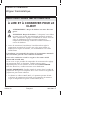
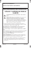
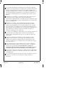
IMPORTANT INSTRUCTIONS
READ AND SAVE FOR THE
CONSUMER
WARNING: Risk of scalding or other severe injury.
CAUTION: Risk of scalding hazard. This device has been
calibrated at the factory to ensure a safe maximum water
temperature. Any variance in settings or water inlet
conditions from those used during factory calibration may
raise the discharge temperature above the safe limit, and may
present a scalding hazard.
•
Before completing installation, the installer must set the
maximum water temperature setting of this valve to minimize the
risks associated with scalding hazards according to ASTM F 444.
The installer is responsible for adjusting the maximum water
temperature of this valve according to instructions.
This valve meets or exceeds ANSI A112.18.1 and ASSE 1016.
If you do not understand any of the temperature adjustment
instructions in this document, in the United States please contact our
Customer Service Department at 1-800-4-KOHLER. Outside the U.S.,
please contact your distributor.
IMPORTANT NOTICE: Please fill in the blanks in the information box
in the Homeowners Guide and on the valve label. Retain the
Homeowners Guide for future reference.
•
The valve is calibrated to 104°F (40°C) at the first stop position,
and the maximum temperature limit stop is positioned so the
outlet water temperature does not exceed 120°F (49°C).
•
Factory calibrated inlet conditions are:
Hot and cold water pressure = 45 psi (3.2 kg/cm
2
)
Hot water supply temperature = 145°F (63°C)
Cold water supply temperature = 65°F (18°C)
•
If inlet conditions differ from those used during factory
calibration, it may be necessary to re-calibrate the valve after
installation. The installer must check the mixed flow
temperature after installation, and adjust the valve as needed
according to the instructions.
1041158-2-F 2 Kohler Co.

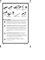
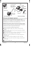
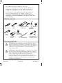
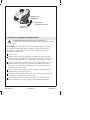
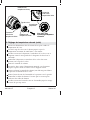
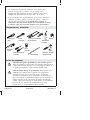
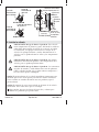
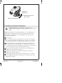
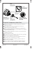
Tools and Materials
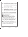
Before You Begin
DANGER: Risk of scalding or other severe injury. Before
completing installation, the installer must set the maximum
water temperature setting of this valve to minimize the risks
associated with scalding hazards according to ASTM F 444.
CAUTION: Risk of scalding. This device has been calibrated
at the factory to ensure a safe maximum water temperature.
Any variance in settings or water inlet conditions from those
used during factory calibration may raise the discharge
temperature above the safe limit, and may present a scalding
hazard. Responsibility for installation and adjustment of this
device in accordance with these instructions lies with the
installer.
CAUTION: Risk of product damage. This valve contains
plastic and rubber components. Do not sweat or braze
directly to the valve body. Do not apply excessive heat to the
valve body when you make solder connections. Do not apply
flux or acids directly to the valve, as damage to the seals,
plastic components, and trim finish may result.
CAUTION: Risk of product damage. Do not apply
petroleum-based lubricants to the valve components, as
damage may result.
Thermometer
Pipe
Wrench
Strap
Wrench
Adjustable
Wrench
Solder
Propane
Torch
Hacksaw or
Tubing Cutter
Thread
Sealant
Assorted
Screwdrivers
3/8" Socket
Wrench or Drive
Kohler Co. 3 1041158-2-F

Before You Begin (cont.)
CAUTION: Risk of product damage. Inlet and outlet
threaded joint connections should be made with plumbers
PTFE tape or liquid sealant. Oil-based, non-setting
compounds should not be used.
CAUTION: Risk of personal injury. The water temperature
should never be set above 120°F (49°C).
Observe all local plumbing and building codes.
Shut off the main water supply.
Inspect the supply piping for damage. Replace as necessary.
The bottom port of the thermostatic mixing valve is intended for
use as a bath filler only. If a bath spout is not used with this
product, cap the bottom port.
The K-669 and K-679 thermostatic mixing valves do not contain
an integral volume control/shut-off valve. You must install a
separate volume control/shut-off valve (K-671 or K-681)
downstream of any used valve outlet.
The K-670 and K-680 thermostatic mixing valves contain a single
volume control shut-off valve for controlling the water flow
through the shower outlet. When plumbing to the valve’s bath
outlet, you must install a separate volume control shut-off valve
(K-671 or K-681) downstream from the bath outlet.
The thermostatic mixing valves do not have an integral aspirator.
For installations that use a bath diverter spout, you must install a
twin ell (K-9663) with integral aspirator between the valve and
the bath spout. If these thermostatic mixing valves are installed
without an aspirator, it will cause water to flow from the shower
and bath spout at the same time.
Determine the correct drain size and capacity for your
installation. If two thermostatic mixing valves are used together,
water volumes between 18 and 30 gpm (60 and 114 lpm) or more
are possible, depending upon the water supply pressure.
Determine the correct water heater size and capacity for your
installation. A typical shower installation uses an approximate
mix of 75% hot water and 25% cold. A custom shower application
using three 2-1/2 gpm (9.5 lpm) showerheads can use about 45
gallons (170 liters) of hot water in 8 minutes. Choose a water
heater large enough for your installation.
1041158-2-F 4 Kohler Co.

Before You Begin (cont.)
The valve is calibrated to 104°F (40°C) at the first stop position.
The maximum temperature limit stop is positioned so the outlet
water temperature does not exceed 120°F (49°C).
The factory calibrated pressure for hot and cold water inlets is
43-1/2 psi (3 kg/cm squared). The factory calibrated hot water
supply temperature is 149°F (65°C) and the cold water supply
temperature is 59°F (15°C).
If the inlet conditions differ from those used during factory
calibration, it may be necessary to re-calibrate the valve after
installation. The installer must check the mixed flow
temperature after installation and adjust the valve as needed
according to the instructions.
This valve complies with ASME A112.18.1, ASSE 1016, and CSA
B125. The valve is listed with ASSE, CSA, and IAPMO/UPC.
If possible, flush all piping thoroughly before installing the valves
to prevent early clogging of filter screens.
Kohler Co. reserves the right to make revisions in the design of
faucets without notice, as specified in the Price Book.
Kohler Co. 5 1041158-2-F

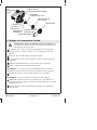
Composite Layout
H.
B.
A.
B.
B.
B.
B.
C.
D.
E.
F.
G.
I.
A.
J.
K.
A. K-669 or K-679 Thermostatic Mixer
B. K-671 or K-681 Volume Control
C. K-9663 Twin Ell (For use with Bath Diverter Spout)
D. Bath Spout with Diverter
E. Handshower
F. K-9660 Vacuum Breaker (for use with Handshower)
G. Bath Spout
H. K-672 3-Way Transfer Valve
I. Pressure Loop with Bodysprays
J. K-670 or K-680 Thermostatic Mixer with Volume Control
K. Showerhead
1041158-2-F 6 Kohler Co.

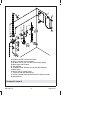
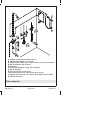
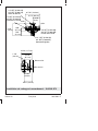
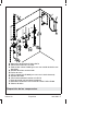
Framing and Rough Plumbing Installation - K-669/K-679
Max Finished Wall
Min Finished Wall
3-3/4" (9.5 cm)
2-7/16"
(6.2 cm)
1-1/8"
(2.9 cm)
3-7/16"
(8.7 cm)
4-5/8" (11.7 cm)
Stop
Stop
3-1/4" (8.3 cm)
1-3/16"
(3 cm)
6-7/16" (16.4 cm)
1-3/8"
(3.5 cm)
5-1/8"
(13 cm)
1-3/4"
(4.4 cm)
1/2" NPT (K-679-KS)
3/4" NPT (K-669-KS)
Hot Inlet
1/2" NPT (K-679-KS)
3/4" NPT (K-669-KS)
Shower Outlet
1/2" NPT (K-679-KS)
3/4" NPT (K-669-KS)
Cold Inlet
1/2" NPT (K-679-KS)
3/4" NPT (K-669-KS)
Bath Outlet
Kohler Co. 7 1041158-2-F

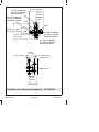
Frame and Rough Plumbing Installation - K-670/K-680
Stop
Stop
3-1/4"
(8.3 cm)
1-3/16"
(3 cm)
6-7/16" (16.4 cm)
3-1/8"
(7.9 cm)
6-15/16"
(17.6 cm)
Max Finished Wall
Min Finished Wall
1-3/4"
(4.4 cm)
1-3/8"
(3.5 cm)
1-3/16" (3 cm)
4-5/8"
(11.7 cm)
2-7/16"
(6.2 cm)
3-3/4" (9.5 cm)
3-7/16" (8.7 cm)
1/2" NPT (K-680-KS)
3/4" NPT (K-670-KS)
Hot Inlet
1/2" NPT (K-680-KS)
3/4" NPT (K-670-KS)
Shower Outlet
1/2" NPT (K-680-KS)
3/4" NPT (K-670-KS)
Cold Inlet
1/2" NPT (K-680-KS)
3/4" NPT (K-670-KS)
Bath Outlet
1041158-2-F 8 Kohler Co.

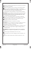
1. Prepare the Site
Determine the desired location for the valve according to the
rough-in information, and construct suitable stud and support
framing.
Depending upon the valve, use 1/2″ or 3/4″ nominal copper
tubing and fittings throughout this installation. Smaller diameter
piping upstream or downstream of the valve will reduce
performance of the valve.
Kohler Co. 9 1041158-2-F

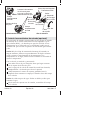
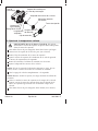
2. Install the Valve
CAUTION: Risk of product damage. This valve contains
plastic and rubber components. Do not sweat or braze
directly to the valve body. Do not apply excessive heat to the
valve body when you make solder connections. Do not apply
flux or acids directly to the valve or you may damage the
seals and plastic components.
CAUTION: Risk of product damage. Do not apply
petroleum-based lubricants to the valve components or
damage may result.
CAUTION: Risk of product damage. Inlet and outlet
threaded joint connections should be made with plumbers
PTFE tape or liquid sealant. Oil-based, non-setting
compounds should not be used.
NOTE: The bottom port of the thermostatic mixing valve is intended
for use as a bath filler only. If a bath spout is not used with this
product, cap the bottom port.
NOTE: A plaster guard is attached to the face of the mixing valve.
Do not remove it until instructed.
Flush the hot and cold water supply lines to remove any debris.
Install water hammer arrestors in the hot and cold water supply
lines.
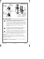
K-670 or K-680
K-669 or K-679
Hot Water
Supply Line
Cold Water
Supply Line
Hot Water
Supply Line
Cold Water
Supply Line
Plaster
Guard
Finished
Wall
If less than
3/16" (5 mm),
backing is
required.
Backing 1/2"
Plywood (Optional)
2-7/16"
(6.2 cm)
2-3/4" (7 cm)
1041158-2-F 10 Kohler Co.

Install the Valve (cont.)
Use thread sealant and connect the hot and cold water supply
lines to the valve inlet ports. Ensure that the corresponding water
supply lines are connected to the correct inlet ports.
NOTE: If the existing hot and cold plumbing makes this
configuration inconvenient or if it is advantageous to reverse the hot
and cold ports (such as back-to-back installations), see the ″Reversed
Inlet Supplies″ section.
For K-670 and K-680 valves, make certain that the integral
volume control/shut-off valve portion of the assembly is on top
when installed.
Connect the water outlet lines to the valve ports. Plug any
unused outlet port.
IMPORTANT! Secure the piping to the framing.
NOTE: When using the plaster guard to trace the cut-out, the tick
marks located outside of the guard will assist you in identifying the
spline centers.
Use the plaster guard to determine the depth of the valve in the
wall, and to trace the cut-out line in the wall material.
IMPORTANT! The finished wall must be within the MIN-MAX
depth shown on trim adapters 1, 2, and 3 of the plaster guard.
Turn on the water supply lines to the valves.
Run the water through the mixing valve, all showers, and the
spout.
Remove the plaster guard to access and inspect the valve.
Kohler Co. 11 1041158-2-F

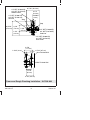
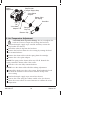
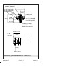
3. Reverse Inlet Supplies (optional)
The inlet connections are indicated on the inlet ports of the
thermostatic valve assembly. Left is HOT and right is COLD. If this
configuration is not suitable for your installation, the cartridge may
be rotated 180° to reverse the hot and cold inlet ports.
NOTE: DO NOT pull the removal clip from the cartridge assembly
at any time during this procedure. The retaining clip helps hold the
temperature limit stop and detent components in place and reduces
or eliminates the need for temperature adjustments.
With the valve already installed and pressurized:
Turn both integral supply stops until they contact the stop
bracket.
Turn the volume control valve stem (not shown) fully clockwise
to release the pressure.
Slowly loosen the head nut, turning it counterclockwise. This will
begin to draw the cartridge out of the valve body.
NOTE: Some water may be released. Use a bucket and towels to
contain the water.
Pull the head nut with the cartridge out of the valve body.
NOTE: Two seals may fall out when the cartridge is removed. Set
the seals aside.
Rotate the cartridge 180°.
Rotate 180˚.
Head Nut
Integral
Supply Stops
Valve Stem
Adapter
Seals
Cartridge
Tab
Rotate the CartridgeInlet Connections
Cartridge
Slot
Inlet
Port
Inlet
Port
On
Off
Stop Bracket
Body Fully
Threaded
Body Fully
Threaded
Lift service stop
tool to reveal
check valve/filter
screen body.
1041158-2-F 12 Kohler Co.

Reverse Inlet Supplies (optional) (cont.)
Verify the cold cartridge inlet is on the left when the valve stem
adapter is facing you.
NOTE: The hot and cold cartridge inlets are identified on the top
and sides of the cartridge tabs. The tabs are labeled ″H″ and ″C″ to
identify hot and cold.
Reinstall the seals onto each side of the cartridge.
Carefully push the cartridge back into the valve body. Make sure
both cartridge tabs are properly seated inside the cartridge slots
of the valve body.
Hand tighten the head nut onto the valve body. Do not
overtighten.
Return the integral supply stops back to their original position.
Kohler Co. 13 1041158-2-F

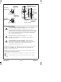
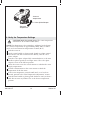
4. Verify the Temperature Settings
CAUTION: Risk of personal injury. The water temperature
should never be set above 120°F (49°C).
NOTE: The thermostatic valve cartridge is calibrated at the factory
for a shower temperature of approximately 104°F (40°C) to 105°F
(41°C) and a maximum hot temperature of 120°F (49°C).
Turn the water on.
Attach a trim handle or plaster guard (found in volume control
valve K-671 or K-681 or transfer valve K-672), onto the valve
spline adapter.
Turn the valve spline adapter fully counterclockwise so the trim
handle or plaster guard can no longer move. The valve spline
adapter is now in the full hot position.
Allow the water to run for several minutes to stabilize the water
supply temperatures.
Position a thermometer in the water stream to check the
temperature of the hot water.
If the water temperature exceeds 120°F (49°C) or is less than
desired, proceed to the ″Hot Temperature Adjustment″ section.
Turn the trim handle or plaster guard clockwise until you hear a
click. Do not turn any further. This is the shower temperature
position.
Valve Spline Adapter
Increase
temperature.
Decrease
temperature.
1041158-2-F 14 Kohler Co.

Verify the Temperature Settings (cont.)
Remove the trim handle or plaster guard from the valve spline
adapter.
Position a thermometer in the water stream to check the shower
temperature.
If the water temperature is less than 104°F (40°C) to 105°F (41°C)
or is more than desired, proceed to the ″Shower Temperature
Adjustment″ section.
If both settings are correct, fill out the ″Notice to Homeowners″
section of this Homeowners Guide.
Kohler Co. 15 1041158-2-F

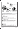
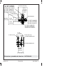
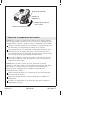
5. Hot Temperature Adjustment
CAUTION: Risk of product damage. Do not overtighten the
head nut. Excessive torque may damage the head nut.
Turn both integral supply stops outward until they contact the
stop bracket (not shown).
Detach the removal clip from the head nut.
Remove the head nut from the valve casting by turning the head
nut counterclockwise.
Remove the detent collar with the spring from the cartridge.
Remove the valve spline adapter.
NOTE: The spring on the detent collar may fall off. Reattach the
spring around the detent collar if this occurs.
Turn the valve stem fully counterclockwise.
NOTE: Leave the detent collar off while making adjustments.
Reinstall the head nut to the valve casting. Hand tighten the head
nut until the shoulder of the head nut contacts the lip of the
valve casting.
Turn both integral supply stops inward (not shown).
Turn on the water using the volume control valve (not shown).
Allow the water to flow for several minutes to stabilize the water
temperature.
Head Nut
Removal Clip
Removal
Clip Tab
Detent Collar
with Spring
Valve Spline
Adapter
Integral
Supply Stop
Stop Bracket
Integral Supply Stop
Valve Stem
Adapter Tab
Hot
Tab
1041158-2-F 16 Kohler Co.

6. Hot Temperature Adjustment (cont.)
Insert a thermometer into the water stream to verify the water
temperature.
Turn the valve stem clockwise until the maximum 120°F (49°C)
temperature is reached.
Reinstall the valve spline adapter with the adapter tab placed
flush against the left side of the hot tab on the cartridge.
Reinstall the valve spline adapter in this position over the valve
stem.
Shut off the volume control.
Turn both integral supply stops outward until they contact the
stop bracket.
Open and close the volume control (not shown) to relieve
pressure that has built up in the valve.
Remove the head nut from the assembly by turning the head nut
counterclockwise.
Reinstall the detent collar. Be sure the spring is resting on top of
the detent collar.
Reinstall the head nut onto the assembly until hand-tight. Do not
overtighten.
Valve Stem
Detent
Temperature
Limit Stop
Detent
Temperature
Limit Stop
Adapter
Assembly
Cartridge
High Temperature
Limit Stop
Cartridge
High Temperature
Limit Stop
Front View with Adapter
Assembly Reinstalled
Kohler Co. 17 1041158-2-F

Hot Temperature Adjustment (cont.) (cont.)
Reattach the removal clip to the head nut. The tab on the removal
clip should be facing inward.
Turn both integral supply stops inward.
Verify the temperature. Repeat the above steps if necessary.
Proceed to the ″Shower Temperature Adjustment″ section of this
guide.
1041158-2-F 18 Kohler Co.

7. Shower Temperature Adjustment
NOTE: To ensure the correct shower temperature, first turn the
valve spline adapter to the full hot position then adjust the shower
temperature.
Place the trim handle (not shown) or plaster guard (not shown)
onto the valve spline adapter.
Turn the valve spline adapter fully counterclockwise so the trim
handle or plaster guard can no longer move. The valve spline
adapter is now in the full hot position.
Turn the trim handle or plaster guard clockwise until you hear a
″click″. Do not turn any farther. This is the shower temperature
position.
NOTE: If a ″click″ is not heard or felt, detach the trim handle. Pull
out and rotate the detent collar 180° until it snaps back into place.
Reattach the trim handle and repeat the steps above to find the
shower temperature position.
Remove the trim handle or plaster guard from the valve spline
adapter.
Allow the water to run for a few minutes to stabilize the
temperature.
Hold a thermometer in the water stream to check the water
temperature.
If the temperature is less than 104°F (40°C):
Detent Collar
Valve Spline Adapter
Increase
temperature.
Decrease
temperature.
Kohler Co. 19 1041158-2-F

Shower Temperature Adjustment (cont.)
Pull out the detent collar.
Turn the detent collar counterclockwise.
Verify the temperature.
If the temperature is greater than 105°F (41°C):
Pull out the detent collar.
Turn the detent collar clockwise.
Verify the temperature.
Repeat the steps above until the desired temperature is achieved.
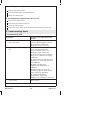
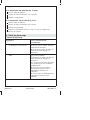
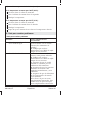
8. Troubleshooting Guide
Troubleshooting Table
Symptoms Probable Cause/Recommended
Action
1. Only hot or cold water from
the water outlet.
A. Inlet supplies are reversed. See
″Reverse Inlet Supplies″ section.
B. Check filter screens for
blockage. Clear if necessary.
2. Fluctuating or reduced flow
rate.
A. External condition variation
such as reduced pressure.
B. Check filter screens for
blockage. Clear if necessary.
C. Make sure that the minimum
flow rate is sufficient for supply
conditions.
D. Make sure that dynamic inlet
pressures are nominally balanced
and sufficient.
E. Make sure that inlet
temperature differentials are
sufficient.
F. Service stops are not fully
threaded in. Rotate both service
stops until fully threaded.
G. Check thermostatic
performance; replace the
thermostatic cartridge, if necessary.
3. No flow from shower control
water outlet.
A. Filter screens are blocked. Clear
filter screens.
1041158-2-F 20 Kohler Co.

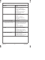
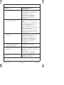
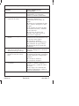
Troubleshooting Guide (cont.)
Symptoms Probable Cause/Recommended
Action
B. Hot or cold supply failure.
Replace the supply valve.
C. Flow control cartridge not
working. Check and replace if
necessary.
D. Service stops are shut off.
Rotate both service stops
counterclockwise.
4. Blend temperature drift. A. Indicates operating conditions
have changed. No action is
needed.
B. Refer to symptom 2.
C. Hot supply temperature
fluctuation.
D. Supply pressure fluctuation.
5. Hot water in cold supply or
cold water in hot supply.
A. Indicates crossflow. Replace
check valve.
6. Maximum blend temperature
setting too hot or too cold.
A. Indicates incorrect maximum
temperature setting; refer to the
″Hot Temperature Adjustment″
section.
B. Refer to symptom 4.
C. Refer to symptom 5.
7. Water leaking from the valve
body.
A. Seal(s) worn or damaged.
Obtain service kit and replace
seal(s).
B. If leaking from around the
temperature spindle, replace the
thermostatic cartridge.
8. Flow knob or temperature
knob is stiff to operate.
A. Impaired free movement of
internal components. Replace the
appropriate cartridge.
B. Supply pressures are too high.
Fit pressure reducing valve.
Kohler Co. 21 1041158-2-F
Page is loading ...
Page is loading ...
Page is loading ...
Page is loading ...
Page is loading ...
Page is loading ...
Page is loading ...
Page is loading ...
Page is loading ...
Page is loading ...
Page is loading ...
Page is loading ...
Page is loading ...
Page is loading ...
Page is loading ...
Page is loading ...
Page is loading ...
Page is loading ...
Page is loading ...
Page is loading ...
Page is loading ...
Page is loading ...
Page is loading ...
Page is loading ...
Page is loading ...
Page is loading ...
Page is loading ...
Page is loading ...
Page is loading ...
Page is loading ...
Page is loading ...
Page is loading ...
Page is loading ...
Page is loading ...
Page is loading ...
Page is loading ...
Page is loading ...
Page is loading ...
Page is loading ...
Page is loading ...
Page is loading ...
Page is loading ...
Page is loading ...
Page is loading ...
Page is loading ...
Page is loading ...
Page is loading ...
-
 1
1
-
 2
2
-
 3
3
-
 4
4
-
 5
5
-
 6
6
-
 7
7
-
 8
8
-
 9
9
-
 10
10
-
 11
11
-
 12
12
-
 13
13
-
 14
14
-
 15
15
-
 16
16
-
 17
17
-
 18
18
-
 19
19
-
 20
20
-
 21
21
-
 22
22
-
 23
23
-
 24
24
-
 25
25
-
 26
26
-
 27
27
-
 28
28
-
 29
29
-
 30
30
-
 31
31
-
 32
32
-
 33
33
-
 34
34
-
 35
35
-
 36
36
-
 37
37
-
 38
38
-
 39
39
-
 40
40
-
 41
41
-
 42
42
-
 43
43
-
 44
44
-
 45
45
-
 46
46
-
 47
47
-
 48
48
-
 49
49
-
 50
50
-
 51
51
-
 52
52
-
 53
53
-
 54
54
-
 55
55
-
 56
56
-
 57
57
-
 58
58
-
 59
59
-
 60
60
-
 61
61
-
 62
62
-
 63
63
-
 64
64
-
 65
65
-
 66
66
-
 67
67
-
 68
68


Kohler K-680-KS-NA Installation guide
- Category
- Sanitary ware
- Type
- Installation guide
Ask a question and I''ll find the answer in the document
Finding information in a document is now easier with AI
in other languages
- français: Kohler K-680-KS-NA Guide d'installation
- español: Kohler K-680-KS-NA Guía de instalación
Related papers
-
Kohler K-2973-KS-NA Installation guide
-
Kohler 2973-KS-NA Installation guide
-
-
Kohler K-T10681-4-BV Installation guide
-
-
-
-
-
-
Other documents
-
IKEA Plumbing Product AA-220170-3 User manual
-
-
-
-
-
-
-
-
-