
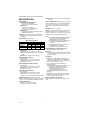
INSTALLATION INSTRUCTIONS
62-0311—13
TB6575/TB8575 Digital Fan Coil
Thermostats
PRODUCT DESCRIPTION
The TB6575 and TB8575 are a family of Digital Fan Coil
thermostats for residential and commercial applications
such as hotels, condominiums, school classrooms, etc.
Four models are available for your application:
• TB6575A1016 – 2-pipe or 4-pipe with seasonal/
manual/automatic heat/cool changeover; 120/240
Vac.
• TB6575B1000 – 2-pipe only with seasonal or manual
heat/cool changeover; 120/240 Vac.
• TB6575C1016 – 2-pipe or 4-pipe with seasonal/
manual/automatic heat/cool changeover; 120/240/
277 Vac.
• TB8575A1016 – 2-pipe or 4-pipe with seasonal heat/
cool changeover; 24Vac.
All four models are suitable for multiple applications.
Changes in output wiring and external links between
wiring terminals allow you to configure the thermostat for
the appropriate application.
The applications that are available are:
• Heating or Cooling only
• Two pipes: Heat or Cool with Manual Changeover
• Two pipes: Heat or Cool with Seasonal Changeover
(requires optional pipe sensor)
• Two pipes: Heat or Cool with Auxiliary Heat and
Manual or Seasonal Changeover (requires optional
pipe sensor)
• Four pipes: Mixed Manual and Auto Changeover
• Four pipes: Manual Changeover
• Four pipes: Auto Changeover
The fan is controlled from the thermostat. The Low,
Medium, High, or Auto fan settings are easily made with
a press of a key.
Valves and auxiliary electric heaters can be controlled
using a relay or contactor controlled by the system
switch.
FEATURES
• Simple, intuitive user interface.
• Pre-installed lead wires for fast installation
(TB6575A, TB6575B and TB6575C models only)
• Backlight display permits easy viewing in any
light.
• Four buttons allow manual control of system
operation, fan speed, and temperature setpoint
adjustment.
• Digital display of ambient temperature, setpoint,
heating or cooling mode, fan status, and remote
setback
• Proportional plus Integral (P+I) control algorithm
for precision temperature regulation.
• Single Setpoint and Heat/Cool setpoint methods
for 4-pipe auto changeover.
• Adjustable maximum heating and minimum
cooling setpoint limits using range stops.
• EEPROM permanently retains user settings,
including setpoints, during power loss (no
batteries required).
• Selectable °C or °F display via Setup button on
thermostat.
• Displayable pipe sensor temperature readout to
aid in troubleshooting.
• Selectable to allow the fan motor to always begin
on high speed to ensure sufficient torque at
startup.
• Option to wire a remote indoor temperature
sensor.
• Freeze protect algorithm turns on heat when
needed.
• Economy Setback options via dry contact or
Activity Sensing
• Advanced fan control with VersaSpeed™ fan ramp
algorithm and Auto Fan Reset

TB6575/TB8575 DIGITAL FAN COIL THERMOSTATS
62-0311—13 2
SPECIFICATIONS
Supply Voltages:
TB6575A1016 and TB6575B1000:
• 120 Vac ±10% at 50/60Hz
• 240 Vac -15% to +10% at 50/60Hz
TB6575C1016:
• 120 Vac ±10% at 50/60Hz
• 240 Vac -15% to +10% at 50/60Hz
• 277 Vac ±10% at 50/60Hz
TB8575A1016:
• 20 to 30 Vac at 50/60Hz (using 24 Vac, Class 2,
NEMA rated transformer)
Safety Fuse: 15 A, 350V. If the safety fuse blows, the
thermostat must be replaced. The fuse is not field
replaceable.
Electrical Ratings: (see Table 1).
Environmental Ratings:
Temperature:
Operating Range: 18°C to 49°C (0°F to 120°F).
Shipping and Storage Range: -29°C to 49°C (-20°F to
120°F).
Humidity: 5% to 90% RH, non-condensing.
Onboard Temperature Sensor:
Ty p e : 1 0 K N T C
Working Range: 18°C to 49°C (0°F to 120°F)
Display Range: 0°C to 37°C (32°F to 99°F)
Accuracy ±2.0°F at 70°F
Remote Temperature Sensor (optional):
Ty p e : 2 0 K N T C
Working Range: 18°C to 49°C (0°F to 120°F)
Display Range: 0°C to 37°C (32°F to 99°F)
Accuracy ±2.0°F at 70°F
Remote Pipe Sensor (optional):
Ty p e : 2 0 K N T C
Working Range: 0°C to 93°C (32°F to 199°F)
Display Range: 0°C to 93°C (32°F to 199°F)
Accuracy ±5.0°F over the temperature sensing range
Remote Setback Input: Dry contact, maximum
resistance of 100 ohms. TB6575 – 9Vdc, < 4 mA; TB8575
– 16 Vdc, < 5 mA. Note Electrical WARNING on page 3.
Remote Setback Range:
Heating: 10°C to 21°C (50°F to 70°F).
Cooling: 22°C to 32°C (72°F to 90°F).
Enclosure: Plastic (cover, sub-base, and optional adap-
tor plate)
Junction Box Mounting: Direct mounting on a horizontal
single gang NEMA 2 x 4 in. surface mount electrical box,
or on 4 x 4 in. box or vertical 2 x 4 in. surface mount
electrical box with the optional 50033847-001 adapter
plate.
Dimensions: See Fig. 1 on page 3.
Wiring: 11 screw-in terminals located on the sub-base
capable of accepting up to 2 x 18 AWG (0.8 sq. mm), 1 x
16 AWG (1.3 sq. mm), or 1 x 14 AWG (2.1 sq. mm) wires.
Accepts stranded or unstranded 14-28 gauge wire.
NOTES:
1. The TB6575A1016 and TB6575C1016 models
are pre-fitted with color-coded fly leads (16
AWG) attached to seven terminals.
2. The TB6575B1000 model is pre-fitted with color-
coded fly leads (16 AWG) attached to six
terminals.
3. The TB8575A1016 model does not have fly
leads attached to any terminals.
4. See Table 3 on page 5 for fly lead usage.
Minimum Operational Life (at maximum load):
Thermostat contacts: 100,000 cycles
Approvals:
CSA Certified C/US for Canada and the U.S.A. Meets
the same requirements as UL-873 and UL 1/4 HP.
FCC Part 15 Class B
Accessories:
• 50033847-001 – Adapter plate for mounting on a
vertical 2 x 4 in. single-gang or double-gang NEMA
standard vertical switch box (6 1/4 in. (158 mm) x 5 1/
16 in. (128 mm) x 13/22 in. (10 mm)).
• TR21 – 20K Ohm NTC Non-Linear Remote
temperature sensor.
Other acceptable remote temperature sensors are —
• 20K Ohm: C7041B2005, C7041B2013,
C7041C2003, C7041P2004, C7770A1006,
C7772A1004, and C7772A1012
• 10K Ohm (for averaging only): TR21-A
• PS20 (535-34AB08-203) – Remote pipe sensor
(20K Ohm)
• W6380B1005 – Fan Coil Unit Relay Control Center
• WSK-24 - Wireless Occupancy Solution (Receiver,
occupancy sensor and door sensor)
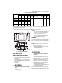
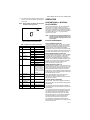
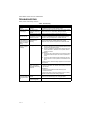
Models, applications, and features:
Table 2 identifies the applications and features of each
model.
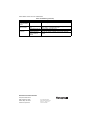
Table 1. Electrical Ratings.
Component
Amps (inductive) for:
24 Vac 120 Vac 240 Vac 277 Vac
Fan Relay 1.0 A 6.0 A 3.0 A 2.4 A
Heat/Cool Relay 1.0 A 1.0 A 1.0 A 1.0 A

TB6575/TB8575 DIGITAL FAN COIL THERMOSTATS
3 62-0311—13
Table 2. Applications and Features
Fig. 1. Dimensions in inches (mm).
INSTALLATION
When Installing this Product…
1. Read these instructions carefully. Failure to follow
them could damage the product or cause a hazard-
ous condition.
2. Check the ratings given in the instructions and on
the product to make sure the product is suitable for
your application.
3. Installer must be a trained and experienced service
technician.
WARNING
Risk of electrical shock.
Can cause severe injury, property damage or
death.
Disconnect power supply before installation and
before servicing.
IMPORTANT
The thermostats are line voltage powered devices. All
wiring must comply with national and local electrical
codes, ordinances and regulations. Provide disconnect
means and overload protection, as required.
The TB8575A1016 thermostat must be powered by an
Approved 24 Vac, Class 2, NEMA rated transformer
(such as a W6380 Relay Control Center).
Location
The thermostats are the temperature control element in a
fan coil or air-conditioning system. They must be located
about 1.5m (5 ft.) above the floor, in a position with good
air circulation, to sense room temperature.
IMPORTANT
Do not mount the device where it can be affected by:
1. Drafts or dead spots behind doors or in corners.
2. Hot or cold air from ducts.
3. Radiant heat from the sun or appliances.
4. Unheated (uncooled) areas such as an outside
wall behind the thermostat.
5. Concealed pipes or chimneys.
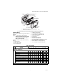
Mounting and Wiring
CAUTION
Equipment damage hazard.
Operation at low temperatures can cause fan
coil damage.
This thermostat is not a safety device. Do not use
it where the space temperature is outside of the
device operating range.
A display of two dashes, – –, for the Room Temp
display indicates a sensor failure or a temperature
outside of the thermostat operating range of 18°C
to 49°C (0°F to 120°F). With – – displayed, the
thermostat ceases to operate. When the
temperature returns to within its operating limits,
the thermostat returns to operation.
The optional freeze protect feature should be used
if low temperatures can occur.
The thermostat must be mounted flush to the wall. The
thermostat can be mounted directly to a 2 x 4 in.
horizontal junction box (see Fig. 2 on page 4). An optional
Models
Applications Features
Heat/Cool/
Auto
Pipes Voltage Number
of Relays
a
a
The five relays are wired via terminals W, Y, Gh, Gm, and Gl. Relay 1 controls Heat open (W) or Cool open (Y). Relay
2 controls Cool open or Electrical heater output (Y/A). Relays 3, 4, and 5 control the High, Medium, and Low fan
speeds respectively (Gh, Gm, and Gl).
NOTE: In 2-pipe configurations without Auxiliary Heat, only 4 relays are used; relay 2 (Y/A) is not used.
Energy
Savings
Input
Fan: On,
Auto, or 3
speed
Manual/
Auto
Changeover
Remote
Sensor
Back
Light
Pipe
Sensor
b
b
Pipe sensor is required for 2 pipe auto changeover and 2 pipe auxiliary heat applications.
TB6575A1016 All 2 or 4 120 or
240 Vac
5
Ye s Ye s Ye s Ye s Ye s Ye s
TB6575B1000 Heat or
Cool
2120 or
240 Vac
4
TB6575C1016 All 2 or 4 120, 240
or 277
Vac
5
TB8575A1016 All 2 or 4 24 Vac 5
M27589
UP
5-13/16 (148)
3-13/16
(97)
1-1/8
(29)
THERMOSTAT
SUB-BASE
3-1/4 (83)
2-3/8 (60)
1-3/4
(44)
5/32
(4)
5/32
(4)
1-3/16
(30)

TB6575/TB8575 DIGITAL FAN COIL THERMOSTATS
62-0311—13 4
adaptor plate (50033847-001) can be used with a 4 x 4 in.
or a vertical junction box for which mounting screws are
supplied (see Fig. 3 on page 5).
1. Prepare the supply wires:
a. Mounting on a 4 x 4 in. or vertical 2 x 4 in.
junction box:
(1) Feed the supply wires through the junction
box and the opening in the adaptor plate.
(2) Affix the adaptor plate to the junction box
using the screws provided.
b. Mounting on a horizontal 2 x 4 in. junction box:
Feed the supply wires through the opening of the
junction box.
2. Attach the supply wires:
a. For the TB6575A1016,TB6575B1000 and
TB6575C1016 models:
(1) Push the fly lead wires through the wiring
access hole in the sub-base.
(2) Attach the fly lead wires to the supply wires
using wire nuts (not provided).See Table 3
on page 5 for terminal and lead identifica-
tion.
(3) Push the fly lead and supply wires back into
the junction box.
b. For the TB8575A1016 model (which does not
have pre-wired fly leads):
(1) Attach the supply wires directly to the termi-
nals on the sub-base. See Table 3 on page 5
for terminal identification.
(2) Push the supply wires back into the junction
box.
3. Mount the sub-base:
a. Mounting on a 4 x 4 in. or vertical 2 x 4 in. junc-
tion box:
Align the two holes at the top edges of the sub-
base with the two pins on the adaptor plate.
Attach the sub-base to the adaptor plate using
the screws provided.
b. Mounting on a horizontal 2 x 4 in. junction box:
Attach the sub-base to the junction box using the
screws provided.
4. Thoroughly check the wiring to the sub-base before
finally mounting the thermostat on the wall.
5. Center the thermostat body over the sub-base, and
press down firmly to engage the four tabs on the
sub-base and snap the thermostat body into place.
6. Use the provided safety screw to secure the ther-
mostat main body to the sub-base.
7. If using the adaptor plate, press the adaptor plate
screw cover into place.
Fig. 2. Mounting sub-base and thermostat to 2 x 4 in. junction box.
M27590
INSERT SCREW TO LOCK
MAIN BODY TO SUBBASE
SNAP MAIN BODY
ONTO SUBBASE
MOUNT SUBBASE TO
HORIZONTAL 2X4
JUNCTION BOX USING
TWO SCREWS
SUBBASE

TB6575/TB8575 DIGITAL FAN COIL THERMOSTATS
5 62-0311—13
Fig. 3. Mounting sub-base and thermostat using the adaptor plate (50033847-001).
Terminal Wiring
Table 3 provides the terminal wiring for each model and
application.
NOTE: The TB6575A1016,TB6575B1000 and
TB6575C1016 models have color coded fly
leads attached to the terminals. Refer to
Table 3 for the color codes.
The Terminal Identifiers in Table 3 have the following
meaning:
• C: Common 24 Vac
• Gh: High speed fan relay
• Gl: Low speed fan relay
• Gm: Medium speed fan relay
• L: Line voltage power (120/240/277 Vac)
• N: Line voltage ground (120/240/277 Vac)
• Ps: Pipe sensor (optional)
• R: 24 Vac power
• Rs: Remote sensor (optional)
• SB: Remote setback (optional)
• Sc: Ground (required if remote sensor, pipe sensor,
and/or remote setback are connected)
• W/Y: W = Heating; Y = Cooling (2 pipe only)
• Y/A: Y = Cooling; A = Electrical heater output
M27591
INSERT SCREW
TO LOCK MAIN
BODY TO
SUB-BASE
SNAP MAIN BODY
ONTO SUB-BASE
SUB-BASE
MOUNT ADAPTOR PLATE ONTO
4X4 WIRING BOX OR 2X4
VERTICAL JUNCTION BOX
USING TWO SCREWS
ADAPTOR
PLATE
SCREW HEAD
COVER
ADAPTOR
PLATE
MOUNT SUB-BASE
ONTO WALL PLATE
USING TWO SCREWS
NOTE: MIDDLE HOLES OF ADAPTOR PLATE ARE USED FOR MOUNTING
TO A 2X4 VERTICAL JUNCTION BOX. USE OUTER HOLES FOR
MOUNTING TO A 4X4 WIRING BOX.
Table 3. Terminal Wiring.
Model Application
Terminals
12 34567891011
TB6575A1016 — 120/240 Vac;
TB6575C1016 — 120/240/277 Vac
Terminal Identifier
LW/Y Y/AGlGmGhNRs
a
Sc
b
SB
c
Ps
d
Fly lead wire color
Black Orange Yellow Red Blue Brown White None
e
2 pipes; Heat only
f
W
O
g
R
h
O
2 pipes; Cool only Y
ORO
2 pipes; Heat or Cool with Manual Changeover W/Y
ORO
2 pipes; Heat or Cool with Seasonal Changeover W/Y
ORO
4 pipes; Heat and Cool with Manual Changeover WY
ORO
4 pipes; Heat and Cool with Auto Changeover WY
ORO
2 pipes; Heat or Cool with Auxiliary Heat W/Y A
ORO
4 pipes; Heat and Cool with Manual Changeover
or Auto Changeover
WY
ORO
TB6575B1000 — 120/240 Vac

TB6575/TB8575 DIGITAL FAN COIL THERMOSTATS
62-0311—13 6
Terminal Identifier
LW/Y n/a
i
Gl Gm Gh N Rs
a
Sc
b
SB
c
Ps
d
Fly lead wire color
Black Orange Red Blue Brown White None
e
2 pipes; Heat only W
ORO
2 pipes; Cool only Y
ORO
2 pipes; Heat or Cool with Manual Changeover W/Y
ORO
2 pipes; Heat or Cool with Seasonal Changeover W/Y
ORO
TB8575A1016 — 24 Vac
Terminal Identifier
j
RW/YY/AGlGmGh CRs
a
Sc
b
SB
c
Ps
d
2 pipes; Heat only W
ORO
2 pipes; Cool only Y
ORO
2 pipes; Heat or Cool with Manual Changeover W/Y
ORO
2 pipes; Heat or Cool with Seasonal Changeover W/Y
ORO
4 pipes; Heat and Cool with Manual Changeover WY
ORO
4 pipes; Heat and Cool with Auto Changeover WY
ORO
2 pipes; Heat or Cool with Auxiliary Heat W/Y A
ORO
4 pipes; Heat and Cool with Manual Changeover
or Auto Changeover
WY
ORO
a
Rs; Remote sensor is optional.
b
Required when Rs, SB, or Ps is wired.
c
SB; Remote setback is optional.
d
Pipe sensor: Discrete, Analog, or Aquastat®.
e
These terminals (8, 9, 10, and 11) do not have lead wires attached to them.
f
A check mark (ü) indicates the terminal is used in that application. Rs and SB terminal connections are optional. If a
terminal is left blank, it is not used in that application.
g
O = Optional
h
R = Required if Rs, SB, or Ps is wired.
i
Terminal 3 is not used on the TB6575B1000 model.
j
The TB8575A1016 model does not have fly lead wires attached to any terminals.
Table 3. Terminal Wiring. (Continued)
Model Application
Terminals
12 34567891011

TB6575/TB8575 DIGITAL FAN COIL THERMOSTATS
7 62-0311—13
Accessory Wiring
Remote Pipe Sensor Wiring
The remote pipe sensor is used for 2 pipes auto and 2
pipes heat and cool with auxiliary heat changeover. The
pipe sensor will sense the temperature in the pipes to tell
the thermostat when the system is set for Heat or Cool.
1. Check Installer Setup Number (IS) 5 to ensure it is
set to the desired value. (See Table 4 on page 11).
2. Wire pipe sensor to Sc and Ps terminals.
3. Attach pipe sensor to the pipe.
4. Insulate pipe sensor, as necessary.
5. Change pipe sensor thresholds for cooling or heat-
ing by setting Installer Setup Numbers (IS) 6 and 7
to desired values.
Remote Temperature Sensor Wiring
The TR21 is an optional remote temperature sensor that
can be used as an alternative to the internal sensor. In
addition to the TR21, other sensors that use a 20k Ohm
curve may be used as the remote sensor.
WARNING
Risk of electrical shock.
Can cause severe injury, property damage or
death.
Disconnect power supply before servicing.
CAUTION
Erratic system operation hazard.
Failure to follow proper wiring practices can
introduce disruptive electrical interference
(noise).
Keep wiring at least one foot away from large
inductive loads such as motors line starters,
lighting ballasts, and large power distribution
panels. Shielded cable is required in installations
where these guidelines cannot be met. Ground
shield only to grounded controller case.
IMPORTANT
All wiring must comply with local electrical codes and
ordinances or as specified on installation wiring dia-
grams.
— Wall module wiring can be sized from 16 to 22
AWG (1.31 to 0.33 sq. mm) depending on the
application.
— The maximum length of wire from the thermostat
to a wall module is 1000 ft. (305 m).
— Twisted pair wire is recommended for wire runs
longer than 100 ft. (30.5 m).
1. Check Installer Setup Number (IS) 4 to ensure it is
set to use the remote sensor. (See Table 4 on
page 11).
2. Wire sensor to Rs and Sc thermostat terminals.
3. Push excess wire back into the hole. Plug the hole
using non-hardening caulk, putty or insulation to
prevent drafts from affecting performance.
4. Remove sensor cover.
5. Mount sensor to the wall or junction box using the
screws and anchors provided.
6. Level the sensor for appearance only. Device func-
tions correctly even when not level.
7. Replace sensor cover.
NOTE: For complete wiring instructions, please
follow the installation instructions provided
with the remote sensor.
Sensor Wiring for Temperature
Averaging
Fig. 4–Fig. 6 illustrate sensor wiring for temperature
averaging applications.
Fig. 4. Wiring four TR21 (20K ohm) sensors.
Fig. 5. Wiring two TR21-A (10K ohm) sensors to
provide a temperature averaging network.
Fig. 6. Wiring two TR21 (20K ohm) sensors and
one TR21-A (10K ohm) sensor to provide
a temperature averaging network.
M27559
Rs Sc
T T
SUBBASE
TR21
T T
TR21
T T
TR21
T T
TR21
M27560
Rs
Sc
SUBBASE
TR21-A
T4 T3
TR21-A
T4 T3
1
11
THE TR21-A IS A 10K OHM SENSOR.
M27561
T4
T3
TR21-A
1
1
THE TR21-A IS A 10K OHM SENSOR.
Rs
Sc
T
T
SUBBASE
TR21
TT
TR21

TB6575/TB8575 DIGITAL FAN COIL THERMOSTATS
62-0311—13 8
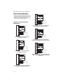
Thermostat Wiring Diagrams
The figures in this section illustrate typical wiring for:
• TB6575A1016,TB6575B1000 and TB6575C1016 fan
coil thermostats, which are 120/240/277 Vac powered.
Refer to Fig. 7–Fig. 13, beginning on page 8.
• TB8575A1016 model, which is 24 Vac powered. Refer
to Fig. 14–Fig. 20, beginning on page 9.
120/240/277 Vac Wiring Diagrams
(TB6575A/B/C)
Fig. 7. Two pipes Heat-only wiring diagram
(120/240/277 Vac shown).
Fig. 8. Two pipes Cool-only wiring diagram
(120/240/277 Vac shown).
Fig. 9. Two pipes (Heat or Cool) Manual Changeover
wiring diagram (120/240/277 Vac shown).
Fig. 10. Two pipes (Heat or Cool) Auto Changeover
wiring diagram (120/240/277 Vac shown).
Fig. 11. Four pipes (Heat and Cool) Manual/Auto
changeover wiring diagram (120/240/277 Vac shown).
Fig. 12. Two pipes (Heat or Cool) with Auxiliary Heat
and Manual Changeover wiring diagram (120/240/277
Vac shown).
L
W/Y
Y/A
GI
Gm
Gh
N
Rs
Sc
SB
Ps
N
L (HOT)
M27566
REMOTE SENSOR
REMOTE SETBACK
HEAT VALVE
FAN
N
L (HOT)
M27567
REMOTE SENSOR
REMOTE SETBACK
COOL VALVE
FAN
L
W/Y
Y/A
GI
Gm
Gh
N
Rs
Sc
SB
Ps
N
L (HOT)
M27568
REMOTE SENSOR
REMOTE SETBACK
VALVE
FAN
L
W/Y
Y/A
GI
Gm
Gh
N
Rs
Sc
SB
Ps
N
L (HOT)
M27569
REMOTE SENSOR
REMOTE SETBACK
VALVE
FAN
PIPE SENSOR
L
W/Y
Y/A
GI
Gm
Gh
N
Rs
Sc
SB
Ps
N
L (HOT)
M27570
REMOTE SENSOR
REMOTE SETBACK
HEAT VALVE
FAN
COOL VALVE
L
W/Y
Y/A
GI
Gm
Gh
N
Rs
Sc
SB
Ps
N
L (HOT)
M27571
REMOTE SENSOR
REMOTE SETBACK
VALVE
FAN
AUX
PIPE SENSOR
L
W/Y
Y/A
GI
Gm
Gh
N
Rs
Sc
SB
Ps

TB6575/TB8575 DIGITAL FAN COIL THERMOSTATS
9 62-0311—13
.
Fig. 13. Wiring diagram when missing a wire for
electromechanical retrofit (120/240/277 Vac shown).
24 Vac Wiring Diagrams (TB8575)
For the TB8575A1016 model, a 24 Vac Class 2 NEMA
rated transformer must be used.
Fig. 14. Two pipes Heat-only wiring diagram (24 Vac
shown).
Fig. 15. Two pipes Cool-only wiring diagram (24 Vac
shown).
Fig. 16. Two pipes (Heat or Cool) Manual Changeover
wiring diagram (24 Vac shown).
Fig. 17. Two pipes (Heat or Cool) auto changeover
wiring diagram (24 Vac shown).
Fig. 18. Four pipes (Heat and Cool) Manual/Auto
Changeover wiring diagram (24 Vac shown).
M31328A
HEAT VALVE
FAN
COOL VALVE
REMOTE SETBACK
REMOTE SENSOR
L (HOT)
3
4
5
5
1
2
1
2
REMOVE PRE-WIRED WIRE FROM TERMINAL 5 (MID FAN SPEED).
JUMPER TERMINALS 5 AND 6 (MID AND HIGH FAN SPEEDS). FAN
MEDIUM SETTING WILL OPERATE ON HIGH SPEED.
CONNECT TERMINAL 7 TO THE MID FAN SPEED WIRE FROM THE
PREVIOUS SYSTEM.
REWIRE THE PREVIOUS MID SPEED FAN WIRE TO THE NEUTRAL
CIRCUIT IN THE SYSTEM.
CHANGE INSTALLER SETUP IS CODE 9 TO 2 FOR 2 SPEED FAN
CONTROL.
3
4
N
L
W/Y
Y/A
GI
Gm
Gh
N
Rs
Sc
SB
Ps
24 VAC
M27573
HEAT VALVE
FAN
L1
(HOT)
L2
1
REMOTE SENSOR
REMOTE SETBACK
1
POWER SUPPLY. PROVIDE DISCONNECT MEANS AND
OVERLOAD PROTECTION AS REQUIRED.
R
W/Y
Y/A
GI
Gm
Gh
C
Rs
Sc
SB
Ps
24 VAC
M27574
COOL VALVE
FAN
L1
(HOT)
L2
1
REMOTE SENSOR
REMOTE SETBACK
1
POWER SUPPLY. PROVIDE DISCONNECT MEANS AND
OVERLOAD PROTECTION AS REQUIRED.
R
W/Y
Y/A
GI
Gm
Gh
C
Rs
Sc
SB
Ps
24 VAC
M27575
VALVE
FAN
L1
(HOT)
L2
1
REMOTE SENSOR
REMOTE SETBACK
1
POWER SUPPLY. PROVIDE DISCONNECT MEANS AND
OVERLOAD PROTECTION AS REQUIRED.
R
W/Y
Y/A
GI
Gm
Gh
C
Rs
Sc
SB
Ps
24 VAC
M27576
VALVE
FAN
L1
(HOT)
L2
1
REMOTE SENSOR
REMOTE SETBACK
1
POWER SUPPLY. PROVIDE DISCONNECT MEANS AND
OVERLOAD PROTECTION AS REQUIRED.
PIPE SENSOR
R
W/Y
Y/A
GI
Gm
Gh
C
Rs
Sc
SB
Ps
24 VAC
M27577
HEAT VALVE
FAN
L1
(HOT)
L2
1
REMOTE SENSOR
REMOTE SETBACK
1
POWER SUPPLY. PROVIDE DISCONNECT MEANS AND
OVERLOAD PROTECTION AS REQUIRED.
COOL VALVE
R
W/Y
Y/A
GI
Gm
Gh
C
Rs
Sc
SB
Ps

TB6575/TB8575 DIGITAL FAN COIL THERMOSTATS
62-0311—13 10
Fig. 19. Two pipes (Heat or Cool) with Auxiliary Heat
and Manual Changeover wiring diagram (24 Vac
shown).
.
Fig. 20. Wiring diagram when missing a wire for
electromechanical retrofit (24 Vac shown).
Removing the Thermostat
WARNING
Risk of electrical shock.
Can cause severe injury, property damage or
death.
Disconnect power supply before servicing.
CAUTION
Equipment damage hazard.
Improper removal can damage the thermostat.
Carefully follow the thermostat removal directions.
If it is necessary to remove the thermostat from the sub-
base, refer to Fig. 21 and perform the following steps:
1. Turn off the thermostat by pressing the system
button until OFF displays.
2. Remove the power source from the thermostat.
3. Remove the small safety screw at the bottom of the
thermostat.
4. Use both hands to pull the thermostat straight away
from the sub-base.
Fig. 21. Removing the thermostat.
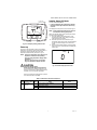
SETUP
The thermostat provides an LCD display, two buttons
below the display for System and Fan control and two
adjustment buttons (Up and Down) to the right of the
display. See Fig. 23.
Settings, including setpoints, are permanently retained in
EEPROM in case of a power outage.
Fig. 22 illustrates all the possible LCD display elements.
Only those elements pertinent to the current settings and
status (including the text for the two buttons, System and
Fan), actually display.
Fig. 22. LCD display with all possible elements
shown.
24 VAC
M27578
VALVE
FAN
L1
(HOT)
L2
1
REMOTE SENSOR
REMOTE SETBACK
1
POWER SUPPLY. PROVIDE DISCONNECT MEANS AND
OVERLOAD PROTECTION AS REQUIRED.
PIPE SENSOR
AUX
R
W/Y
Y/A
GI
Gm
Gh
C
Rs
Sc
SB
Ps
24 VAC
M31329A
HEAT VALVE
FAN
COOL VALVE
REMOTE SETBACK
REMOTE SENSOR
L1
(HOT)
L2
5
3
4
1
2
1
2
REMOVE PRE-WIRED WIRE FROM TERMINAL 5 (MID FAN SPEED).
JUMPER TERMINALS 5 AND 6 (MID AND HIGH FAN SPEEDS). FAN
MEDIUM SETTING WILL OPERATE ON HIGH SPEED.
CONNECT TERMINAL 7 TO THE MID FAN SPEED WIRE FROM
PREVIOUS SYSTEM.
REWIRE THE PREVIOUS MID FAN SPEED WIRE TO THE NEUTRAL
CIRCUIT IN THE SYSTEM.
POWER SUPPLY. PROVIDE DISCONNECT MEANS AND OVERLOAD
PROTECTION AS REQUIRED.
CHANGE INSTALLER SETUP IS CODE 9 TO 2 FOR 2 SPEED FAN
CONTROL.
3
4
5
6
6
L
W/Y
Y/A
GI
Gm
Gh
C
Rs
Sc
SB
Ps
M27592
M27584
Locked
Freeze Set to
Protect Setup
Set to RoomTemp
Test
Pipe
Sensor
Heat On Cool On
OffHeatAutoCool
LowMedHiAuto
Fan On
Economy
Setback
ºF ºC
ºF ºC

TB6575/TB8575 DIGITAL FAN COIL THERMOSTATS
11 62-0311—13
Fig. 23. LCD display showing default screen.
Power-up
At power-up, the thermostat’s LCD shows all display
segments for two seconds, enters a self-test mode for a
few seconds, and then displays the current room
temperature (default screen), as shown in Fig. 23.
NOTE: If there is a temperature sensor failure or the
temperature is outside of the operating
range, the room temperature display shows
two dashes,
—
—
.
When the sensor returns to its operating
range, the temperature display resumes.
CAUTION
Equipment damage hazard.
Power overload will damage the thermostat.
The thermostat has a safety fuse rated at 15 A/
250 Vac. If the fuse blows, the thermostat must be
replaced. The fuse is not field replaceable.
This fuse is provided as a safety feature to prevent
fire if the thermostat is overloaded.
Installer Setup (IS) Mode
To enter Installer Setup Mode:
• Press and hold both the System button (labeled
Heat/Cool) and the Up Arrow button for three (3)
seconds.
This displays the setup screen on the LCD. See Fig. 24.
NOTE: Exiting Installer Setup Mode is the same as
the method for entering setup mode.
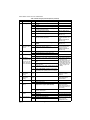
Table 4 provides the setup codes (IS codes) and values.
To enter the setup parameters:
1. Press the System (Heat/Cool) button to cycle
through the IS codes, which display in the upper
right following the word Setup.
2. Press the Up or Down Arrow buttons to cycle
through the option values for the currently displayed
IS code. The values display in the center of the
screen.
3. After the desired value displays, press the System
button to store your value selection and display the
next IS code.
Fig. 24. Installer Setup (IS) mode screen.
System
Fan
M27586
Set to
RoomTemp
Heat On
Heat
Auto
Fan On
ºF
ºF
UP AND DOWN
ARROW BUTTONS
SYSTEM
BUTTON
FAN
BUTTON
M27585
Setup
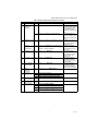
Table 4. Installer Setup (IS) Codes and Options.
IS
Code Code Description
Option
Value
Option Description (Default value shown in
Bold) Notes
1 Line Voltage
Selection
0 120 Vac power supply (Default)
1 240 Vac power supply
2 277 Vac power supply

TB6575/TB8575 DIGITAL FAN COIL THERMOSTATS
62-0311—13 12
2 System Type 0 Heat only
1 Cool only
2 Two pipes: Heat or Cool; Manual Changeover
3 Two pipes: Heat or Cool; Seasonal Changeover
(requires optional pipe sensor)
4 Four pipes: Manual Changeover TB6575A,TB6575B and
TB6575C only
5 Four pipes: Auto Changeover TB6575A,TB6575B and
TB6575C only
6 Two pipes: Heat or Cool; with Auxiliary Heat
(requires optional pipe sensor).
Allows auxiliary heat to turn
on when pipes have cold
water
(TB6575A,TB6575B and
TB6575C only).
7 Four pipes: Manual and Auto Changeover
(Default)
TB6575A,TB6575B and
TB6575C only
2.5 Fan On/Off
Selection for Aux
Heat On
0 Fan ON when Auxiliary Heat is on (Default) Enables or disables the
auto fan operation when
Auxiliary Heat is On
(TB6575A,TB6575B and
TB6575C only).
1 Fan OFF when Auxiliary Heat is on
3 Valve Output Type 0 Valve energized on call for heat or cool (Default)
1 Valve de-energized on call for heat or cool
4 Space Sensor Type 0 Onboard Sensor (Default)
1 Remote Sensor (TR21 or other 20K Ohm sensor)
5 Pipe Sensor
Only displays when
value 3 or 6 for the
System Type in IS
code #2 is selected.
0 Contact Open = Cool mode; Contact Closed = Heat
mode
• Pipe sensor will flash on
display screen if analog
input (#4) is lost.
• Pipe sensor status and
water temperature can
be checked in test mode
(see “Installer Test (IT)
Mode” on page 14 for
details)
1 Contact Open = Heat mode; Contact Closed = Cool
mode
2 Contact Open = Heat mode; Contact Closed = Cool
mode (same as 1)
3 Contact Open = Cool mode; Contact Closed = Heat
mode (same as 0)
4 Analog input (Default). NTC20K, whose curve is
the same as TR21.
Only displays when system type 3 or 6 is selected.
6 Pipe Sensor
Threshold for
Cooling
50 to
72
Range is 50°F to 72°F. Default is 60°F. Changes to Cool when pipe
temperature is below
threshold.
7 Pipe Sensor
Threshold for
Heating
75 to
90
Range is 75°F to 90°F. Default is 80°F. Changes to Heat when pipe
sensor temperature is
above threshold.
8 Temperature Scale 0 Degrees Fahrenheit (°F); Default.
1 Degrees Celsius (°C).
8.5 Fan Speed at motor
start up
0 Provide full power when fan motor starts –
always starts in high fan speed (Default)
High speed start up
ensures that there is
enough torque to start the
motor and eliminates and
motor locking.
1 Disable – fan will start at speed that is needed as
defined by VersaSpeed
9 Number of Fan
Speeds
1 Single Speed Fan Low speed only
2 2 Speed Fan Hi and Low speed fans only
3 3 Speed Fan (Default) Hi, Med, and Low speed fan
9.5 Fan Control Type 0 Constant and Auto (Default) When fan is in Auto, the fan
ramping algorithm,
VersaSpeed, is used
1 Auto only
Table 4. Installer Setup (IS) Codes and Options. (Continued)
IS
Code Code Description
Option
Value
Option Description (Default value shown in
Bold) Notes

TB6575/TB8575 DIGITAL FAN COIL THERMOSTATS
13 62-0311—13
10 Control Method for
4-Pipe Auto
Changeover
1 Single Setpoint (Default) Uses switching differential
to change between heating
and cooling and controls to
a single setpoint (Only
displayed for system types
5 or 7)
2 Heat and Cool Setpoints (2 setpoint method) Uses a deadband of no
control and controls to a
heat or cool setpoint. (Only
displayed for system types
5 or 7)
10.5 Deadband for Heat/
Cool Setpoints
2 to 9 Range is 2 to 9. Default is 3. Deadband = minimum
distance between heating and cooling setpoints.
Available when Heat and
Cool Setpoints are chosen
for the control method for 4-
pipe Auto (IS 10)
Switching
Differential for
Single Setpoint
2 to 6 Range is 2 to 6. Default is 3. Heat switching point =
setpoint - switching differential. Cool switching point
= setpoint + switching differential.
Available when Single
Setpoint is chosen for the
control method for 4-pipe
Auto (IS 10)
11 CPH Value for Heat 1 to 12 Range is 1 to 12. Default is 4. The number selected
indicates the maximum
times Heating is cycled on
per hour (CPH). IS 2
selection is 5.
12 CPH Value for Cool 1 to 6 Range is 1 to 6. Default is 3. The number selected
indicates the maximum
times Cooling is cycled on
per hour (CPH).
13 CPH for Auxiliary
Electrical Heater
1 to 12 Range is 1 to 12. Default is 6. The number selected
indicates the maximum
times Auxiliary Heating is
cycled on per hour (CPH).
14 Display
Temperature
Adjustment
-4 to 4 Range is -4°F to +4°F; Default is 0°F.
15 Temperature
Display Mode
0 Display Room Temperature
1 Display Setpoint
2 Display Temperature and Setpoint; Default.
16 Setpoint Range
Stop for Heating
50 to
90
Range is 50°F to 90°F. Default is 90°F.
17 Setpoint Range
Stop for Cooling
50 to
90
Range is 50°F to 90°F. Default is 50°F.
18 Keypad Lockout 0 All keys are available (Default)
1 The System button (Heat/Cool) is locked out
2 Both the System and Fan buttons are locked out.
3 All buttons are locked out (System, Fan, Up Arrow,
and Down Arrow). The LCD displays LOCKED.
Table 4. Installer Setup (IS) Codes and Options. (Continued)
IS
Code Code Description
Option
Value
Option Description (Default value shown in
Bold) Notes

TB6575/TB8575 DIGITAL FAN COIL THERMOSTATS
62-0311—13 14
Installer Test (IT) Mode
To enter Installer Test Mode:
• Press and hold both the Up arrow button and the
Down Arrow button for three (3) seconds.
This displays all segments of the LCD screen on the LCD.
See Fig. 22 on page 10.
Table 5 provides the Test codes (IT codes) and values. To
enter the IT codes:
1. Press the System (Heat/Cool) button to cycle
through the IT codes, which display in the upper
right above the word Test.
2. Press the Up or Down Arrow buttons to cycle
through the values for the currently displayed IT
code. The values display in the center of the screen.
19 Remote Setback 0 Disabled
1 Hotel card enabled N.O. for unoccupied mode with
1 second software delay going from UnOccupied to
Occupied;
2 minute delay going from Occupied to UnOccupied.
2 Hotel Card enabled N.C. for unoccupied mode with
1 second software delay going from UnOccupied to
Occupied;
2 minute delay going from Occupied to UnOccupied.
3 Hotel Card enabled N.O. for unoccupied mode with
1 second software delay going from UnOccupied to
Occupied;
30 minute delay going from Occupied to
UnOccupied
4 Hotel Card enabled N.C. for unoccupied mode with
1 second software delay going from UnOccupied to
Occupied;
30 minute delay going from Occupied to
UnOccupied.
5 Button Press (Default) Press and hold “Heat/Cool/
Off” button for 3 seconds
and thermostat will go into
“Economy Setback”
20 Remote Setback for
Heating
50 to
70
Range is 50°F to 70°F. Default is 64°F. Used when the thermostat
is in the Unoccupied state.
21 Remote Setback for
Cooling
72 to
90
Range is 72°F to 90°F. Default is 79°F.
22 Activity Sensing 0 Disabled (Default) This will be selectable when
IS 19 is set to option 0 or 5.
If IS 19 is configured for
N.O or N.C, activity sensing
will not be available.
1 4 hour sensing
2 8 hour sensing
3 12 hour sensing
4 16 hour sensing
5 20 hour sensing
6 24 hour sensing
23 Freeze Protection 0 Disabled This feature can not
activate when the
application is Cool only.
This function only occurs
when System switch is set
to OFF.
1 Enabled (Default) – Stat cycles On Heat when
room temperature reaches 40°F (4°C), and disables
Heat when room temperature reaches below 46°F
(8°C). The LCD displays FREEZE PROTECT
24 Auto Fan Reset 0 Inactive (Default) Auto Fan Reset is not
allowed (does not display)
when the fan control type is
set to Auto Only, (IS code
#9 - value 1).
1 Resets back to Auto after 2 hours. The start time is
calculated after the initial call for Heat/Cool is
satisfied. Then, the two (2) hour timing begins.
2 Resets back to Auto after 4 hours. The start time is
calculated after the initial call for Heat/Cool is
satisfied. Then, the four (4) hour timing begins.
25 Purge Cycle
Frequency
0 No periodic purge (other purges still apply) Option 1 Default is normally
recommended to make sure
changeover is detected
quickly on spring and fall
days.
1 Purge every 2 hours (Default)
2 Purge every 24 hours
Table 4. Installer Setup (IS) Codes and Options. (Continued)
IS
Code Code Description
Option
Value
Option Description (Default value shown in
Bold) Notes

TB6575/TB8575 DIGITAL FAN COIL THERMOSTATS
15 62-0311—13
3. After the desired value displays, press the System
button to store your value selection and display the
next IT code.
NOTE: Exiting Installer Test Mode is the same as the
method for entering test mode,
Fig. 25. Installer Test (IT) mode screen.
OPERATION
PROPORTIONAL + INTEGRAL
(P+I) CONTROL
Like a mechanical thermostat, the fan coil thermostats
have On/Off control output. However, this output is
regulated by a P+I algorithm, enabling the thermostat to
control closer to setpoint than conventional thermostats.
This results in performance where the space temperature
is maintained within 0.75°C (1.5°F) of the setpoint
regardless of fan speed.
NOTE: Integral action corrects the temperature con-
trol errors of proportional-only control, but it
is slower to react to large temperature or set-
point changes.
Economy Setback Modes
ACTIVITY SENSING (IS CODE #22)
If Activity Sensing is enabled, any time the thermostat is
not touched (no single key is pressed) for the duration
selected, the thermostat automatically falls back into the
Economy Setback. The LCD displays ECONOMY
SETBACK just to the right of the main temperature display
to indicate Activity Sensing mode is active. When any key
is pressed, the thermostat controls to Occupied mode.
BUTTON PRESS SETBACK (IS CODE #19-5)
The default remote setback option is for economy setback
via a button press on the thermostat. In this mode, the
thermostat can quickly be setback by pressing and
holding down the System Mode button for more than 3
seconds. The LCD displays ECONOMY SETBACK just to
the right of the main temperature display to indicate the
Setback is active. When any key is pressed, the
thermostat controls to Occupied mode.
REMOTE SETBACK (IS CODE #19)
Remote Setback is activated by a dry contact closure on
the remote setback input from an occupancy sensor, time
switch, or hotel card key. The thermostat controls to the
user/installer defined setback setpoints for increased
energy savings. The LCD displays Economy Setback just
to the right of the main temperature display to indicate the
Remote Setback mode is active.
When Remote Setback is active, all buttons on the
thermostat are disabled. However, the button
combinations to access Installer Setup (IS) and Installer
Test (IT) remain enabled.
ECONOMY SETBACK OPERATION
For Heat Mode, when Economy Setback is enabled, the
set point changes to the remote setback heating setpoint
(IS CODE #20).
For Cool Mode, when Economy Setback is enabled, the
set point changes to the remote setback cooling setpoint
(IS CODE #21).
For 4 pipe applications with Auto Changeover and Heat/
Cool Setpoints, when Economy Setback is enabled, the
cool setpoint changes to the remote setback cooling
setpoint and the heat setpoint changes to the remote
setback heating setpoint. The new effective deadband is
the difference between the remote setback heating
setpoint and the remote setback cooling setpoint.
Fig. 26 illustrates the relationship between setpoints,
Remote Setback, and deadband for auto changeover with
heat and cool setpoints.
Table 5. Installer Test (IT) Codes and Options.
IT
Code
Code
Description
Option
Value Option Description
10 Heat Control 0 Close
1 Open
20 Auxiliary Heat
Control
0Close
1 Open
30 Cool Control 0 Close
1 Open
40 Fan Control 0 Close
1 Low Speed
2 Medium Speed
3 High Speed
50 Pipe Sensor 32-199 Displays the pipe
sensor temperature.
Only used for System
Type 3 or 6 (IS code
#2, value 3 or 6). Only
the Analog pipe sensor
is tested.
71 Software Main
version
01-99 A 2-digit number, 01-99
72 Software Vice
version
01-99 A 2-digit number, 01-99
73 Configuration
Data Main version
01-99 A 2-digit number, 01-99
74 Configuration
Data Vice version
01-99 A 2-digit number, 01-99
75 Week Produced 01-52 A 2-digit number, 01-52
76 Year Produced 08-99 A 2-digit number, 08-99
M27587
Test

TB6575/TB8575 DIGITAL FAN COIL THERMOSTATS
62-0311—13 16
Fig. 26. Auto Changeover with Heat/Cool Setpoints
deadband illustration.
For 4 pipe applications with Auto Changeover and a single
setpoint, when Economy Setback is enabled, the setpoint
will revert to a dual heat/cool setpoint approach. The
remote setback heating and remote setback cooling
setpoints will be used to create an effective unoccupied
deadband.
Fig. 27 illustrates the unoccupied deadband when
Economy Setback is enabled for 4-pipe single setpoint
auto changeover.
Fig. 27. 4 Pipe Auto Changeover with Single Setpoint
and Economy Setback Deadband Illustration
Fan Modes
VERSASPEED™ FAN RAMPING
When the fan switch is in auto, the thermostat will cycle
the fan using the fan ramping algorithm. The appropriate
fan speed is selected according to Fig. 28.
The fan ramping algorithm is illustrated in Fig. 28
Fig. 28. VersaSpeed™ fan ramping algorithm
illustration.
AUTO FAN RESET (IS CODE #24)
If Auto Fan Reset is enabled, and a constant fan speed is
selected, the thermostat resets the fan to Auto.
• Value = 1: The fan resets back to Auto after 2 hours.
• Value = 2: The fan resets back to Auto after 4 hours.
The start time is calculated after the initial call for Heat/
Cool is satisfied. Then, the two or four hour timing begins.
The fan is set back to Auto when the 2-hour or 4-hour
delay expires.
Application Modes
2 PIPE SEASONAL CHANGEOVER APPLICATIONS
These applications require the pipe sensor as a N.O,
N.C., or Analog Input to detect seasonal changeover:
• 2 pipes with auto changeover
• 2 pipes with auxiliary heat
Changeover occurs when the system has been changed
over from the boiler to the chiller. This occurs on a
seasonal basis from winter to summer months. When
using a pipe sensor as an analog input, the thermostat
can use the logic below to determine what mode to
operate in. A changeover will occur when the pipe
temperature goes above the threshold for heating or
below the threshold for cooling. If a purge has not
occurred or a call has not been satisfied in awhile, the
pipe temperature may start to get close to the ambient
temperature. In this case, the thermostat will only
changeover once the temperature falls into the opposite
threshold.
2 Pipes with Auto Changeover
For this application the system switch only provides “Off”
and “Auto.” When in “Auto” mode the water temperature
will indicate if the thermostat should operate in heating or
cooling.
Operation:
After exiting the installer setup, the thermostat will perform
a 5 minute purge. During this initial 5 minute purge, the
valve (W/Y) will energize and the fan will be de-energized.
After the 5 minute purge, the thermostat will go into the
appropriate mode as described in Table 6.
Table 6. Logic for 2 Pipes with Auto Changeover
*If pipe temperature is between the two threshold values
after the 5 minute purge occurs, the thermostat will
activate a second 5 minute purge to double check the
water temperature. If after the second 5 minute purge, the
water temperature is still between the two thresholds, the
valve output will be disabled and only manual fan will be
available. It will stay in this operation until the next purge
cycle occurs.
2 Pipes with Auxiliary Heat
For this application, when there is hot water in the pipes,
the system switch provides “Off” and “Heat.” When there
is cold water in the pipes, the system switch provides
"Off," "Heat," and "Cool."
Operation:
After exiting the installer setup, the thermostat will perform
a 5 minute purge. During this time, the valve (W/Y) will
energize and the fan and auxiliary heat (Y/A) will be de-
energized. After the 5 minute purge, the thermostat will go
into the appropriate mode as described by Table 7.
UNOCCUPIED DEADBAND
DEADBAND
REMOTE SETBACK COOL SETPOINT
UNOCCUPIED DEADBAND
COOL SETPOINT
HEAT SETPOINT
REMOTE SETBACK HEAT SETPOINT
M27562
M31331
HEAT SWITCHING POINT
REMOTE SETBACK HEAT SETPOINT
REMOTE SETBACK COOL SETPOINT
COOL SWITCHING POINT
SETPOINT
UNOCCUPIED DEADBAND
UNOCCUPIED DEADBAND
-2°F
+2°F
+4°F
-4°F
FAN SPEED IS HIGH
DIFFERENCE
BETWEEN
RT AND
SETPOINT
COOL
HEAT
SETPOINT
M27563
FAN SPEED IS MEDIUM
FAN SPEED IS LOW
FAN SPEED IS HIGH
FAN SPEED IS LOW
FAN SPEED IS MEDIUM
Pipe Temperature after purge System Mode
>Threshold for Heating (IS code 7) Heat
Between Thresholds
After Purge Occurs
Fan Only*
< Threshold for Cooling (IS code 6) Cool

TB6575/TB8575 DIGITAL FAN COIL THERMOSTATS
17 62-0311—13
Table 7. Logic for 2 Pipes with Auxiliary Heat
If pipe temperature is between the two threshold values
after the 5 minute purge occurs, the thermostat will
activate a second 5 minute purge to double check the
water temperature. If after the second 5 minute purge, the
water temperature is still between the two thresholds, the
valve output will be disabled and only auxiliary heat will be
available for heating.
Auxiliary heat (Y/A) always de-energizes during purges.
Purge Cycles for 2 Pipe Seasonal Changeover
Applications
For 2 Pipe with Auto Changeover and 2 Pipe with
Auxiliary Heat applications, the thermostat will run purge
cycles to determine if there is hot or cold water in the
pipes.
A 5 minute purge will occur every 2 or 24 hours (IS 25) to
ensure that the pipe sensor is sensing the correct mode
during seasonal changeover months.
A 5 minute purge will also occur anytime the installer
setup or installer test menus are exited, whenever the
thermostat is switched from its “Off” position, and if the
power is reset.
NOTE: For the 2 Pipe with Auxiliary Heat application,
the thermostat must be in the “Off” position
for more than 30 minutes before a 5 minute
purge will occur when it is switched back into
“Heat” or “Cool.”
4 PIPES AUTO CHANGEOVER
Single Set Point Method
In 4 pipe auto changeover with a single setpoint, the
temperature is always controlled to the setpoint. Switching
points are used to determine when to switch between
heating and cooling modes. If the current mode is heat
and the temperature drifts above the cool switch point
(Setpoint + Switching Differential), the thermostat will
switch to heat operation and will heat the space until
setpoint is reached.
For this application, the setpoint setting and switching
points are illustrated in Fig. 29. The switching differential
is defined via IS code 10.
Fig. 29. 4 Pipe Auto Changeover with Single Setpoint
and Switching Points
Heat/Cool Setpoint Method
In 4 pipe auto changeover with heat and cool setpoints,
the system key is used to switch between the heating
setpoint and cooling setpoints. Use the Up and Down
arrow buttons to change the setpoint.
For this application, the setpoint settings and deadband
are illustrated in Fig. 30. The deadband is changed via IS
code 10.
Fig. 30. 4 Pipe Auto Changeover setpoints and
deadband.
Pipe
Temperature
After Purge Heat Mode Cool Mode
> Threshold
for Heating
(IS code 7)
Valve (W/Y)
energized on calls
for heat
Changeover.
Mode changes to
Heat.
Between
Thresholds
After Purge
Occurs
Aux Heat (Y/A)
energized on calls
for heat
Changeover. Mode
changes to Heat
because Cool is not
available.
< Threshold
for Cooling
(IS code 6)
Mode stays in Heat
but Aux Heat (Y/A)
energized on calls
for heat
Valve (W/Y)
energized on calls
for cool
M31330
HEAT SWITCHING POINT
COOL SWITCHING POINT
SWITCHING
DIFFERENTIAL
SETPOINT
DEADBAND
COOLING SETPOINT
HEATING SETPOINT
M27565

TB6575/TB8575 DIGITAL FAN COIL THERMOSTATS
62-0311—13 18
TROUBLESHOOTING
Table 8 provides troubleshooting information.
Table 8. Troubleshooting.
Symptom Possible Cause Action
Display does not
come on.
Thermostat is not being
powered.
For TB6575A/B/C, check for 120/240/277 Vac between L and N.
For TB8575A, check for 24 Vac between R and C.
Temperature settings
do not change.
The upper or lower
temperature limits were
reached.
Check the temperature setpoints for heating and cooling (Installer
Setup codes 16 and 17 respectively). Modify as needed.
The keypad is fully locked. Change keypad locked options (Installer Setup code #18).
Heating or cooling
does not come on.
System Type selection not
set to Heat or Cool or the
selection is incorrect.
Set the Installer Setup code #2 (System Type) to the correct value
to match the installed heating and/or cooling equipment. Verify
operation of wiring and equipment in Installer Test mode.
Thermostat is calling
for Heat (Heat on) or
Cool (Cool on) but no
heating or cooling is
running.
Heating or cooling
equipment is not
operating.
Check wiring. Check that the Installer Setup code #2 (System
Type) value matches the installed heating and/or cooling
equipment. Verify operation of equipment in Installer Test mode.
Heat does not turn on
(Heat On is solid in
the display).
Heating equipment failure. For TB6575A/B/C:
1. Check for 120/240/277 Vac at the equipment between power
and common, (terminals L and N).
2. Check for 120/240/277 Vac between the heat (W) and com-
mon (N) terminals. If 120/240/277 Vac is present, the ther-
mostat is functional.
For TB8575A:
1. Check for 24 Vac at the equipment on the secondary side of
the transformer between power and common (terminals R
and C).
2. Check for 24 Vac between the heat terminal (W) and trans-
former common. If 24 Vac is present, the thermostat is func-
tional.
If voltage is present, check the heating equipment to find the cause
of the problem.
Loose connection or
broken wire between
thermostat and heating
equipment.
For TB6575A/B/C:
Check for 120/240/277 Vac between the heat (W) and common
(N) terminals.
For TB8575A:
Check for 24 Vac between the heat terminal (W) and
transformer common.
If voltage is not present, check wire connection (loose or broken)
between the thermostat and the heating equipment.
Both the heating and
cooling equipment are
running at the same
time.
Incorrect System Type
selected.
Check that the Installer Setup code #2 (System Type) value
matches the installed heating and/or cooling equipment.
Heating and cooling wires
are shorted together.
Separate the shorted heating and cooling wires.

TB6575/TB8575 DIGITAL FAN COIL THERMOSTATS
19 62-0311—13
Cooling does not turn
on (Cool On is solid in
the display).
Cooling equipment failure. For TB6575A/B/C:
1. Check for 120/240/277 Vac at the equipment between power
and common, (terminals L and N).
2. Check for 120/240/277 Vac between the cool (Y) and com-
mon (N) terminals. If 120/240/277 Vac is present, the ther-
mostat is functional.
For TB875A:
1. Check for 24 Vac at the equipment on the secondary side of
the transformer between power and common (terminals R
and C).
2. Check for 24 Vac between the cool terminal (Y) and trans-
former common. If 24 Vac is present, the thermostat is func-
tional.
If voltage is present, check the cooling equipment to find the cause
of the problem.
Loose connection or
broken wire between
thermostat and cooling
equipment.
For TB6575A/B/C:
Check for 120/240/277 Vac between the cool (Y) and common
(N) terminals.
For TB875A:
Check for 24 Vac between the cool terminal (Y) and transformer
common.
If voltage is not present, check the wire connection (loose or
broken) between the thermostat and the cooling equipment.
Fan does not turn on
in a call for Heat.
Wiring or connection
failure
Check wiring and make sure the connection is correct.
Cannot select fan
speed.
Fan Control Type
selection is incorrect.
Check that the Installer Setup code #9 (Fan Control) value is set to
zero (0).
Heating equipment is
running in the Cool
mode.
Incorrect System Type
configured.
Check that the Installer Setup code #2 (System Type) value
matches the installed heating and/or cooling equipment.
Heating equipment
does not turn off and
heat temperature
setting is set below
room temperature
(Heat On is not in the
display).
Incorrect System Type
configured.
Check that the Installer Setup code #2 (System Type) value
matches the installed heating and/or cooling equipment.
Cannot set the system
setting to Heat.
System Type (Installer
Setup code #2) is set to
Cool Only (value = 1).
Set the Installer Setup code #2 value to match the installed heating
and/or cooling equipment.
Cannot set the system
setting to Cool.
System Type (Installer
Setup code #2) is set to
Heat Only (value = 0).
Set the Installer Setup code #2 value to match the installed heating
and/or cooling equipment.
Heat On is not in the
display.
System Type setting is not
set to Heat and/or the
temperature setting is not
set above the room
temperature.
Set the Installer Setup code #2 to Heat and set the temperature
setting above the room temperature.
Cool On is not in the
display.
System Type setting is not
set to Cool and/or the
temperature setting is not
set below the room
temperature.
Set the Installer Setup code #2 to Cool and set the temperature
setting below the room temperature.
Remote sensor does
not display
temperatures
Incorrect IS code. Set the Installer Setup code #4 to Remote (value = 1).
Sensor is not compatible. The remote sensor must be TR21 or compatible 20K NTC.
Remote Setback does
not activate
Incorrect IS code. Make sure the NO/NC and timer selection is correct. Check the
value selected for IS code 19.
Remote setpoint error. Make sure the remote setback setpoint is correct for energy saving
usage.
Table 8. Troubleshooting. (Continued)
Symptom Possible Cause Action

TB6575/TB8575 DIGITAL FAN COIL THERMOSTATS
Automation and Control Solutions
Honeywell International Inc.
1985 Douglas Drive North
Golden Valley, MN 55422
customer.honeywell.com
® U.S. Registered Trademark
© 2013 Honeywell International Inc.
62-0311—13 KK Rev. 10-13
Printed in United States
Activity Sensing does
not exit when button
pressed
All buttons are locked. Make sure keypad lockout is disabled. Set IS code 18, value = 0.
Freeze Protection
does not activate
System Type is set to
Cool.
Freeze protection is not activated when system type is Cool (IS
code 2; value = 1). Change System Type.
System mode is not Off. Set the System mode button to Off.
Auto Fan Reset does
not activate
Incorrect IS code. Set the Installer Setup code #24 to Enabled (value = 1 or 2).
Calling for Heat/Cool
setpoint couldn't be
satisfied.
Only after the setpoint is satisfied, will the auto fan reset timer
activate.
Table 8. Troubleshooting. (Continued)
Symptom Possible Cause Action
-
 1
1
-
 2
2
-
 3
3
-
 4
4
-
 5
5
-
 6
6
-
 7
7
-
 8
8
-
 9
9
-
 10
10
-
 11
11
-
 12
12
-
 13
13
-
 14
14
-
 15
15
-
 16
16
-
 17
17
-
 18
18
-
 19
19
-
 20
20


Honeywell Thermostat TB6575 User manual
- Category
- Thermostats
- Type
- User manual
Ask a question and I''ll find the answer in the document
Finding information in a document is now easier with AI
Related papers
-
Honeywell TB6575 User manual
-
Honeywell SUITEPRO TB6575 Installation Instructions Manual
-
-
Honeywell T8621D User manual
-
-
-
-
-
-
Other documents
-
Johnson Controls T701DFN-1 Owner's manual
-
Robertshaw 300-204 Owner's manual
-
Venstar T1070 User manual
-
ClimateMaster ATA11C04 Install Manual
-
Carrier 42 SERIES User manual
-
-
Bradford White 47808A User manual
-
 Vtronix T201 Installation guide
-
-
Premier Mounts PSD-D User manual
