JVC SP-XCA75 User manual

Category
DVD players
Type
User manual

This manual is also suitable for

For Customer Use:
Enter below the Model No. and Serial
No. which are located either on the rear,
bottom or side of the cabinet. Retain this
information for future reference.
Model No.
Serial No.
LVT0958-010A
[A]
INSTRUCTIONS
DVD DIGITAL CINEMA SYSTEM
TH-A75
Consists of XV-THA75, SP-WA75, SP-XSA75, and SP-XCA75
STANDBY
COMPACT
SUPER VIDEO
DIGITAL•EX
PRO LOGIC
DVD DIGITAL CINEMA SYSTEM
PROGRESSIVE
PHONES
SOURCE
VOLUME +
RM–STHA75U
DVD CINEMA SYSTEM
CHANNEL/ZOOM
VOLUMETV VOL
TUNING
STOP
DIMMER
PAUSE
FF/
/REW
TV/VIDEO
1
MUTING
¡
REC
PLAY
DOWN UP
MEMORY
STROBE
DVD
VCR 1
AUDIO
VCR/DBS
ANGLE
FM/AM
SUBTITLE
DECODE
RETURN DIGEST
VFP
TOP MENU
MENU
CONTROL
EFFECT
S.WFR
TEST
SLEEP
TV
VCR
SETTING
TV RETURN
ENTER
ON
SCREEN
CHOICE
FM MODE
123
456
789
10
0
+10
100+
TV AUDIO
VCR
SOUND
AUDIO/
TV/VCR
CATV/DBS
PROGRESSIVE
SURROUND
OFF
DSP
CENTER
+
+
+
+
SURR-L
SURR-R
S-BACK
+
ADJUST
O.T.
REPLAY
XV-THA75
SP-XSA75
SP-WA75
SP-XCA75
cover.TH-A75[A]_f 02.10.17, 5:50 PM1
G-1
CAUTION
To reduce the risk of electrical shocks, fire, etc.:
1. Do not remove screws, covers or cabinet.
2. Do not expose this appliance to rain or moisture.
CAUTION
Do not block the ventilation openings or holes.
(If the ventilation openings or holes are blocked by a newspaper
or cloth, etc., the heat may not be able to get out.)
Do not place any naked flame sources, such as lighted
candles, on the apparatus.
When discarding batteries, environmental problems must be
considered and local rules or laws governing the disposal of
these batteries must be followed strictly.
Do not expose this apparatus to rain, moisture, dripping or
splashing and that no objects filled with liquids, such as
vases, shall be placed on the apparatus.
Warnings, Cautions and Others
Caution –– button!
Disconnect the mains plug to shut the power off completely.
The button in any position does not disconnect the mains line.
The power can be remote controlled.
Caution: Proper Ventilation
To avoid risk of electric shock and fire and to protect from damage,
locate the apparatus as follows:
Front: No obstructions open spacing.
Sides: No obstructions in 10 cm from the sides.
Top: No obstructions in 15 cm from the top.
Back: No obstructions in 20 cm from the back.
Bottom: No obstructions, place on the level surface.
In addition, maintain the best possible air circulation as illustrated.
Wall or
obstructions
Floor
Front
XV-THA75
Spacing 20 cm or more
Stand height 15 cm or more
safety.TH-A75[A]_f 02.10.17, 0:55 PM1
G-2
1. CLASS 1 LASER PRODUCT
2. CAUTION: Visible and invisible laser radiation
when open and interlock failed or defeated.
Avoid direct exposure to beam.
3. CAUTION: Do not open the top cover. There
are no user serviceable parts inside the unit;
leave all servicing to qualified service personnel.
IMPORTANT FOR LASER PRODUCTS
1 CLASSIFICATION LABEL, PLACED ON EXTERIOR
SURFACE
REPRODUCTION OF LABELS
2 WARNING LABEL, PLACED INSIDE THE UNIT
safety.TH-A75[A]_f 02.10.17, 0:55 PM2
1
Table of contents
Introduction ........................................... 2
About this manual ............................................................. 2
Precautions ........................................................................ 2
Checking the supplied accessories ................................. 2
Names of parts and controls .................. 3
Center unit .......................................................................... 3
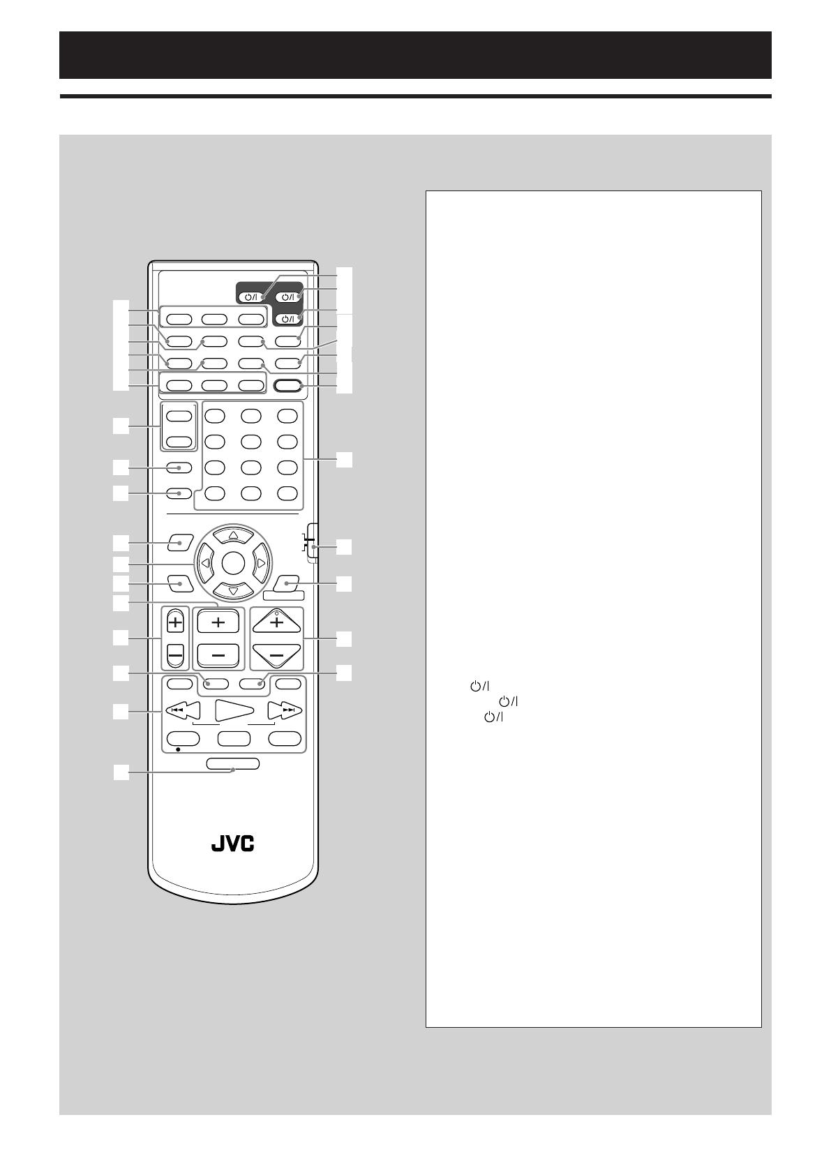
Remote control................................................................... 4
About discs ............................................ 5
Playable disc types ............................................................ 5
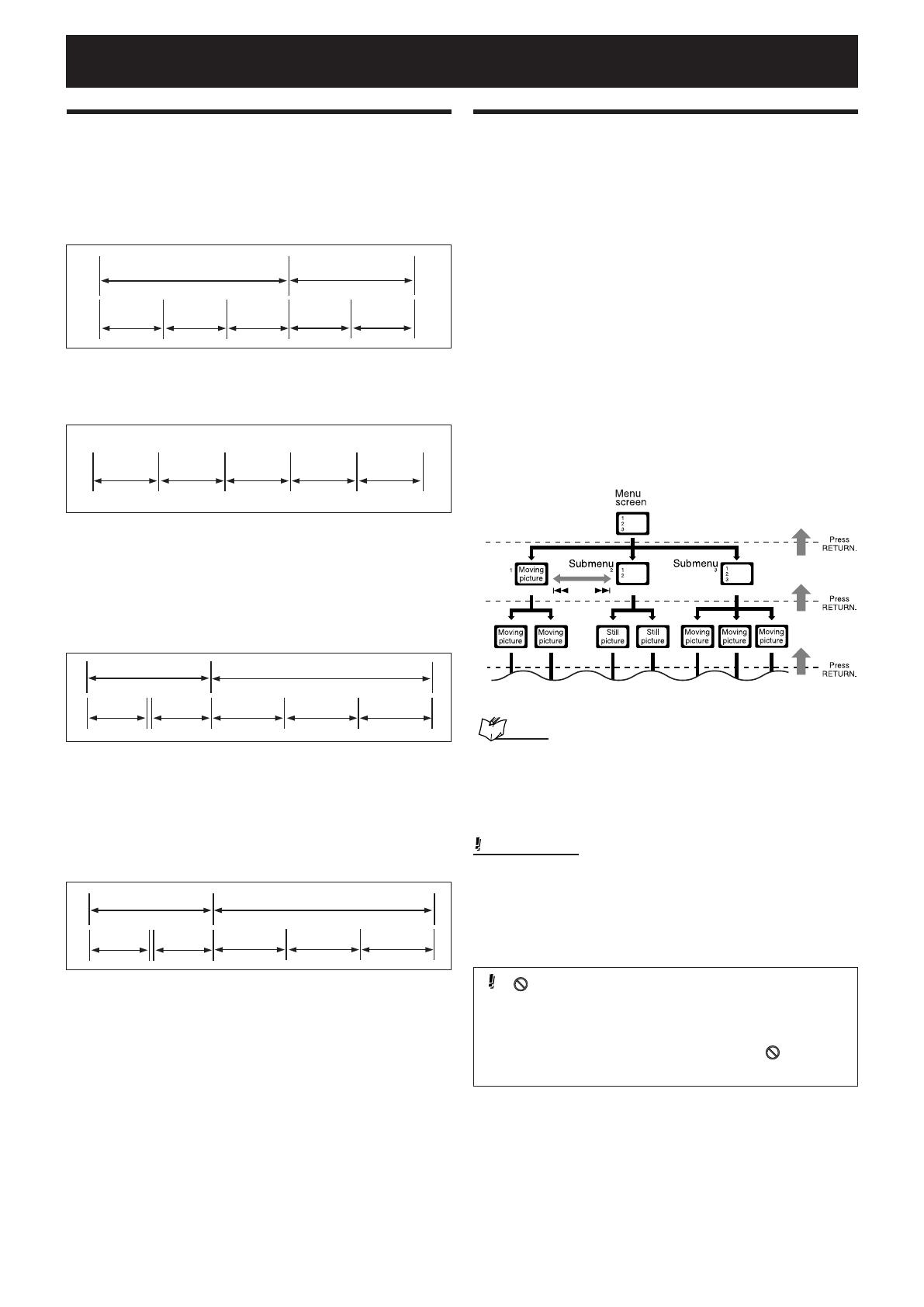
Disc structure ..................................................................... 6
Playback Control function (PBC)
—Only for VCD and SVCD ........................................... 6
Getting started ...................................... 7
Connections ....................................................................... 7
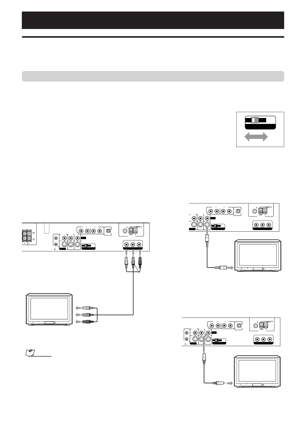
Connecting a TV ................................................................. 7
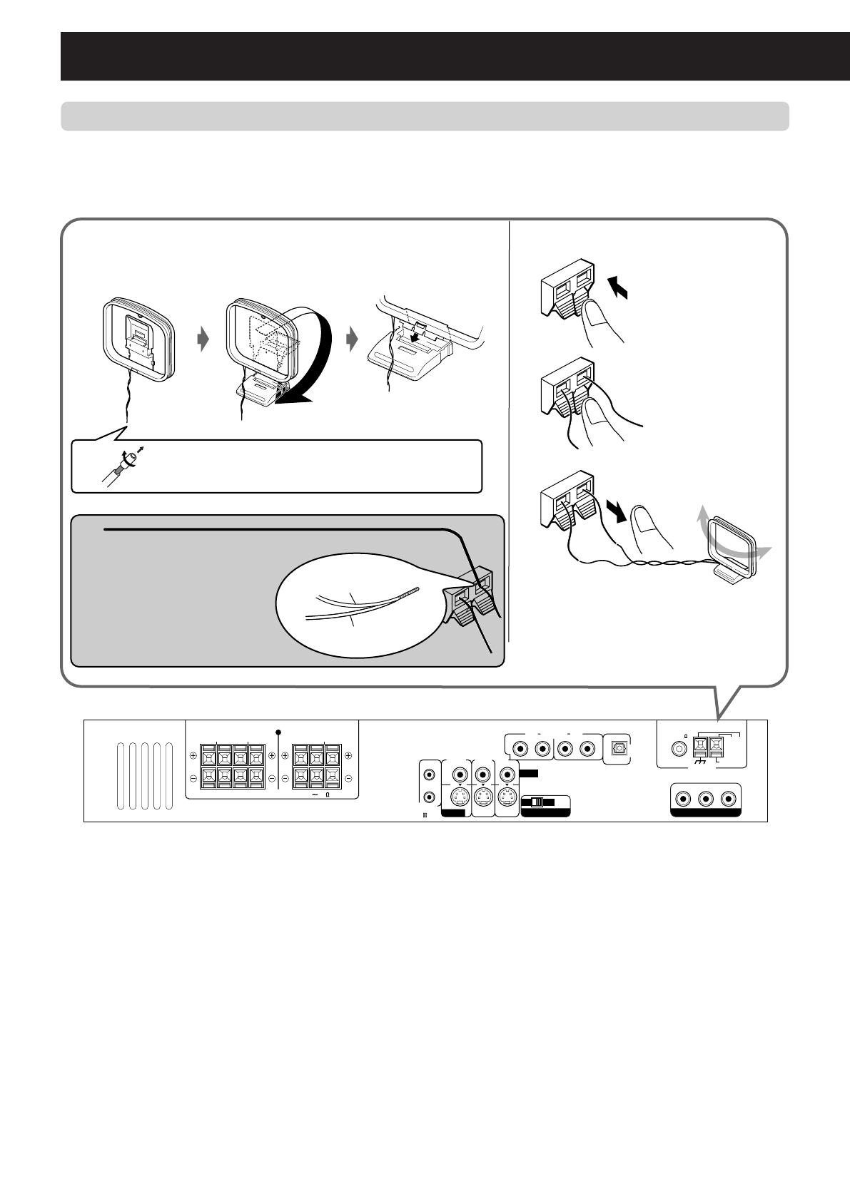
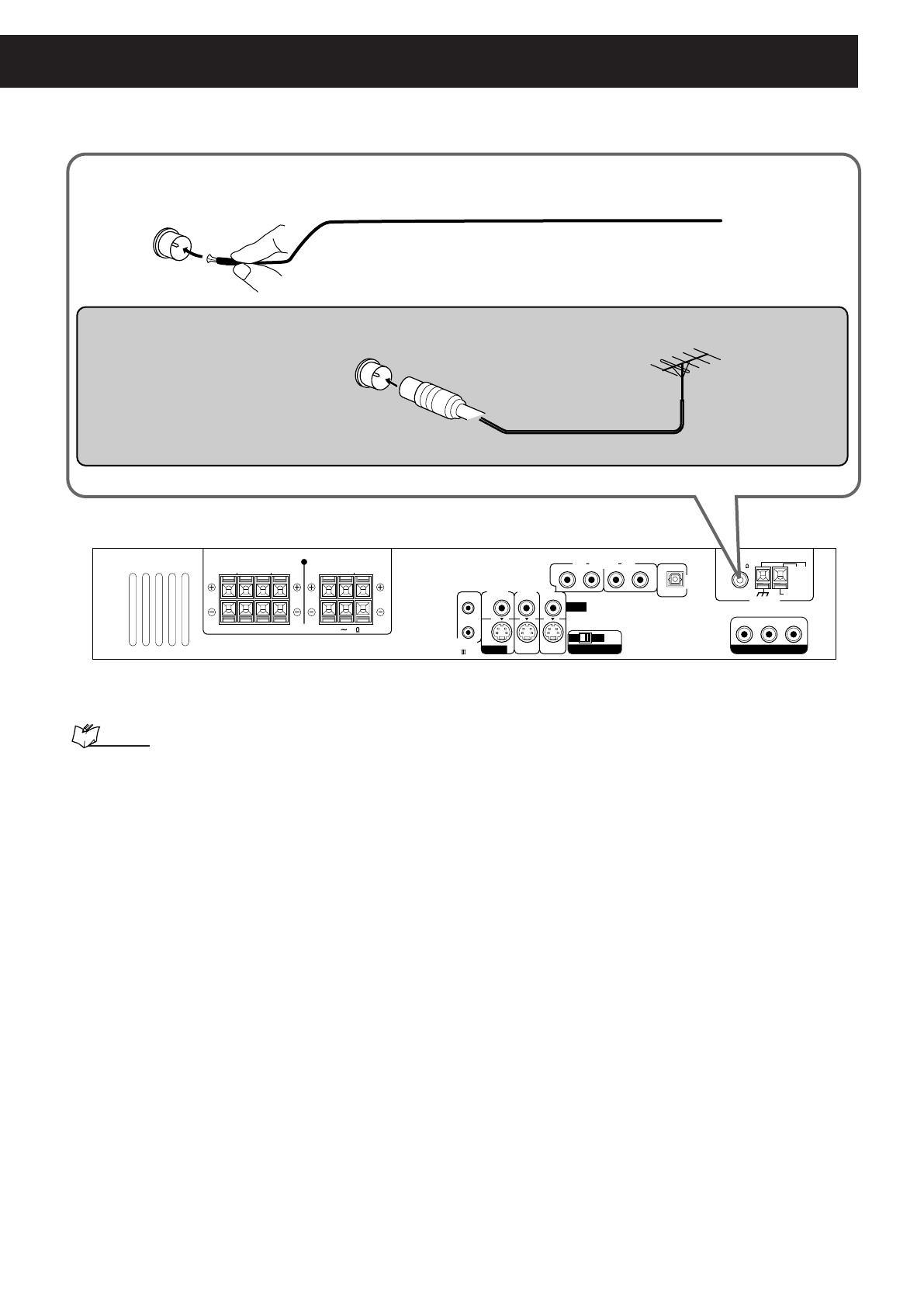
Connecting the AM and FM antennas ............................... 8
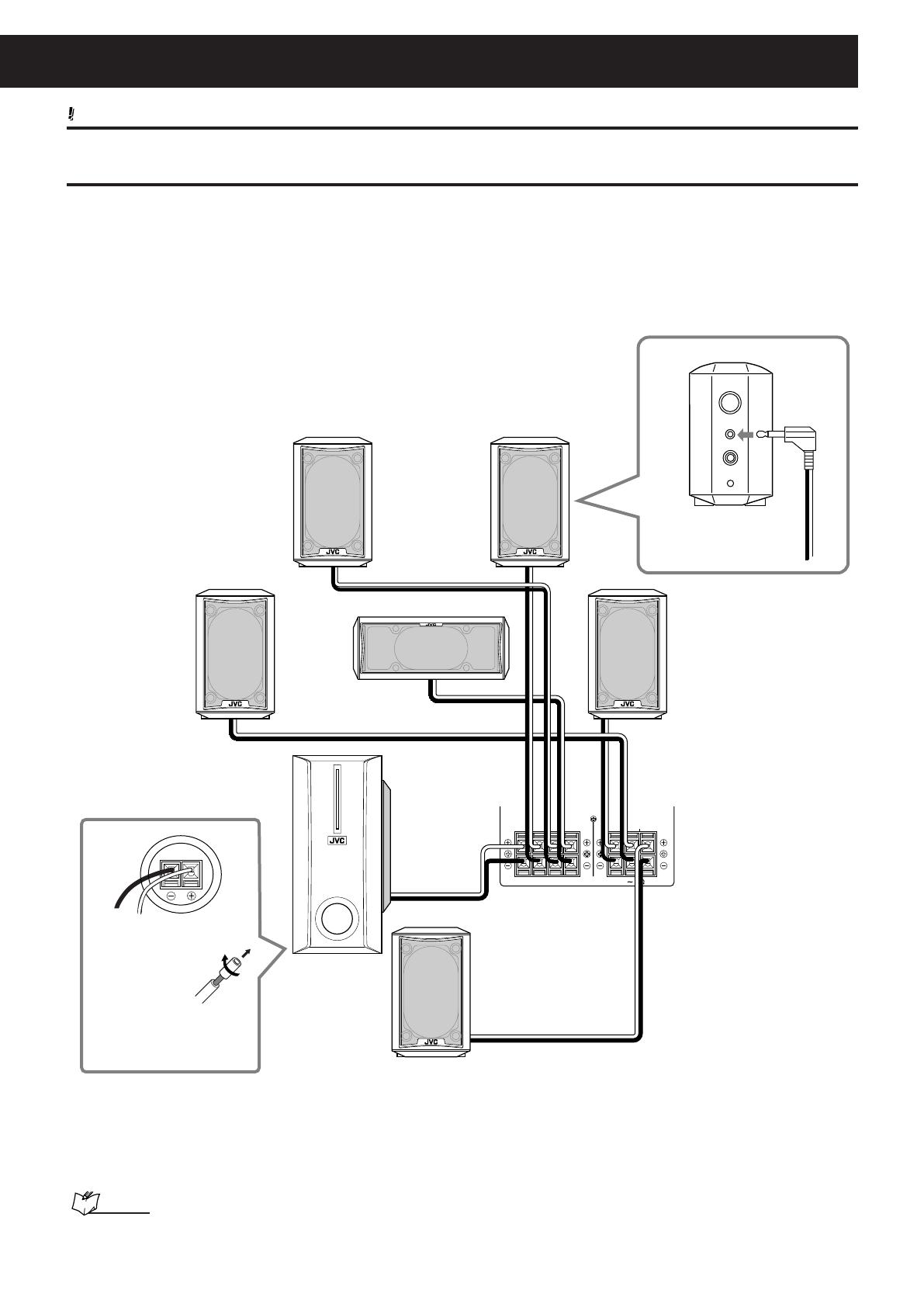
Connecting the satellite speakers and subwoofer ........... 10
Installing the satellite speakers on the wall ...................... 12
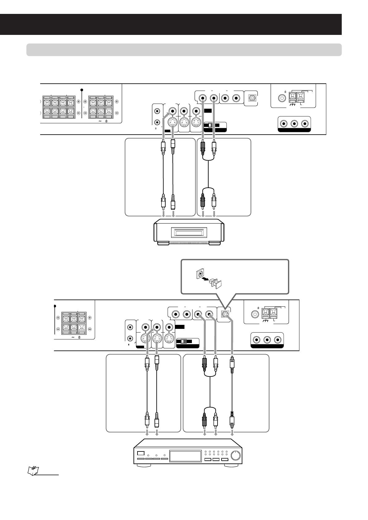
Connecting video components ........................................ 13
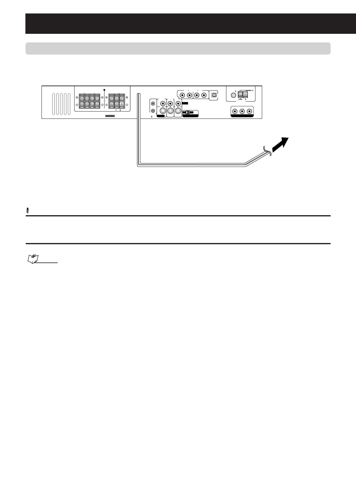
Connecting the power cord .............................................. 14
Using the remote control ................................................ 15
Putting batteries in the remote control .............................. 15
Operating the system using the remote control ............... 15
Basic operations .................................. 16
Turning on the system ..................................................... 16
Selecting the source to play ........................................... 16
Adjusting the volume ...................................................... 17
Adjusting the output level of subwoofer ....................... 17
Turning off the sound temporarily ................................. 17
Adjusting the brightness ................................................ 17
Turning off the power with the sleep timer .................... 18
Changing the analog/digital input mode and
decoding mode ........................................................... 18
Storing basic adjustments—auto memory .................... 19
Changing the scannig mode ........................................... 19
Basic DVD player operations ................ 20
Tuner operations .................................. 22
Setting the AM tuner interval spacing ........................... 22
Tuning in to stations manually ....................................... 22
Using preset tuning ......................................................... 22
Selecting the FM reception mode .................................. 23
Reducing the noise of AM broadcast............................. 23
Basic settings ....................................... 24
Operating procedure ....................................................... 24
Setting speaker sizes ...................................................... 24
Selecting the channel number to reproduce
multi-channel digital software .................................. 24
Setting the speaker distance .......................................... 25
Setting the crossover frequency .................................... 25
Setting the phase of subwoofer ..................................... 25
Setting the video output for DVD playback ................... 25
Audio adjustments ............................... 26
Operating procedure ....................................................... 26
Adjusting the tone ........................................................... 26
Setting the level of the low frequency effect attenuator ... 26
Setting the dynamic range .............................................. 26
Reinforcing the bass sound ............................................ 26
Setting the subwoofer audio position ............................ 26
Adjusting the front speakers balance ............................ 26
Creating realistic sound fields .............. 27
Surround modes .............................................................. 27
DSP modes ....................................................................... 29
Using Surround mode .................................................... 31
Using DSP Mode .............................................................. 31
Adjusting sound .............................................................. 32
DVD player operations ........................ 33
Using the on-screen bar .................................................. 33
Showing the on-screen bar .............................................. 33
Basic operation through the on-screen bar ...................... 34
Changing the time information ....................................... 34
Locating a particular scene from the disc menu .......... 35
Locating a particular scene from the DVD menu ............. 35
Locating a particular scene from
the VCD/SVCD menu with PBC .................................. 35
Selecting a view angle ..................................................... 36
Showing all view angles on the TV ................................... 36
Changing the subtitle and audio languages ................. 37
Selecting the subtitle language ........................................ 37
Selecting the audio language .......................................... 37
Selecting the audio channel ............................................. 38
Playing from a particular position .................................. 39
Locating a particular chapter––Chapter search .............. 39
Locating a particular position––Time search ................... 39
Locating a particular scene—DIGEST ............................. 40
Special picture playback ................................................. 41
Frame-by-frame playback ................................................ 41
Showing continuous still pictures ..................................... 41
Playing back in slow-motion ............................................. 42
Zooming in and out .......................................................... 42
Changing the VFP setting ................................................. 43
Playing back in the desired order—Program play ........ 44
Playing back in random order—Random play .............. 44
Repeat play ....................................................................... 45
Repeating title, chapter, or tracks .................................... 45
Repeating a particular portion—A-B repeat ..................... 45
MP3 disc playback .............................. 46
Basic operation ................................................................ 46
Operating through the MP3 CONTROL screen ............. 47
JPEG disc playback .............................. 48
Slide-show ........................................................................ 48
Operating through the JPEG CONTROL screen ........... 49
Using the choice menus........................ 50
Choice menus .................................................................. 50
Configuration of the choice menus .................................. 50
Operation buttons for the choice menus .......................... 50
Basic operating procedure ............................................... 51
LANGUAGE menu ............................................................ 52
PICTURE menu ................................................................ 53
AUDIO menu ..................................................................... 54
SPK. SETTING menu ....................................................... 55
OTHERS menu ................................................................ 56
Restricting playback—Parental Lock ............................. 57
Setting Parental Lock........................................................ 57
Changing the setting of Parental Lock ............................. 58
Releasing Parental Lock temporarily ................................ 58
AV COMPU LINK remote control system ... 60
Operating other manufacturers’
video equipment .............................. 62
Operating TV ..................................................................... 62
Operating CATV converter or DBS tuner ....................... 63
Operating VCR.................................................................. 64
Maintenance ........................................ 65
Troubleshooting ................................... 66
Glossary .............................................. 69
Specifications ....................................... 70
EN01-15.TH-A75[A]_f 02.10.11, 2:51 PM1
2
About this manual
This manual mainly explains operations using the buttons and
controls on the remote control. You can also use the buttons
on the center unit if they have the same or similar names (or
marks) as those on the remote control.
If operation using the remote control is different from that
using the center unit, then it is explained.
Times given for various operations are for reference only.
Actual time will vary somewhat.
The following marks are used in this manual:
:Special warnings and cautions you need
to know to obtain the best possible
performance from the system.
:Specific information and hints you need
to know about the features and
procedures.
:Available disc types for the operations
explained in each section. Unavailable
disc types are shown in halftone color.
Precautions
Installation of the system
Select a place which is level, dry and neither too hot nor
too cold—between 5°C and 35°C.
Leave sufficient distance between the system and the TV.
Do not use the system in a place subject to vibration.
Power cord
Do not handle the power cord with wet hands.
A small amount of power (2.5 watts) is always consumed
while the power cord is connected to the wall outlet.
When unplugging the power cord from the wall outlet,
always pull the plug, not the power cord.
To prevent malfunction of the system
There are no user-serviceable parts inside. If anything goes
wrong, unplug the power cord and consult your dealer.
Do not insert any metallic object into the system.
Do not use any of the nonstandard shaped discs (like a
heart, flower, or credit card, etc.) available on the market.
Do not use a disc with tape, stickers, or paste on it.
About copyright laws
Check the copyright laws in your country before recording
from DVD Video (DVD), Super Video CD (SVCD), Video CD
(VCD), and Audio CD discs. Recording of copyrighted
material may infringe copyright laws.
About the copyguard system
The DVD Video discs are copy-protected. If you connect a
VCR between this system and your TV, the copyguard system
is activated and the picture may not be played back
correctly.
Introduction
Sticker
Paste
Label sticker
7 Safety precautions
Avoid moisture, water and dust
Do not place the system in moist or dusty places.
Avoid high temperatures
Do not expose the system to direct sunlight and do not place
it near a heating device.
When you are away
When away on a journey or otherwise, for an extended period
of time, remove the plug from the wall outlet.
Do not block the vents
Blocking the vents may damage the system.
Care of the cabinet
When cleaning the system, use a soft cloth and follow the
relevant instructions on the use of chemically-coated cloths.
Do not use benzine, thinner or other organic solvents
including disinfectants. These may cause deformation or
discoloring.
If water gets inside the system
Turn the system off and remove the plug from the wall outlet,
then call the store where you made your purchase.
Continuing use of the system in this state may cause a fire or
electrical shock.
Checking the supplied
accessories
Check to be sure you have all the supplied accessories.
The number in parentheses is the quantity of the pieces
supplied.
If anything is missing, contact your dealer immediately.
Center unit package
Remote control—RM-STHA75U (1)
Batteries—R6S (SUM-3)/AA (15F) (2)
FM antenna (1)
AM loop antenna (1)
Composite video cord (1)
AV COMPU LINK cord (1)
Core filter (1)
Speaker package
Speaker cords
Approx. 5 m (3) with a mini plug
:For the left front speaker, right front
speaker, and center speaker
Approx. 5 m (1) :For the subwoofer
Approx. 10 m (3) with a mini plug
:For the left surround speaker, right
surround speaker, and surround back
speaker
Satellite speakers wall brackets (5)
Screws for the satellite speakers wall brackets (5)
EN01-15.TH-A75[A]_f 02.11.5, 3:44 PM2
3
Names of parts and controls
See pages in the parentheses for details.
Center unit
Front panel
LINEAR PCM
L
S.WFR
LS
RS
C
R
S
LFE
DSP
SB
PRO LOGIC
DIGITAL EX
CH
MP3
RESUME
BASS
SURROUND
TUNED ST AUTO
MUTING
1
2
3
4 5
9
p
8
7
6
1
2
R
1 • LINEAR PCM indicator (18)
• Pro Logic indicators (28)
PRO LOGIC, PRO LOGIC II
• Digital signal format indicators (18, 27, 28)
DIGITAL, DIGITAL EX , DTS
2 MP3 indicator (46)
3 CH (channel) indicator (23)
4 Main display
1
4 5 6
7
8
9
p
q
w
t
2
3
e
r
STANDBY
COMPACT
SUPER VIDEO
DIGITALEX
PRO LOGIC
DVD DIGITAL CINEMA SYSTEM
PROGRESSIVE
PHONES
VOLUME +SOURCE
1 STANDBY lamp (16)
2
(standby/on) button (16)
3 Disc tray (20)
4 0 (open/close) button (20)
5 PROGRESSIVE lamp (19)
6 7 (stop) button (20, 22, 46, 48, 49)
7 3 (play) button (20, 46, 48, 49)
8 8 (pause) button (20, 22, 41, 46, 48)
9 4 (reverse skip) button (20, 46, 48)
p ¢ (forward skip) button
(20, 22, 46, 48)
5 RESUME indicator (21, 56)
6 Signal (1) and speaker (2) indicators (30)
7 SURROUND indicator (27, 28, 30, 31)
8 DSP indicator (29, 31)
9 Tuner operation indicators (22, 23)
TUNED, ST (stereo), AUTO MUTING
p BASS indicator (26)
q SOURCE button (16)
w VOLUME +/– buttons (17)
e Display (see below)
r Remote sensor (15)
t PHONES jack (17)
Display
Rear panel
VIDEO OUT SELECT
COMPONENT VIDEO OUT
SURROUND SPEAKERS SURROUND BACK
VCR
PAL
NTSC
DBS
COAXIAL
AM LOOP
(
DBS
)
RIGHT LEFT SPEAKER
VCR IN
AV COMPU
LINK-
S-VIDEO
DIGITAL IN
ANTENNA
DBS IN OUT
AUDIO IN
VIDEO
RL RL
CENTER
RIGHTSUBWOOFER LEFT SPEAKER
CAUTION:SPEAKER IMPEDANCE 4 16
FM 75
AM EXT
FRONT SPEAKERS
Y
P
B
P
R
1
3
4 5
6 7
8
2
9
1 Speaker terminals (11)
SUBWOOFER,
RIGHT/LEFT FRONT SPEAKERS,
CENTER SPEAKER,
RIGHT/LEFT SURROUND SPEAKERS,
SURROUND BACK SPEAKER
2 Power cord (14)
3 AUDIO IN jacks (13)
VCR, DBS
4 DIGITAL IN (DBS) terminal (13)
5 ANTENNA terminals (8, 9)
6 AV COMPU LINK-III jacks (60)
7 VIDEO jacks
VCR IN (13), DBS IN (13), OUT (7)
8 VIDEO OUT SELECT switch (7)
9 COMPONENT VIDEO OUT jacks
Y, P
B, PR (7)
EN01-15.TH-A75[A]_f 02.10.11, 2:51 PM3
4
Remote control
RM–STHA75U
DVD CINEMA SYSTEM
CHANNEL/ZOOM
VOLUMETV VOL
TUNING
STOP
DIMMER
PAUSE
FF/
/REW
TV/VIDEO
1
MUTING
¡
REC
PLAY
DOWN UP
MEMORY
STROBE
DVD
VCR 1
AUDIO
VCR/DBS
ANGLE
FM/AM
SUBTITLE
DECODE
RETURN DIGEST
VFP
TOP MENU
MENU
CONTROL
EFFECT
S.WFR
TEST
SLEEP
TV
VCR
SETTING
TV RETURN
ENTER
ON
SCREEN
CHOICE
FM MODE
123
456
789
10
0
+10
100+
TV AUDIO
VCR
SOUND
AUDIO/
TV/VCR
CATV/DBS
SURROUND
OFF
DSP
CENTER
+
+
+
+
SURR-L
SURR-R
S-BACK
+
ADJUST
O.T.
REPLAY
PROGRESSIVE
7
1
2
3
4
6
5
8
9
p
q
w
e
r
y
u
i
o
;
a
g
h
j
k
l
f
d
t
/
s
1 Source selecting buttons (16)
VCR/DBS, FM/AM, DVD
2 AUDIO button (37, 38)
3 ANGLE button (36)
4 TOP MENU button (35)
5 MENU button (35, 49)
6 Surround and DSP operation buttons
SURROUND (20, 31), DSP (20 31), OFF (31)
7 CONTROL buttons
VCR (64), TV (62, 63)
8 SLEEP button (18)
9 SETTING button (24)
ADJUST button (26)
p ON SCREEN button (33, 34)
q ENTER button (34, 47, 49)
Cursor 3/2//5 buttons (24, 26, 34, 46 – 49)
Choice menu operation buttons (50, 57, 58)
w CHOICE button (50, 57, 58)
e CHANNEL +/– buttons (62 – 64)
ZOOM +/– buttons (42, 49)
r TV VOL (volume) +/– buttons (62)
t TV/VIDEO button (62)
y Disc Operation buttons
(20, 35, 40 42, 46, 48, 49, 64)
1, ¡, 4/REW, PLAY, FF/¢,
O.T. (one touch) REPLAY, STOP, PAUSE
• TUNING UP/DOWN buttons (22)
÷ REC button (64)
• MEMORY button (23)
• STROBE button (41)
u DIMMER button (17)
i TV
button (62, 63)
o AUDIO
button (16)
; VCR
button (64)
a DECODE button (18)
s SUBTITLE button (37)
d DIGEST button (40)
f RETURN button (35)
g SOUND button (17, 32)
h Number buttons
(21, 23, 35, 39, 44, 47, 49, 57, 58, 62 64)
• Sound setting buttons (17, 32)
S.WFR +/–, CENTER +/–, SURR-L +/–,
S-BACK +/–, SURR-R +/–
• EFFECT button (32)
• TEST button (32)
• TV RETURN button (62)
• FM MODE button (23)
j Remote control mode selector (16, 63)
k • VFP button (43)
• PROGRESSIVE button (19)
l VOLUME +/– buttons (17)
/ MUTING button (17)
Names of parts and controls
EN01-15.TH-A75[A]_f 02.10.11, 2:51 PM4
5
54
2
3
4
5
4
About discs
Playable disc types
This system has been designed to play back the following
types of discs:
DVD Video (DVD), Video CD (VCD), Super Video CD
(SVCD), Audio CD, CD-R, and CD-RW
This system can also play back MP3 and JPEG files
recorded on CD-Rs and CD-RWs. For in-depth information
about MP3, see “MP3 disc playback” on page 46, and for
JPEG, see “JPEG disc playback” on page 48.
Finalized DVD-R discs recorded with the DVD VIDEO
format can be played back. However, some discs may not
be played back because of the disc characteristics or
recording conditions.
Discs you can play:
Disc Mark Video Region Code
Type (Logo) Format Number*
DVD Video
NTSC/PAL
4
(DVD) ALL
Video CD
NTSC/PAL ——
(VCD)
Super Video CD
NTSC/PAL ——
(SVCD)
Audio CD —— ——
CD-R —— ——
CD-RW —— ——
* Note on Region Code
DVD players and DVDs have their own Region Code
numbers. This system can play back only DVDs recorded
with the color system of NTSC or PAL whose Region Code
numbers include “4.”
Ex.:
If a DVD with the improper Region Code numbers is
loaded, “REGION CODE ERROR” appears on the display
and playback cannot start.
The following disc types cannot be played back:
DVD Audio, DVD-ROM, DVD-RAM, DVD-RW, DVD+RW,
CD-ROM, CD-I (CD-I Ready), Photo CD, etc.
Playing back these discs will generate noise and damage
the speakers.
COMPACT
DIGITAL AUDIO
On some DVD, VCD, or SVCD discs, the actual
operations may be different from what is explained in
this manual. This is due to the disc programming and
disc structure, and this is not a malfunction of this
system.
Notes on CD-R and CD-RW
User-edited CD-Rs (Recordable) and CD-RWs
(Rewritable) can be played back only if they are already
finalized.”
The system can play back CD-Rs or CD-RWs recorded on
a personal computer if they have been recorded in the
Audio CD format.
The system can also play back CD-Rs or CD-RWs if MP3
tracks (files) or JPEG files are recorded on them.
Note that the configuration and characteristics of an MP3
disc or a JPEG disc is determined by the writing
(encoding) software and hardware used for recording.
Therefore, due to the software and hardware used, the
following symptoms may occur:
Some discs may not be played back at all.
Some tracks (files) on an MP3 disc are skipped and
may not be played back normally.
Some files on a JPEG disc may be distorted during
playback.
Before playing back CD-Rs or CD-RWs, read their
instructions or cautions carefully.
CD-RWs may require a longer read-out time. This is
caused by the fact that the reflectance of CD-RWs is
lower than for regular CDs.
7 About MP3 discs
This system can play MP3 files recorded on a CD-R or
CD-RW. We call such a disc “MP3 disc” in this manual.
MP3 is an abbreviation of Motion Picture Experts Group 1 (or
MPEG-1) Audio Layer 3. MP3 is simply a file format with a
data compression. By using MP3 format, one CD-R or CD-
RW can contain 10 times as much data volume as a regular
CD can.
This system simplifies the hierarchical construction of a disc
and calls files and folders as “tracks” and “groups.”
7 About JPEG discs
This system can play JPEG files such as digital photographs
recorded on a CD-R or CD-RW. We call such a disc “JPEG
disc” in this manual.
JPEG is a still-picture data compression system proposed by
Joint Photographic Expert Group, which features small
decrease in image quality in spite of its high compression
ratio.
This system simplifies the hierarchical construction of a disc
and calls folders as “groups.”
EN01-15.TH-A75[A]_f 02.10.11, 2:51 PM5
6
Track 1
Track 2 Track 3
Track 4 Track 5
Disc structure
A DVD disc consists of “titles,” and each title may be divided
into some “chapters.”
For example, if a DVD disc contains some movies, each
movie may have its own title number, and it may be further
divided into chapters.
Playback Control function (PBC)
Only for VCD and SVCD
The Playback Control function allows you to enjoy menu-
driven operation and high-resolution still images with a
resolution four times greater than moving pictures.
High-resolution still image display
You can display high-quality images which are four times
clearer than moving pictures.
Menu-driven playback
A selection menu is displayed when you start playing a
VCD or SVCD disc with the Playback Control function. The
selection menu shows a list of numbers to pick from. Some
discs may show moving pictures or a divided screen.
You can interact with the screen using a menu display to
select and play an entry.
The illustration below shows the basic features of menu
driven playback. See page 35 for details about using the
menu.
NOTE:
While operating a VCD or SVCD using the menu, some of the
functions, such as repeat play, may not work.
IMPORTANT:
Before playing a disc, make sure of the following....
Check the connection with the TV.
Turn on the TV and select the correct input mode on the TV
to view the pictures or on-screen information on the TV
screen.
If appears on the TV screen when pressing a
button, the disc cannot accept an operation you have
tried to do, or information required for that operation is
not recorded on the disc.
NOTICE: In some cases, without showing ,
operations will not be accepted.
Group 2
Group 1
Group 3
Group 4 Group 5
Track 1
Track 2
Group 2
Group 1
Group 3
Group 4 Group 5
File 1
File 2
A VCD, SVCD, and Audio CD consist of “tracks.”
In general, each track has its own track number. (On some
discs, each track may also be divided with Indexes.)
On an MP3 disc, each song is recorded as a track (file).
Tracks are usually grouped into a group (folder). Groups can
also include other groups, creating hierarchical group layers.
This system can recognize up to 150 tracks per group, and up to
99 groups per disc (up to 14,850 tracks).
If there is any type of files other than MP3 files in a folder,
those files are also counted in the total number of 150.
On a JPEG disc, each still picture is recorded as a file. Files
are usually grouped into a group (folder). Groups can also
include another groups, creating hierarchical folder layers.
This system can recognize up to 150 files per group, and up to 99
groups per disc (up to 14,850 files).
If there is any type of files other than JPEG files in a folder, those
files are also counted in the total number of 150.
About discs
EN01-15.TH-A75[A]_f 02.10.11, 2:51 PM6
7
Getting started
Connections
Do not connect the AC power cord until all other connections have been made.
Since different components often have different terminal names, carefully read the instructions supplied with the component
you are going to connect.
Connecting a TV
To view pictures and on-screen displays, connect a TV to the center unit.
Distortion of picture may occur when connecting to a TV through a VCR, or to a TV with a built-in VCR.
You need to set “MONITOR TYPE” on the PICTURE menu correctly according to the aspect ratio of your TV. See page 53.
7 Selecting the color system
This system is compatible with the PAL and NTSC systems. Set the VIDEO OUT SELECT switch on
the rear panel in standby mode to match the color system of your TV. Also make sure that the color
system of a DVD, VCD, or SVCD disc labeled on the package matches your TV.
If you use a multi-system TV, by setting “MONITOR TYPE” on the PICTURE menu to an appropriate
“MULTI” option, the system outputs a video signal by the same format recorded on the disc (i.e. if you
play an NTSC disc, the system outputs a signal by the NTSC format) regardless of the VIDEO OUT
SELECT switch setting. See page 53.
7 Connecting a TV
Connect a TV using one of the following.
You can get a better picture quality in the order—Component video > S-video > Composite video.
VIDEO OUT SELECT
PAL
NTSC
Through the component video jacks
Connect “Y” to “Y,” “P
B” to “PB,” and “PR” to “PR” correctly.
If your TV supports the progressive video input, you can
enjoy a high quality picture by making the progressive
scanning mode active. See page 19.
Component
video cord
(not supplied)
To component input
TV
Through the S-video jacks
Match the
mark on the plug
to the one on the
center unit.
To S-video input
SPEAKERS SURROUND BACK
VCR DBS
COAXIAL
AM LOOP
(
DBS
)
LEFT SPEAKER
VCR IN
AV COMPU
LINK-
S-VIDEO
DIGITAL IN
ANTENNA
DBS IN OUT
AUDIO IN
VIDEO
RL RL
4 16
FM 75
AM EXT
VIDEO OUT SELECT
COMPONENT VIDEO OUT
PAL
NTSC
Y
P
B
P
R
VIDEO OUT SELECT
COMPONENT VIDEO OUT
PAL
NTSC
Y
P
B
P
R
VCR DBS
COAXIAL
AM LOOP
(DBS)
VCR IN
S-VIDEO
DIGITAL IN
ANTENNA
DBS IN OUT
AUDIO IN
VIDEO
RL RL
FM 75
AM EXT
S-video
cord (not
supplied)
NOTES:
If the component video input jacks of your TV are of the BNC type,
use a plug adapter to convert the pin plugs to BNC plugs (not
supplied).
After connecting your TV, select the video output jack type you
watch the DVD playback (see page 25).
TV
Through the composite video jacks
Composite
video cord
(supplied)
To composite video input
TV
VCR DBS
COAXIAL
AM LOOP
(
DBS
)
VCR IN
AV COMPU
INK-
S-VIDEO
DIGITAL IN
ANTENNA
DBS IN OUT
AUDIO IN
VIDEO
RL RL
FM 75
AM EXT
VIDEO OUT SELECT
COMPONENT VIDEO OUT
PAL
NTSC
Y
P
B
P
R
Red
Blue
Green
EN01-15.TH-A75[A]_f 02.10.11, 2:52 PM7
8
SURROUND SPEAKERS SURROUND BACK
VCR DBS
COAXIAL
AM LOOP
(
DBS
)
RIGHT LEFT SPEAKER
VCR IN
AV COMPU
LINK-
S-VIDEO
DIGITAL IN
ANTENNA
DBS IN OUT
AUDIO IN
VIDEO
RL RL
CENTER
RIGHTSUBWOOFER LEFT SPEAKER
CAUTION:SPEAKER IMPEDANCE 4 16
FM 75
AM EXT
FRONT SPEAKERS
VIDEO OUT SELECT
COMPONENT VIDEO OUT
PAL
NTSC
Y
P
B
P
R
1
2
3
Connecting the AM and FM antennas
Make sure the antenna conductors do not touch any other terminals, connecting cords, and power cords. This could cause
poor reception.
7 AM loop antenna
Setting up AM loop antenna
Attach the AM loop to its base by snapping the tabs on the loop into
the slot in the base.
If the antenna cord is covered with vinyl, remove the
vinyl by twisting it as shown.
Single vinyl-covered wire (not supplied)
If reception is poor:
Connect a single vinyl-covered
wire to the AM EXT terminal
while keeping the AM loop
antenna connected.
AM loop antenna
Wire
Connecting AM loop antenna
Press and hold the
terminal clamp.
Insert the antenna
cord.
Release your finger
from the clamp.
Turn the loop until
you have the best
reception.
Getting started
EN01-15.TH-A75[A]_f 02.10.11, 2:52 PM8
9
NOTES:
Disconnect the supplied FM antenna before attaching a 75
coaxial connector (the kind with a round wire going to an outdoor antenna).
We recommend that you use a coaxial cable (not supplied) to the FM antenna, since it is well-shielded against interference.
SURROUND SPEAKERS SURROUND BACK
VCR DBS
COAXIAL
AM LOOP
(
DBS
)
RIGHT LEFT SPEAKER
VCR IN
AV COMPU
LINK-
S-VIDEO
DIGITAL IN
ANTENNA
DBS IN OUT
AUDIO IN
VIDEO
RL RL
CENTER
RIGHTSUBWOOFER LEFT SPEAKER
CAUTION:SPEAKER IMPEDANCE 4 16
FM 75
AM EXT
FRONT SPEAKERS
VIDEO OUT SELECT
COMPONENT VIDEO OUT
PAL
NTSC
Y
P
B
P
R
7 FM antenna
Extend the supplied FM antenna horizontally.
If reception is poor:
Connect an outdoor FM antenna
with the standard type (coaxial)
connecter.
Outdoor FM antenna
(not supplied)
Outdoor FM antenna cord (not supplied)
Connecting the supplied FM antenna
EN01-15.TH-A75[A]_f 02.10.11, 2:52 PM9
10
If the speaker cord is
covered with vinyl, remove
the vinyl by twisting it as
shown to the right.
Connecting the satellite speakers and subwoofer
Connect the supplied satellite speakers and subwoofer.
Speaker layout diagram
When placing the speakers, to obtain the best possible sound, you need to place all satellite speakers at the same distance
from the listening position with the front of each speaker faced toward the listener.
When you cannot place them at the same distance from the listening position, you can make adjustment as if those
speakers are placed at the best position. See pages 25 and 55.
Place the subwoofer on the front right side of the television. If you place the subwoofer on the left side of the television, the
screen color on the television may be distorted.
NOTES:
Although the satellite speakers and the subwoofer are magnetically shielded, the TV screen may be affected. In this case, place the speakers
at least 10 cm away from the TV.
For safety reasons, always ensure sufficient space behind the subwoofer.
When you place the satellite speakers on a relatively high position, such as on the top of your bookshelf, place them on a flat and level
surface.
7 Before connecting the speaker cord
7 Inserting the speaker cord into the
speaker terminals
1 Press and hold the
terminal clamp.
2 Insert a speaker cord.
3 Release your finger
from the terminal
clamp.
Getting started
Right front speaker
Left front speaker
Surround back speaker
Left surround speaker
Right surround speaker
Center unit
STANDBY
COMPACT
SUPER VIDEO
DIGITALEX
PRO LOGIC
DVD DIGITAL CINEMA SYSTEM
PROGRESSIVE
PHONES
VOLUMESOURCE
Center speaker
Subwoofer
EN01-15.TH-A75[A]_f 02.10.11, 2:52 PM10
11
CAUTION:
When you do not use the supplied speakers but connect other (larger) speakers, use the speakers with the SPEAKER IMPEDANCE indicated
by the speaker terminals on the rear panel of the center unit.
DO NOT connect more than one speaker to one speaker terminal.
Satellite speakers:
1 Insert mini plugs on the speaker cords into the jacks on the rear of each speaker.
2 Connect the white cord to the red (+) terminal and the black cord to the black () terminals.
SURROUND SPEAKERS SURROUND BACK
RIGHT LEFT SPEAKER
CENTER
RIGHTSUBWOOFER LEFT SPEAKER
CAUTION:SPEAKER IMPEDANCE 4 16
FRONT SPEAKERS
Left front speaker
Center speaker
Right front speaker
Left surround
speaker
Right surround
speaker
Subwoofer
Surround back
speaker
Subwoofer:
Connect the white cord to the red (+) terminal and the black cord to the
black () terminals.
If the speaker
cord is covered
with vinyl,
remove the
vinyl by twisting
it as shown to
the right.
NOTES:
The grills for the satellite speakers are removable. Do not apply any force to the satellite speaker grills to prevent damaging them.
The grill for the subwoofer is not removable.
EN01-15.TH-A75[A]_f 02.10.11, 2:52 PM11
12
Installing the satellite speakers on the wall
Using the supplied satellite speaker wall brackets, you can fix the surround speakers on the wall.
CAUTION:
When attaching the brackets on the wall, have them attached on the wall by a qualified person.
DO NOT attach the brackets on the wall by yourself to avoid an unexpected damage due to their falling from the wall, caused by incorrect
attachment or weakness of the wall.
Location of attachment to the wall:
Take care when selecting a location for attaching the surround speakers on the wall. Injury to personnel or damage to
equipment may result if the speakers are attached in a location which interferes with daily activities.
Attaching speakers to the brackets
1 Attach the brackets to the surround speakers
using the supplied screws.
2 Adjust the angle of the speakers.
Loosen the screw slightly, make an adjustment, and then
tighten the screw firmly.
CAUTION:
Failures to tighten the screws firmly may cause injury to personnel or damage to the components.
Getting started
EN01-15.TH-A75[A]_f 02.10.11, 2:52 PM12
13
RGB YC
AV COMPU
LINK-
S-VIDEO
SURROUND SPEAKERS SURROUND BACK
VCR DBS
COAXIAL
AM LOOP
(DBS)
RIGHT LEFT SPEAKER
VCR IN
DIGITAL IN
ANTENNA
DBS IN OUT
AUDIO IN
VIDEO
RL RL
CENTER
RIGHTSUBWOOFER LEFT SPEAKER
CAUTION:SPEAKER IMPEDANCE 4 16
FM 75
AM EXT
FRONT SPEAKERS
Audio cord
To audio
output
To
S-video
output
S-video
cord
Composite
video cord
To
composite
video output
Audio
connection
Video
connection
VCR
or
VIDEO OUT SELECT
COMPONENT VIDEO OUT
PAL
NTSC
Y
P
B
P
R
RGB YC
AV COMPU
LINK-
S-VIDEO
SURROUND SPEAKERS SURROUND BACK
VCR DBS
COAXIAL
AM LOOP
(
DBS
)
RIGHT LEFT SPEAKER
VCR IN
DIGITAL IN
ANTENNA
DBS IN OUT
AUDIO IN
VIDEO
RL RL
MPEDANCE 4 16
FM 75
AM EXT
Audio
cord
To
audio
output
To
S-video
output
S-video
cord
Composite
video cord
To
composite
video output
Video
connection
DBS tuner
Optical
digital
cord
To
optical
digital
output
Audio
connection
or
VIDEO OUT SELECT
COMPONENT VIDEO OUT
PAL
NTSC
Y
P
B
P
R
Connecting video components
You can enjoy the picture and sound from VCR and DBS tuner through the system.
7 VCR connection
1
Connect between video jacks.
Connect S-video cord by
matching the mark on the plug
to the one on the center unit.
7 DBS tuner connection
2
Connect between audio jacks.
Connect the white plug to the
left audio jack (“L”), the red to
the right audio jack (“R”).
Before connecting a
optical digital cord,
unplug the protective
plug.
1
Connect between video
jacks.
Connect S-video cord by
matching the mark on
the plug to the one on
the center unit.
2 Connect between
audio jacks or optical
digital terminals.
Connect the white plug
to the left audio jack
(“L”), the red to the right
audio jack (“R”).
Connecting through
optical digital
terminals gives you
better sound.
NOTES:
Signal input through the S-video jacks is output from the composite video jacks and S-video jacks, and the signal input through the composite
video jacks is only output from the composite video jacks. To watch the picture from the VCR and the DBS tuner, you also need to connect
your TV to the appropriate video output jackthe composite video jack or S-video jack. You cannot see the picture from the VCR and the DBS
tuner when connecting your TV to the component video output jacks only.
When connecting through both the composite video jacks and S-video jacks, S-video signal is selected as the video signal.
EN01-15.TH-A75[A]_f 02.10.11, 2:52 PM13
14
Connecting the power cord
Make sure that all connections have been made before plugging the power cord.
VIDEO OUT SELECT
COMPONENT VIDEO OUT
PAL
NTSC
Y
P
B
P
R
SURROUND SPEAKERS SURROUND BACK
VCR DBS
COAXIAL
AM LOOP
(
DBS
)
RIGHT LEFT SPEAKER
VCR IN
AV COMPU
LINK-
S-VIDEO
DIGITAL IN
ANTENNA
DBS IN OUT
AUDIO IN
VIDEO
RL RL
CENTER
RIGHTSUBWOOFER LEFT SPEAKER
CAUTION:SPEAKER IMPEDANCE 4 16
FM 75
AM EXT
FRONT SPEAKERS
Plug into
AC outlet.
Power cord
CAUTIONS:
Disconnect the power cord before cleaning or moving the system.
Do not touch the power cord with wet hands.
Do not pull on the power cord to unplug the cord.
When unplugging the cord, always grasp the plug so as not to damage the cord.
NOTES:
Keep the power cord away from the connecting cords. The power cord may cause noise or screen interference.
The preset settings such as preset stations, and sound adjustment may be erased within a few days in the following cases:
When you unplug the power cord.
When a power failure occurs.
Getting started
EN01-15.TH-A75[A]_f 02.10.15, 5:04 PM14
15
Using the remote control
Putting batteries in the remote control
Before using the remote control, put in two supplied batteries first.
1 On the back of the remote control, remove the battery cover.
2 Insert batteries.
Make sure to match the polarity: (+) to (+) and (–) to (–).
3 Replace the cover.
If the range or effectiveness of the remote control decreases, replace the batteries. Use two R6S (SUM-3)/AA (15F) type dry-
cell batteries.
CAUTION:
Follow these precautions to avoid leaking or cracking batteries:
Place batteries in the remote control so they match the polarity: (+) to (+) and () to ().
Use the correct type of batteries. Batteries that look similar may differ in voltage.
Always replace both batteries at the same time.
Do not expose batteries to heat or flame.
Operating the system using the remote control
Aim the remote control directly at the remote sensor on the center unit. The effective distance between the remote control and
the remote sensor on the center unit is about 7 m.
You can also operate other components using the remote control.
– To operate your TV, see page 62.
– To operate your VCR, CATV converter or DBS tuner, see pages 63 and 64.
To control other components, aim the remote control directly at the remote sensor on each target component.
Refer also to their instruction manuals.
To operate the remote control properly, do not hide the remote sensor by placing any obstruction.
12
3
STANDBY
COMPACT
SUPER VIDEO
DIGITALEX
PRO LOGIC
DVD DIGITAL CINEMA SYSTEM
PROGRESSIVE
PHONES
SOURCE
VOLUME +
Remote sensor
EN01-15.TH-A75[A]_f 02.10.11, 2:52 PM15
16
Basic operations
This section mainly explains common basic operations.
Turn on your TV and select the correct input mode on the
TV if necessary.
You can operate your TV using the remote control supplied
with this system (see page 62).
Turning on the system
Press AUDIO on the remote control or
(standby/on) on the center unit.
The STANDBY lamp goes off and the last selected source
activates.
Pressing 0 on the center unit or one of the source selecting
buttons on the remote control also turns on the system.
To turn off the system
Press AUDIO on the remote control or
(standby/on) on the center unit again.
The STANDBY lamp lights up.
NOTES:
A small amount of power is consumed even though the power is
turned off (standby mode). Remove the power cord from the AC
outlet to turn off the power supply completely.
The STANDBY lamp continues to light up for a while after
unplugging the power cord. This is not a malfunction of the system.
Selecting the source to play
From the remote control:
Press one of the source selecting buttons
(DVD, FM/AM or VCR/DBS).
DVD :Select the DVD player.
FM/AM :Select an FM or AM broadcast.
Each time you press the button, the
band alternates between FM and
AM.
VCR/DBS :Select a VCR connected to the VCR IN
jacks or DBS tuner connected to the DBS
IN jacks.
Each time you press the button, VCR
and DBS changes alternately.
On the center unit:
Press SOURCE repeatedly.
Each time you press the button, the source changes as
follows.
DVD ] AM ] FM ] VCR ] DBS (DBS DIGITAL) ]
] (back to the beginning)
Ex.: When “AM” is selected.
L
S.WFR
R
TUNED
RMSTHA75U
DVD CINEMA SYSTEM
CHANNEL/ZOOM
VOLUMETV VOL
TUNING
STOP
DIMMER
PAUSE
FF/
/REW
TV/VIDEO
1
MUTING
¡
REC
PLAY
DOWN UP
MEMORY
STROBE
DVD
VCR 1
AUDIO ANGLE
FM/AM
SUBTITLE
DECODE
RETURN DIGEST
VFP
TOP MENU
MENU
CONTROL
EFFECT
S.WFR
TEST
SLEEP
TV
VCR
SETTING
TV RETURN
ENTER
ON
SCREEN
CHOICE
FM MODE
123
456
789
10
0
+10
100+
TV AUDIO
VCR
SOUND
SURROUND
OFF
DSP
CENTER
+
+
+
+
SURR-L
SURR-R
S-BACK
+
ADJUST
O.T.
REPLAY
VCR/DBS
AUDIO/
TV/VCR
CATV/DBS
PROGRESSIVE
Set the remote
control mode
selector to
AUDIO/TV/VCR.
EN16-21.TH-A75[A]_f 02.10.11, 2:53 PM16
  • Page 1 1
  • Page 2 2
  • Page 3 3
  • Page 4 4
  • Page 5 5
  • Page 6 6
  • Page 7 7
  • Page 8 8
  • Page 9 9
  • Page 10 10
  • Page 11 11
  • Page 12 12
  • Page 13 13
  • Page 14 14
  • Page 15 15
  • Page 16 16
  • Page 17 17
  • Page 18 18
  • Page 19 19
  • Page 20 20
  • Page 21 21
  • Page 22 22
  • Page 23 23
  • Page 24 24
  • Page 25 25
  • Page 26 26
  • Page 27 27
  • Page 28 28
  • Page 29 29
  • Page 30 30
  • Page 31 31
  • Page 32 32
  • Page 33 33
  • Page 34 34
  • Page 35 35
  • Page 36 36
  • Page 37 37
  • Page 38 38
  • Page 39 39
  • Page 40 40
  • Page 41 41
  • Page 42 42
  • Page 43 43
  • Page 44 44
  • Page 45 45
  • Page 46 46
  • Page 47 47
  • Page 48 48
  • Page 49 49
  • Page 50 50
  • Page 51 51
  • Page 52 52
  • Page 53 53
  • Page 54 54
  • Page 55 55
  • Page 56 56
  • Page 57 57
  • Page 58 58
  • Page 59 59
  • Page 60 60
  • Page 61 61
  • Page 62 62
  • Page 63 63
  • Page 64 64
  • Page 65 65
  • Page 66 66
  • Page 67 67
  • Page 68 68
  • Page 69 69
  • Page 70 70
  • Page 71 71
  • Page 72 72
  • Page 73 73
  • Page 74 74
  • Page 75 75
  • Page 76 76

JVC SP-XCA75 User manual

Category
DVD players
Type
User manual
This manual is also suitable for

Ask a question and I''ll find the answer in the document

Finding information in a document is now easier with AI