Page is loading ...

Operation, Parts, Service, Repair
GX-8P Spray Gun
For use with non-flammable polyurethane foams, two-component coating systems
(polyureas), and some two-component epoxy systems. For professional use only.
Not for use in explosive atmospheres.
3500 psi (24 MPa, 240 bar) Maximum Working Pressure
125 psi (90 KPa, 9 bar) Maximum Air Working Pressure
Important Safety Instructions
Read all warnings and instructions
in this manual. Save these instructions.
GX-8 Model 297898
GX-8P Auto Model 297860
311338J
EN

Models
2 311338J
Contents
Models . . . . . . . . . . . . . . . . . . . . . . . . . . . . . . . . . . . 2
Warnings . . . . . . . . . . . . . . . . . . . . . . . . . . . . . . . . . 3
Important Two-Component Material Information . 5
Isocyanate Conditions . . . . . . . . . . . . . . . . . . . . 5
Material Self-ignition . . . . . . . . . . . . . . . . . . . . . . 5
Keep Components A and B(R) Separate . . . . . . 5
Moisture Sensitivity of Isocyanates . . . . . . . . . . . 5
Foam Resins with 245 fa Blowing Agents . . . . . . 6
Overall View . . . . . . . . . . . . . . . . . . . . . . . . . . . . . . . 8
Centerline Components . . . . . . . . . . . . . . . . . . . 8
Mixing Module . . . . . . . . . . . . . . . . . . . . . . . . . . . 9
Operation Basics . . . . . . . . . . . . . . . . . . . . . . . . . . 10
Grounding . . . . . . . . . . . . . . . . . . . . . . . . . . . . . 10
Safety Position . . . . . . . . . . . . . . . . . . . . . . . . . 10
Air Hose Connection . . . . . . . . . . . . . . . . . . . . . 10
Coupling Block . . . . . . . . . . . . . . . . . . . . . . . . . 11
Air Inlet Configuration . . . . . . . . . . . . . . . . . . . . 12
Mixing Module and PCD Installation . . . . . . . . . 13
Valving Rod Adjustment . . . . . . . . . . . . . . . . . . 14
Initial Set Up . . . . . . . . . . . . . . . . . . . . . . . . . . . 15
Daily Start-up . . . . . . . . . . . . . . . . . . . . . . . . . . 16
Daily Shutdown . . . . . . . . . . . . . . . . . . . . . . . . . 16
Pressure Relief Procedure . . . . . . . . . . . . . . . . . . 17
Maintenance . . . . . . . . . . . . . . . . . . . . . . . . . . . . . . 18
Gun Service Kits . . . . . . . . . . . . . . . . . . . . . . . . 18
Clean Spray Gun Procedure . . . . . . . . . . . . . . . 18
Flush Gun . . . . . . . . . . . . . . . . . . . . . . . . . . . . . 19
Repair . . . . . . . . . . . . . . . . . . . . . . . . . . . . . . . . . . . 20
Service Screen Screw . . . . . . . . . . . . . . . . . . . . 20
Remove Check Valve . . . . . . . . . . . . . . . . . . . . 20
Remove Centerline Components . . . . . . . . . . . 21
Install Centerline Components . . . . . . . . . . . . . 21
Replace End Cap and Air Piston Assembly . . . 22
Replace Trigger Valve O-Rings . . . . . . . . . . . . . 25
Clean Mixing Module . . . . . . . . . . . . . . . . . . . . . 26
Troubleshooting . . . . . . . . . . . . . . . . . . . . . . . . . . . 27
Parts . . . . . . . . . . . . . . . . . . . . . . . . . . . . . . . . . . . . 28
GX-8 Gun Final Assembly (297898) . . . . . . . . . 28
GX-8 Handle Assembly (297702) . . . . . . . . . . . 30
GX-8P Spray Gun Final Assembly (297860) . . . 32
GX-8P Auto Cylinder Assembly (297861) . . . . . 34
Auto GX-8P Optional Parts . . . . . . . . . . . . . . . . 36
Coupling Block Assembly (295383) . . . . . . . . . 37
Coupling Block (297902) . . . . . . . . . . . . . . . . . . 38
Coupling Block Assembly (24N996) . . . . . . . . . 39
Set-up Chart for GX-8P Modules . . . . . . . . . . . . . 40
GX-8P Model Specifications . . . . . . . . . . . . . . . 40
Tool Kits . . . . . . . . . . . . . . . . . . . . . . . . . . . . . . . 40
Technical Data . . . . . . . . . . . . . . . . . . . . . . . . . . . . 41
Graco Standard Warranty . . . . . . . . . . . . . . . . . . . 42
Graco Information . . . . . . . . . . . . . . . . . . . . . . . . . 42
Models
★
Part No. Description
Includes:
Mix Module Tip Manifold
Starter
Kit
Flushing
Kit
297898 ★ Gun, GX-8
295338 (013) 297192 (201)
Not Included
297860 Gun, GX-8, Auto
24P633 ★ Gun, GX-8, with manifold 24N996 297911 296980
Warnings
311338J 3
Warnings
The following warnings are for the setup, use, grounding, maintenance, and repair of this equip-
ment. The exclamation point symbol alerts you to a general warning and the hazard symbols refer
to procedure-specific risks. When these symbols appear in the body of this manual, refer back to
these Warnings. Product-specific hazard symbols and warnings not covered in this section may
appear throughout the body of this manual where applicable.
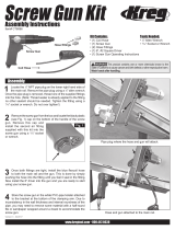
WARNING
PERSONAL PROTECTIVE EQUIPMENT
You must wear appropriate protective equipment when operating, servicing, or when in the
operating area of the equipment to help protect you from serious injury, including eye injury,
inhalation of toxic fumes, burns, and hearing loss. This equipment includes but is not limited to:
• Protective eyewear
• Clothing and respirator as recommended by the fluid and solvent manufacturer
•Gloves
• Hearing protection
TOXIC FLUID OR FUMES HAZARD
Toxic fluids or fumes can cause serious injury or death if splashed in the eyes or on skin,
inhaled, or swallowed.
• Read MSDS’s to know the specific hazards of the fluids you are using.
• Store hazardous fluid in approved containers, and dispose of it according to applicable
guidelines.
SKIN INJECTION HAZARD
High-pressure fluid from gun, hose leaks, or ruptured components will pierce skin. This may
look like just a cut, but it is a serious injury that can result in amputation. Get immediate
surgical treatment.
• Do not point gun at anyone or at any part of the body.
• Do not put your hand over the spray tip.
• Do not stop or deflect leaks with your hand, body, glove, or rag.
• Engage trigger lock when not spraying.
•Follow Pressure Relief Procedure in this manual, when you stop spraying and before
cleaning, checking, or servicing equipment.
PRESSURIZED EQUIPMENT HAZARD
Fluid from the gun/dispense valve, leaks, or ruptured components can splash in the eyes or on
skin and cause serious injury.
•Follow Pressure Relief Procedure in this manual, when you stop spraying and before
cleaning, checking, or servicing equipment.
• Tighten all fluid connections before operating the equipment.
• Check hoses, tubes, and couplings daily. Replace worn or damaged parts immediately.
Warnings
4 311338J
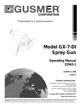
FIRE AND EXPLOSION HAZARD
Flammable fumes, such as solvent and paint fumes, in work area can ignite or explode. To
help prevent fire and explosion:
• Use equipment only in well ventilated area.
• Eliminate all ignition sources; such as pilot lights, cigarettes, portable electric lamps, and
plastic drop cloths (potential static arc).
• Keep work area free of debris, including solvent, rags and gasoline.
• Do not plug or unplug power cords, or turn power or light switches on or off when flammable
fumes are present.
• Ground all equipment in the work area. See Grounding instructions.
• Use only grounded hoses.
• Hold gun firmly to side of grounded pail when triggering into pail.
• If there is static sparking or you feel a shock, stop operation immediately. Do not use
equipment until you identify and correct the problem.
• Keep a working fire extinguisher in the work area.
EQUIPMENT MISUSE HAZARD
Misuse can cause death or serious injury.
• Do not operate the unit when fatigued or under the influence of drugs or alcohol.
• Do not exceed the maximum working pressure or temperature rating of the lowest rated
system component. See Technical Data in all equipment manuals.
• Use fluids and solvents that are compatible with equipment wetted parts. See Technical
Data in all equipment manuals. Read fluid and solvent manufacturer’s warnings. For com-
plete information about your material, request MSDS forms from distributor or retailer.
• Check equipment daily. Repair or replace worn or damaged parts immediately with genuine
Graco/Gusmer replacement parts only.
• Do not alter or modify equipment.
• Use equipment only for its intended purpose. Call your Graco/Gusmer distributor for infor-
mation.
• Route hoses and cables away from traffic areas, sharp edges, moving parts, and hot sur-
faces.
• Do not kink or over bend hoses or use hoses to pull equipment.
• Keep children and animals away from work area.
• Comply with all applicable safety regulations.
PRESSURIZED ALUMINUM PARTS HAZARD
Do not use 1,1,1-trichloroethane, methylene chloride, other halogenated hydrocarbon solvents
or fluids containing such solvents in pressurized aluminum equipment. Such use can cause
serious chemical reaction and equipment rupture, and result in death, serious injury, and prop-
erty damage.
WARNING

Important Two-Component Material Information
311338J 5
Important Two-Component Material Information
Isocyanates (ISO) are catalysts used in two
component materials.
Isocyanate Conditions
Material Self-ignition
Keep Components A and B(R)
Separate
Moisture Sensitivity of
Isocyanates
Exposure to moisture (such as humidity) will
cause ISO to partially cure; forming small,
hard, abrasive crystals, which become sus-
pended in the fluid. Eventually a film will form
on the surface and the ISO will begin to gel,
increasing in viscosity.
NOTE: The amount of film formation and rate
of crystallization varies depending on the blend
of ISO, the humidity, and the temperature.
Spraying or dispensing materials containing iso-
cyanates creates potentially harmful mists,
vapors, and atomized particulates.
Read material manufacturer’s warnings and
material MSDS to know specific hazards and
precautions related to isocyanates.
Prevent inhalation of isocyanate mists, vapors,
and atomized particulates by providing sufficient
ventilation in the work area. If sufficient ventila-
tion is not available, a supplied-air respirator is
required for everyone in the work area.
To prevent contact with isocyanates, appropriate
personal protective equipment, including chemi-
cally impermeable gloves, boots, aprons, and
goggles, is also required for everyone in the work
area.
Some materials may become self-igniting if
applied too thick. Read material manufacturer’s
warnings and material MSDS.
Cross-contamination can result in cured material
in fluid lines which could cause serious injury or
damage equipment. To prevent cross-contamina-
tion:
• Never interchange component A and compo-
nent B(R) wetted parts.
• Never use solvent on one side if it has been
contaminated from the other side.
NOTICE
Partially cured ISO will reduce performance
and the life of all wetted parts.
• Always use a sealed container with a
desiccant dryer in the vent, or a nitrogen
atmosphere. Never store ISO in an open
container.
• Keep the ISO pump wet cup or reservoir
(if installed) filled with appropriate lubri-
cant. The lubricant creates a barrier
between the ISO and the atmosphere.
• Use only moisture-proof hoses compati-
ble with ISO.
• Never use reclaimed solvents, which
may contain moisture. Always keep sol-
vent containers closed when not in use.
• Always lubricate threaded parts with an
appropriate lubricant when reassem-
bling.

Important Two-Component Material Information
6 311338J
Foam Resins with 245 fa
Blowing Agents
Some foam blowing agents will froth at temper-
atures above 90°F (33°C) when not under
pressure, especially if agitated. To reduce
frothing, minimize preheating in a circulation
system.

Important Two-Component Material Information
311338J 7
Overall View
8 311338J
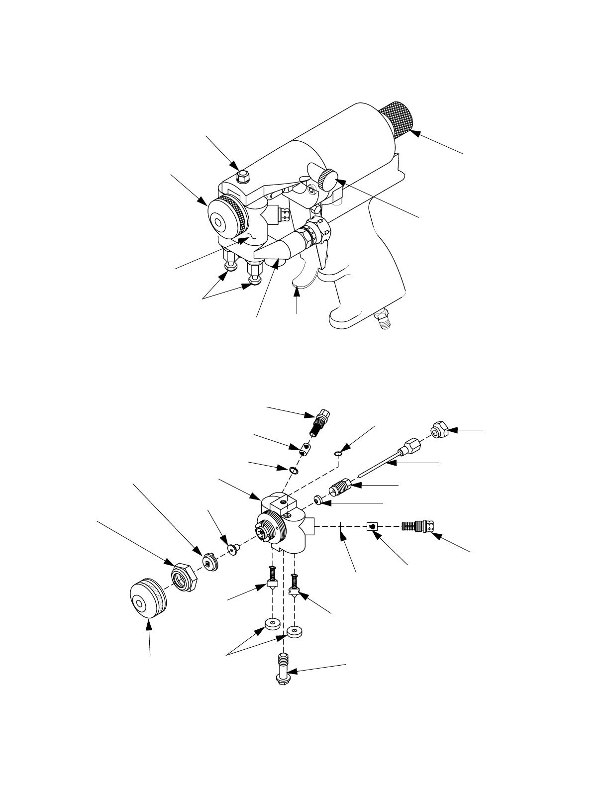
Overall View
Centerline Components
125 PSI MAX
Trigger
Air Cap Air
Adjustment
Valve
Safety Stop
Gun Block
Air Cap
Gun Block
Manual
Coupling
Mounting Screw
Valves
Block
FIG. 1: GX-8P Overall View
B-Screen Screw
Screen
Gun Block
Screen
Mixing
Pattern Control
PCD
Air Cap
B-Check
Coupling
Coupling Block
A-Check
Screen
A-Screen
Screen
Rear Seal
Packing Nut
Valving Rod
Jam Nut
O-Ring
Module
Disc (PCD)
Retainer
Valve
Block Gasket
Mounting Screw
Valve
Retainer
Retainer
Screw
Assembly
FIG. 2: GX-8P Centerline Components
Overall View
311338J 9
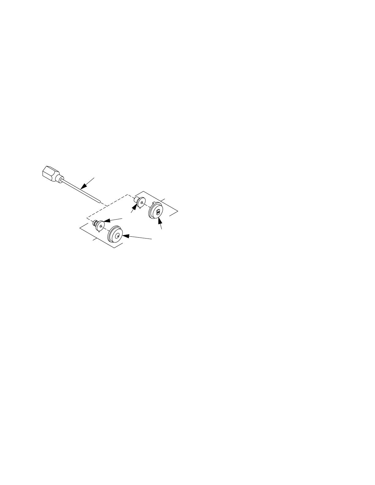
Mixing Module
Graco offers a variety of spray tip configura-
tions to meet most applications that spray
fast-reaction chemical systems at low outputs.
GX-8P spray tip components consist of a Pat-
tern Control Disc (PCD) and a Mixing Module
(Figure 3). Tip components are available in a
range of sizes in both round and fan spray pat-
terns. Please contact your authorized Graco
distributor to help you determine the best con-
figurations for your specific application.
Valving Rod
Mixing
Pattern
Fan Spray
Assembly
Pattern
Round
Spray Pattern
Module
Control
Disc (PCD)
FIG. 3: Mixing Module & PCD
Operation Basics
10 311338J
Operation Basics
Grounding
Check your local electrical code and propor-
tioner manual for detailed grounding instruc-
tions.
Ground spray gun through connection to
Graco-approved grounded fluid supply hose.
Safety Position
GX-8P guns have a two-position safety stop.
When engaged, it prevents accidental trigger-
ing of gun during servicing or down time. When
disengaged, it allows gun to dispense.
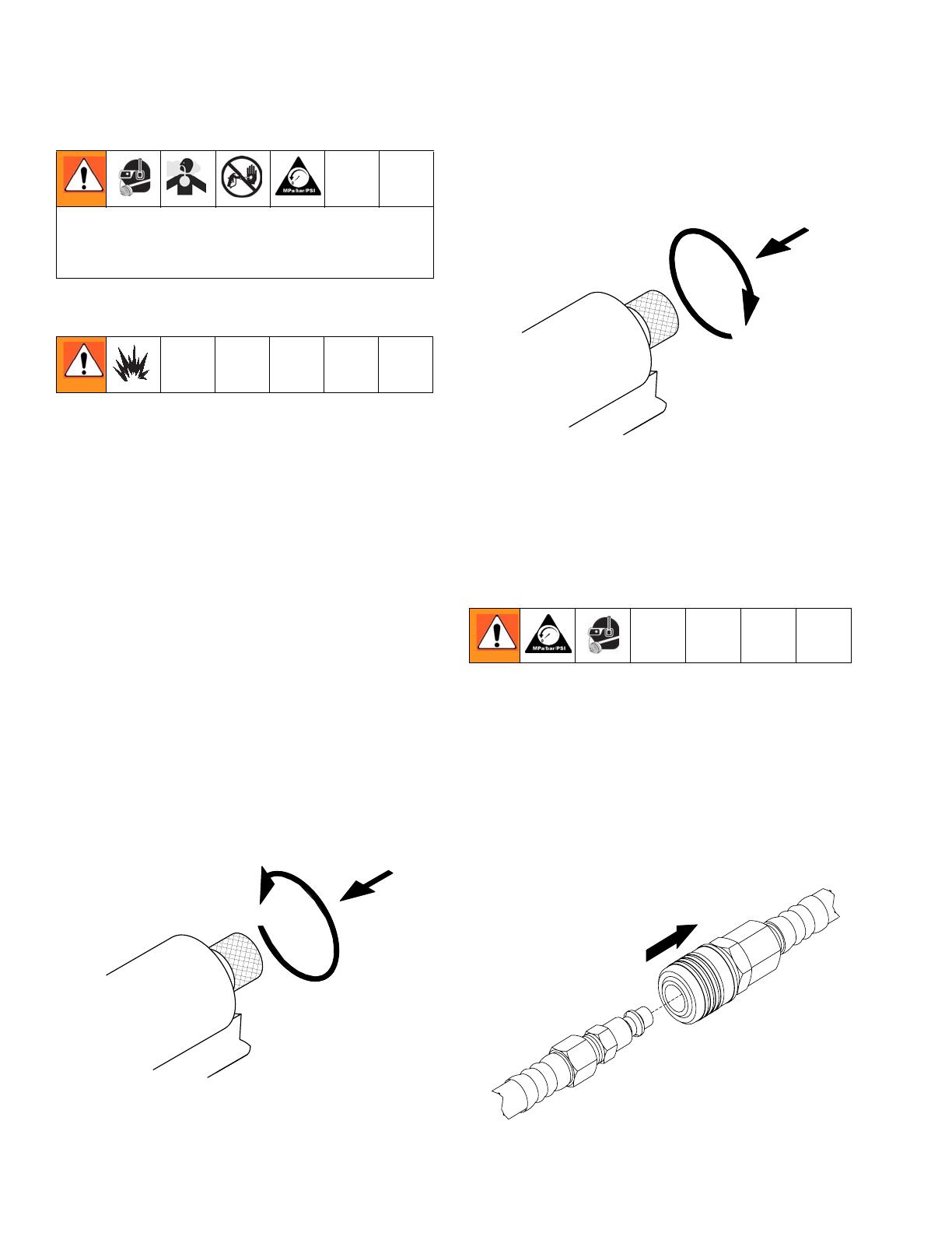
Engage Safety Stop
To engage safety stop, push in and turn safety
stop clockwise to place gun in CLOSED safety
position.
FIG. 4: Safety Stop - Engaged
Disengage Safety Stop
To disengage safety stop, push in and turn
safety stop counterclockwise to place gun in
OPEN position.
FIG. 5: Safety Stop - Disengaged
Air Hose Connection
Connect Air Hoses
Pull back sleeve of female fitting, insert male
fitting and slide sleeve forward to secure con-
nection.
Disconnect Air Hoses
Pull back sleeve of female fitting and pull out
male fitting.
To prevent accidental gun operation, always
disconnect air supply before servicing gun or
anytime gun is not in use.
Engage the
Safety Stop
125 PSI MAX
125 PSI MAX
Disengage the
Safety Stop
1
Pull Sleeve
Operation Basics
311338J 11
FIG. 6: Disconnect Air Hose
Coupling Block
Chemical hoses are joined to gun block by a
coupling block to ease installation and removal
of gun.
Manual Valves
Two manual valves located on coupling block
control flow of each chemical component to
gun.
NOTE: Triggering gun with manual valves
closed may cause crossover if any residual
chemical remains in gun ports.
Open Manual Valves
Use 5/16 in. nut driver to turn manual valve
counterclockwise approximately three full
turns.
FIG. 7: Open Manual Valves
Close Manual Valves
Use 5/16 in. nut driver to turn manual valve
fully clockwise.
Installation and Removal
Install Coupling Block
1. Replace nicked, damaged, or worn cou-
pling block gaskets.
2. Ensure A-(isocyanate) and B-(resin) check
valves are inserted into their proper
recesses in gun block. Isocyanate valve is
notched for easy identification.
Never open manual valve unless coupling
block is secured to gun or unless you point
gun into waste container.
Coupling
Block
Manual
Valves
To prevent accidental gun operation, always
set safety stop to CLOSED, close both man-
ual valves, and disconnect air supply.
To prevent release of pressurized chemicals,
close both manual valves before coupling
block is removed.
Operation Basics
12 311338J
3. Fit coupling block into gun block and insert
coupling block mounting screw. Use 5/16
in. nut driver to tighten to gun block.
FIG. 8: Install Coupling Block
Remove Coupling Block
1. CLOSE safety stop.
2. Disconnect air hose.
3. Close both manual valves.
4. Remove coupling block mounting screw.
5. Separate coupling block from gun.
6. Wipe mating surfaces of gun block and
coupling block to remove residual chemi-
cals.
7. Cover exposed openings with grease.
NOTE: To avoid accidental gun operation,
ensure coupling block manual valves are
closed before attempting to service gun, or any
time gun is not in use.
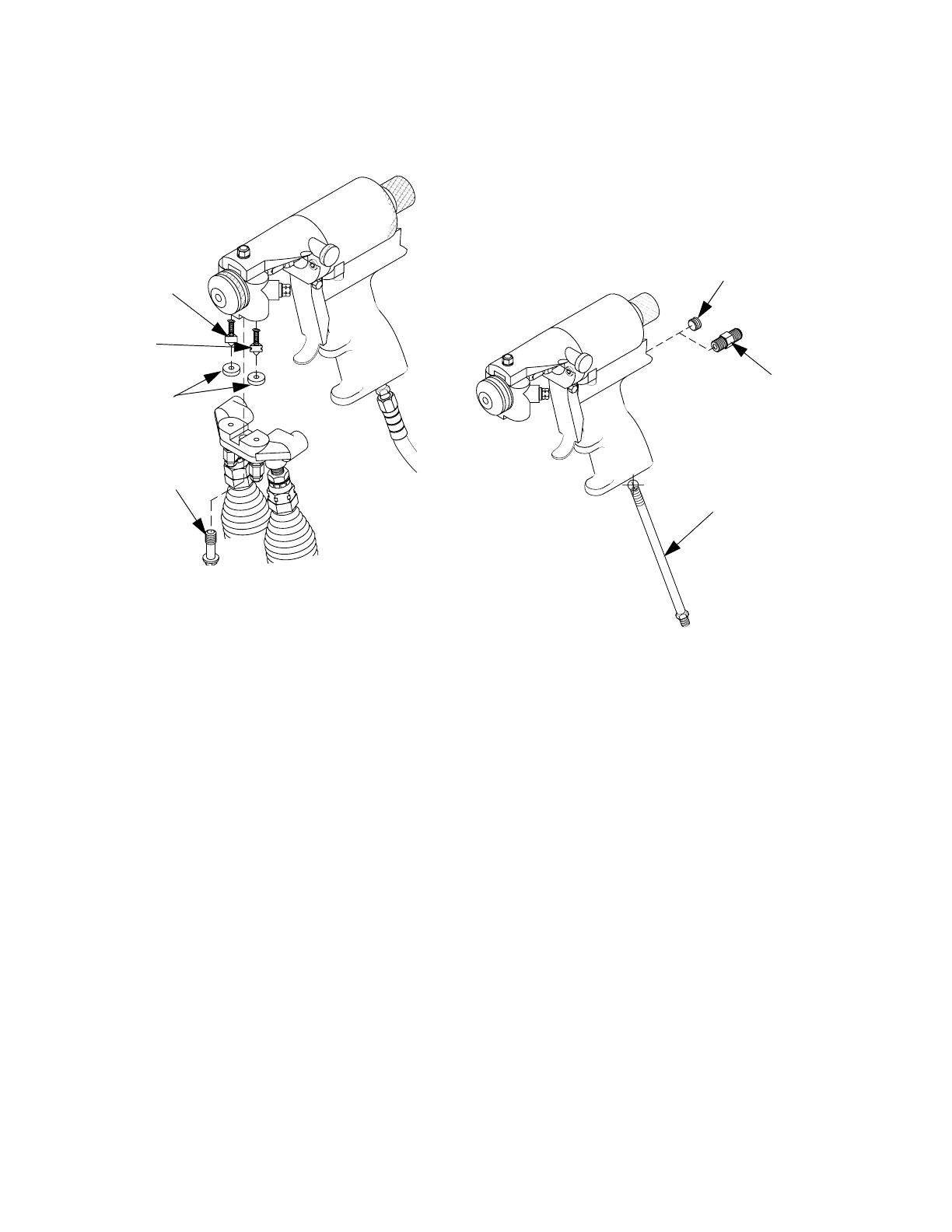
Air Inlet Configuration
There are two configurations for the air inlet. In
the standard configuration, the air inlet is at
base of handle. In the alternate configuration,
the air inlet is at rear of gun.
FIG. 9: Air Inlet Configuration
To change to alternate configuration:
1. Use 6 in. adjustable wrench to remove 4 in.
pipe nipple from base of gun.
2. Use 3/16 in. hex key to remove 1/8 in. pipe
plug from rear of gun.
3. Use 3/16 in. hex key to install 1/8 in. pipe
plug in location previously occupied by 4 in.
pipe nipple.
4. Use 6 in. adjustable wrench to install pipe
nipple in location previously occupied by
1/8 in. pipe plug.
125 PSI MAX
B-Check
Valve
A-Check
Valve
Coupling Block
Gaskets
Coupling Screw
Mounting Screw
125 PSI MAX
Pipe Plug
Optional
Pipe Plug
Pipe
Nipple

Operation Basics
311338J 13
Mixing Module and PCD
Installation
1. Loosen air cap by hand and remove.
2. Install mixing module:
a. Disconnect gun from coupling block.
b. Connect air supply to gun.
c. Set safety stop to OPEN.
d. Hold down trigger and place module
over tip of valving rod.
e. Align keying pin with slot in gun block
and keep gun trigger held down.
3. Install PCD:
a. Hold down gun trigger and thread PCD
retainer in place by hand.
b. Use 10 in. adjustable wrench to care-
fully tighten PCD retainer until snug
enough to ensure no leak will occur.
c. Release gun trigger.
4. Install air cap and tighten by hand.
5. Adjust valving rod (see Valving Rod
Adjustment, page 14).

Operation Basics
14 311338J
Valving Rod Adjustment
Valving rod should not require adjustment if it
was shipped from factory with mixing module
and PCD installed. Valving rod should only re-
quire adjustment when:
• Piston/rod assembly/ring is changed
• Valving rod is changed
• PCD is installed or changed
• Mixing module is installed or changed
To adjust valving rod:
1. Perform Clean Spray Gun Procedure,(see
page 18.
2. Connect air supply to gun.
3. Use 5/16 in. open-end wrench to loosen
packing nut 3 or 4 turns. This relieves pres-
sure between seals and makes adjustment
easier.
FIG. 10: Valving Rod Adjustments
4. Use 3/8 in. wrench on hex-shaped valving
rod shank and 1/2 in. wrench on jam nut to
loosen and back it away from valving rod by
3 or 4 full turns. Then move valving rod
toward gun cylinder. Turn valving rod shank
2 or 3 full turns clockwise.
5. Slowly turn valving rod counterclockwise to
move it toward PCD until resistance is felt.
Valving rod tip should touch inside spheri-
cal surface of PCD.
6. Carefully maintain 3/8 in. wrench in position
and tighten jam nut up against valving rod
shank to lock adjustment into place.
7. Retighten packing nut.
8. Check rear safety stop by attempting to dis-
engage it. If knob will not turn, valving rod
is adjusted too far forward. Repeat steps 3 -
7. Make sure not to adjust valving rod past
the point resistance is felt. If safety stop dis-
engages, proceed to step 9.
9. Trigger gun with safety stop disengaged to
confirm rear seal adjustment. Make sure
rod moves freely. If not, loosen packing nut
slightly until it does. Start to spray and
check for chemical seepage from packing
nut and retighten if necessary.
NOTE: If valving rod required adjustment as
part of initial mixing module and PCD installa-
tion on a new spray gun, proceed to Initial Set
Up, page 15.
Valving Rod
Assembly
Jam Nut
Packing
Nut

Operation Basics
311338J 15
Initial Set Up
1. Remove coupling block from gun.
2. Use two 6 in. adjustable wrenches to install
female quick disconnect fitting onto air sup-
ply hose bundled with chemical supply
hoses.
3. Use two 6 in. adjustable wrenches to con-
nect A-isocyanate hose (red-taped) to
notched fitting on coupling block. Connect
B-resin hose (blue-taped) to fitting without
notches on coupling block.
4. Close both manual valves.
5. Pressurize A and B chemical hoses and
check for leaks (see Proportioner manual
as needed).
6. Bleed air from chemical hoses:
a. Hold coupling block with exit ports
pointed into waste container.
b. Use 5/16 in. nut driver to open each
manual valve; this allows any trapped
air to escape. Bleed each side for a
short time until chemicals leaving hoses
are free of air.
c. Close both manual valves.
7. Use cloth soaked in gun cleaner to clean
coupling block and mating surfaces.
8. CLOSE safety stop.
9. Install coupling block to gun.
10.Proceed with daily start-up and shutdown
procedures as required.
NOTICE
Do not apply grease to mating surfaces of
coupling block to avoid accumulation of dirt
and other contaminants.

Operation Basics
16 311338J
Daily Start-up
1. Connect air supply to gun.
2. Adjust air cap adjustment valve. Turn knob
counterclockwise to open valve and clock-
wise to close valve.
3. Open both manual valves.
4. OPEN safety stop.
5. Test spray on a disposable surface and
evaluate.
Daily Shutdown
NOTE: Follow daily shutdown procedure when
gun is out of service for any length of time, or
for mid- or end-of-day service. See Clean
Spray Gun Procedure, page 18.
1. CLOSE safety stop.
2. Close both manual valves.
3. Disconnect air supply from gun.
4. Shut down proportioning unit as required.
5. Clean as required (see Clean Spray Gun
Procedure, page 18).
NOTE: Disassembling gun for daily cleaning is
not recommended if gun has been operating
properly. However, if gun is removed from cou-
pling block, it must be flushed and cleaned
thoroughly.
Ensure gun is attached to coupling block and
air hose. Ensure proportioning unit is at
desired temperature and pressure. Properly
ground equipment to avoid static sparking
that may result in fire or explosion.
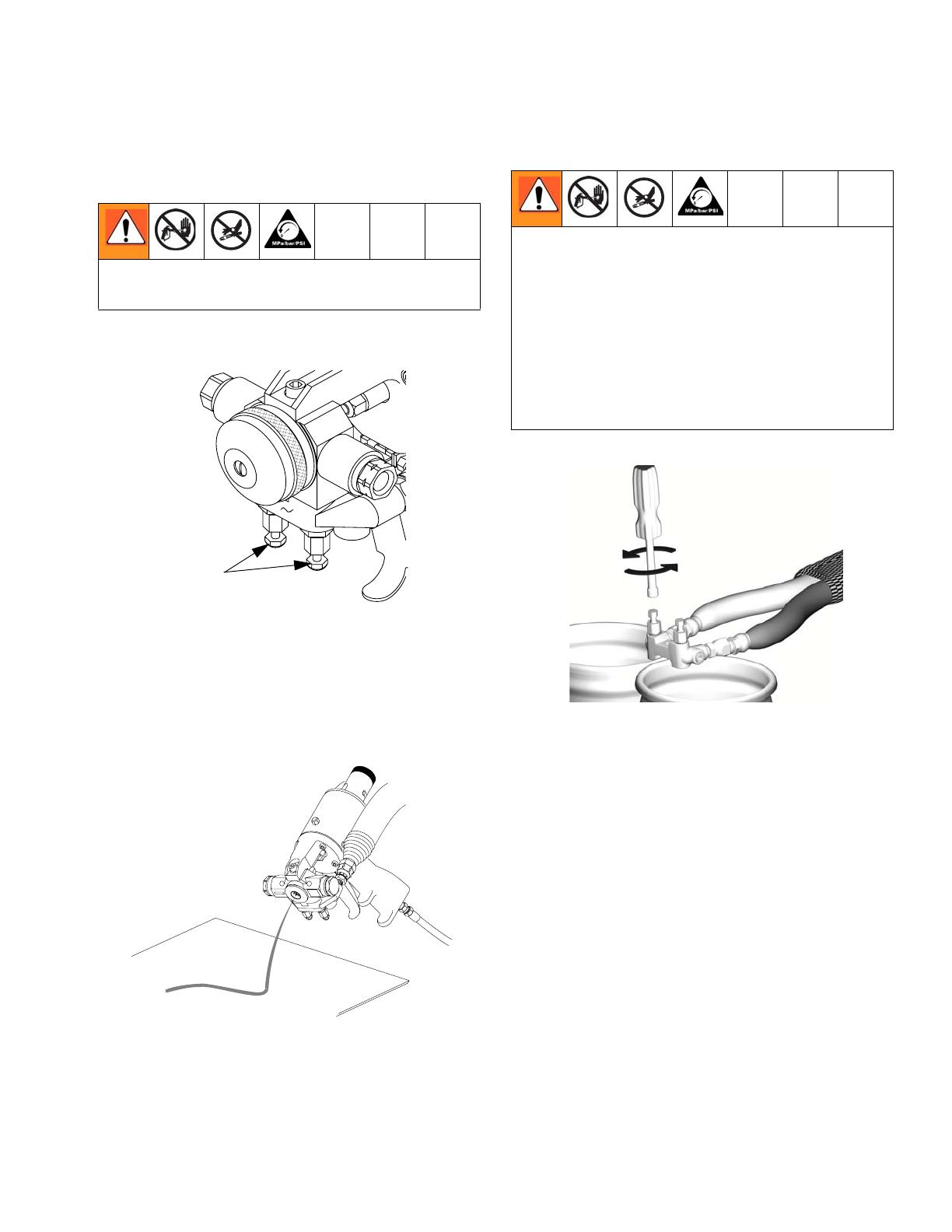
Pressure Relief Procedure
311338J 17
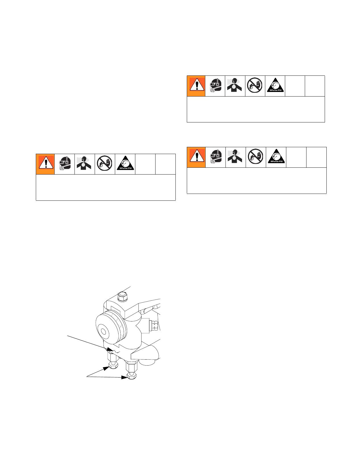
Pressure Relief
Procedure
1. Close both manual valves.
FIG. 11: Close Manual Valves
2. OPEN safety stop.
3. Trigger gun onto cardboard or into waste
container to relieve pressure.
FIG. 12: Trigger Gun
4. Release gun trigger, CLOSE safety stop,
and close manual valves.
FIG. 13: Open Manual Valves
Relieve pressure before cleaning or repairing
gun.
Manual Valves
!
2
If fluid in hose and proportioner is still under
pressure, follow Pressure Relief Procedure in
proportioner manual
To relieve pressure in hose after gun is
removed, place fluid manifold over containers,
facing away from you. Very carefully open
fluid valves (FIG. 13). Under high pressure,
fluid will spray sideways from fluid ports.
Maintenance
18 311338J
Maintenance
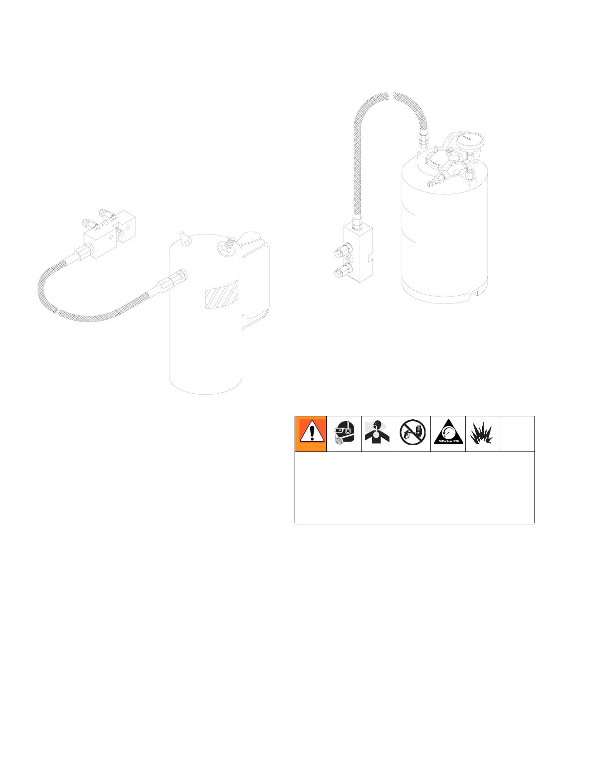
Gun Service Kits
Use either 1-Quart Gun Service Kit (296980)
or 3-Gallon Gun Service Kit (296981) to per-
form daily flushing of spray gun without disas-
sembly.
FIG. 14: 1-Quart Gun Service Kit
For more information about 1-Quart Gun Ser-
vice Kit, see Manual 311340.
FIG. 15: 3-Gallon Gun Service Kit
For more information about 3-Gallon Gun Ser-
vice Kit, see Manual 311341.
Clean Spray Gun Procedure
Thoroughly flush gun block with gun cleaner
before removing valving rod or mixing compo-
nents from gun block. Also allow chemicals in
spray gun to cool before cleaning.
This procedure makes use of the 1-Quart or
3-Gallon Gun Service Kit.
1. CLOSE safety stop.
2. Close both manual valves.
3. Remove gun from coupling block.
To avoid static sparking that may result in fire
or explosion, ensure all equipment in cleaning
procedure is grounded. Do not clean on or
near foamed or coated surfaces or any other
flammable surfaces or objects.

Maintenance
311338J 19
4. Attach service block of gun service kit to
spray gun, and then tighten using 5/16 in.
nut driver.
5. Pressurize service kit container up to 100
psi. DO NOT EXCEED 100 psi (0.7 MPa, 7
bar).
6. Clean gun:
a. Set safety stop to OPEN.
b. Open either manual valve on service
block.
c. Trigger gun and gun service kit simulta-
neously with gun aimed into waste con-
tainer.
d. Release both triggers and close manual
valves on service block.
e. Repeat procedure for other side of gun.
f. After initial cleaning, remove air cap,
PCD retainer, and PCD. Flush a second
time to ensure thorough cleaning.
7. CLOSE safety stop.
8. Disconnect air supply from gun.
9. Remove service block of gun service kit
from gun.
10.Clean screens, check valves and screen
screw (see Service Screen Screw, page
20.
NOTE: Inspect air cap, PCD, mixing module,
and gun block for build up of material and
clean as required.
Do not use metal cleaning devices to clean
plastic components.
Flush Gun
1. CLOSE safety stop.
2. Close both manual valves.
3. Loosen B-Screen screw and then remove
by hand.
4. Use flush can to thoroughly flush screen
screw and screen screw cavity.
5. Loosen A-Screen screw and then remove
by hand.
6. Use flush can to thoroughly flush screen
screw and screen screw cavity.
7. Service gun, see Maintenance proce-
dures, page 18.
To avoid static sparking that may result in fire
or explosion, ensure all equipment in flushing
procedure is grounded. Do not flush on or
near foamed or coated surfaces.

Repair
20 311338J
Repair
Service Screen Screw
1. Flush gun see Clean Spray Gun Proce-
dure, page 18.
2. Unthread screen screw from gun block.
3. Remove screen screw retainer before
removing screen.
4. Remove screen from screen screw. Soak in
gun cleaner or replace if clogged or dirty.
5. Clean screen screw cavity. If any particles
are visible, clean with clean out drills and
flush with gun cleaner.
NOTE: Any material left in cavity on down-
stream side of screen will clog mixing module.
6. Inspect screen screw seal for damage.
Replace if necessary.
7. Reinstall screen screw in gun block. Ensure
it is tight.
8. Flush gun with mixing module removed.
Remove Check Valve
Check valves are located in cavities of gun
block under each coupling block gasket. Check
valves are triangular pieces with a spring insert-
ed in one end. The isocyanate valve is notched
for easy identification.
To remove check valve:
1. Clean gun (see Clean Spray Gun Proce-
dure, page 18).
2. Use check valve seal removal/cleaning tool
to remove gaskets from recesses in cou-
pling block. Inspect gaskets for damage
and replace if necessary.
3. Remove check valves. If valve does not
come out easily, insert machined end of
removal/cleaning tool over valve and rotate
it while extracting valve.
4. Clean valves and springs with gun cleaner.
Inspect for damage and replace if neces-
sary.
5. Inspect each check valve cavity. Use clean-
ing tool to remove any visible particles. Use
gun cleaner to flush thoroughly.
6. Insert each check valve into its cavity
spring end first. Ensure check valve is ori-
ented correctly. Isocyanate valve is notched
for easy identification.
7. Install coupling block gaskets.
Shutdown proportioner and allow chemicals
to cool before servicing gun.
To avoid static sparking that may result in fire
or explosion, ensure all equipment in flushing
procedure is grounded. Do not flush on or
near foamed or coated surfaces.
To avoid static sparking that may result in fire
or explosion, ensure all equipment in flushing
procedure is grounded. Do not flush on or
near foamed or coated surfaces.
/