Simplicity BLOWER, BILLY GOAT User manual
- Category
- Air blowers/dryers
- Type
- User manual
This manual is also suitable for

Part No 430316 (D)
Form No F072407A
1
QB554HC Owner’s Manual
Patent 6253416
BILLY GOAT QB554HC BLOWER
Owner's Manual
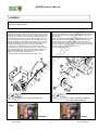
Accessories
CASTER KIT
To improve
maneuverability on
hard paved surfaces.
P/N 430291
Not for Reproduction

Part No 430316 Form No F072407A
2
QB554HC Owner’s Manual
ABOUT THIS MANUAL
THANK YOU for purchasing a BILLY GOAT
®
QB Blower. Your new machine has been carefully designed and
manufactured to provide years of reliable and productive service. This manual provides complete operating and
maintenance instructions that will help to maintain your QB Blower in top running order. Read this manual carefully
before assembling, operating, or servicing your equipment.
CONTENTS
SERIAL PLATE DATA AND SPECIFICATIONS 3
GENERAL SAFETY 4 -5
SOUND AND VIBRATION 6
INSTRUCTION LABELS 7
PACKING CHECKLIST 8
ASSEMBLY 9
OPERATION 10-11
MAINTENANCE 12
TROUBLESHOOTING AND WARRANTY PROCEDURE 13
ILLUSTRATED PARTS LIST 14
PARTS LIST 15
MAINTENANCE RECORD 16
Not for Reproduction

Part No 430316 Form No F072407A
3
QB554HC Owner’s Manual
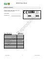
SERIAL PLATE DATA
Record the model number, serial number, date of
purchase, and where purchased.
Purchase Date:
Purchased From:
Specifications
QB554HC
Engine: HP 5.0 HP (3.73 Kw)
Engine: Model GC160AQHA
Engine: Type HONDA OHC
Engine: Fuel Capacity 2.1 qt. (2.0L)
Engine: Oil Capacity 0.63 qt. (0.6L)
Total Unit Weight: 98# (44.5 Kg)
Overall Length: 51.75” (1.31m)
Overall Width 28.5” (0.72m)
Overall Height 39” (0.99m)
Lwa at operator position 106dB(a)
Vibration at operator position .74 g (7.3 m/s
2
)
Not for Reproduction

Part No 430316 Form No F072407A
4
QB554HC Owner’s Manual
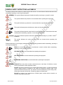
GENERAL SAFETY INSTRUCTIONS and SYMBOLS
The safety symbols shown below are used throughout this manual. You should become familiar with them before
assembling, operating, or servicing this equipment.
This symbol indicates important information that will prevent injury to yourself or others.
This symbol indicates ear protection is recommended when operating this equipment.
This symbol indicates eye protection is recommended when operating this equipment.
This symbol indicates gloves should be worn when servicing this equipment.
This symbol indicates that this manual and the engine manufacturer’s manual should be read
carefully before assembling, operation, or servicing this equipment.
This symbol indicates important information that will prevent damage to your BILLY GOAT
®
QB Blower.
This symbol indicates the engine oil level should be checked before operating this
equipment.
Read and make sure you thoroughly understand the following safety precautions before assembling, operating or
servicing this equipment:
READ this manual and the engine manufacturer’s manual carefully before assembling,
operating, or servicing this equipment.
EAR PROTECTION is recommended when operating this equipment.
EYE PROTECTION is recommended when operating this equipment.
BREATHING PROTECTION is recommended when operating this equipment.
EXHAUST from this product contains chemicals known to the State of California to cause
cancer, birth defects or other reproductive harm.
DO NOT operate this equipment on any unimproved forested, brushy, or grass covered land
unless a spark arrester is installed on the muffler as required by Section 4442 of the
California Public Resources Code. The arrester must be maintained in good working order.
Other states may have similar laws. Federal laws apply on federal lands.
DO NOT run engine in an enclosed area. Exhaust gases contain carbon monoxide, an
odorless and possibly fatal poison.
Not for Reproduction

Part No 430316 Form No F072407A
5
QB554HC Owner’s Manual
DO NOT run this equipment indoors or in any poorly ventilated area. Refueling outdoors is
recommended.
DO NOT refuel this equipment while the engine is running. Allow engine to cool for at least
two minutes before refueling.
DO NOT store gasoline near an open flame.
DO NOT remove gas cap while engine is running.
DO NOT start or operate engine if strong odor of gasoline is present.
DO NOT start or operate engine if gasoline is spilled. Move equipment away from spill until
gasoline has completely evaporated.
DO NOT smoke while filling the fuel tank.
DO NOT check for spark with spark plug or spark plug wire removed. Use an approved spark
tester.
DO NOT operate engine without a muffler. Inspect muffler periodically and replace if
necessary. If equipped with muffler deflector, inspect deflector periodically and replace if
necessary.
DO NOT operate engine with grass, leaves or other combustible material near the muffler.
DO NOT touch muffler, cylinder, or cooling fins when hot. Contact with hot surfaces may
cause severe burns.
DO NOT leave equipment unattended while in operation.
DO NOT park equipment on a steep grade or slope.
DO NOT operate equipment with bystanders in or near the work area.
DO NOT allow children to operate this equipment.
DO NOT operate equipment with guards removed.
DO NOT operate equipment near hot or burning debris or any toxic or explosive materials.
DO NOT operate equipment on slopes greater than specified in Specifications section of this
manual.
ALWAYS remove spark plug wire when servicing equipment to prevent accidental starting.
ALWAYS check fuel lines and fittings frequently for cracks or leaks. Replace if necessary.
ALWAYS keep hands and feet away from moving or rotating parts.
ALWAYS store fuel in approved safety containers.
DO NOT run this machine with a cracked or damaged impeller under any circumstances.
Not for Reproduction

Part No 430316 Form No F072407A
6
QB554HC Owner’s Manual
SOUND
SOUND LEVEL 106 Db(a) at Operator Position
Sound tests were conducted in accordance with 2000/14/EC, as well as ISO 11094, and were performed on 2-16-
2002 under the conditions listed below.
Sound power level listed is the highest value for this model. Please refer to serial plate on the unit for the sound
power level for your model.
VIBRATION DATA
VIBRATION LEVEL .74g (7.3m/s
2
)
Vibration levels at the operator’s handles were measured in the vertical, lateral and longitudinal directions using
calibrated vibration test equipment. Tests were performed on 5-25-2006 under the conditions listed below.
INTENDED USE
This machine is designed for cleaning outdoor surfaces, where the debris can be effectively blown into a
consolidated area for convenient pickup and removal.
Do not operate if excessive vibration occurs. If excessive vibration occurs, shut engine off immediately and check
for damaged or worn impeller, loose impeller bolt, loose impeller key, loose engine or lodged foreign objects. Note:
See parts list for proper impeller bolt torque specifications. (See trouble shooting section on page 13).
General Conditions: Sunny
Temperature: 60
o
F (15.6
o
C)
Wind Speed: 10 mph (16.1 kmh)
Wind Direction: North
Humidity: 32%
Barometric Pressure: 29.95Hg (761 mm Hg
)
General Conditions: Sunny
Temperature: 89.06
o
F (31.7
o
C)
Wind Speed: 13.6 mph (21.96kph)
Wind Direction: West
Humidity: 22.8%
Barometric Pressure: 29.9Hg (101.35kpa
)
Not for Reproduction

Part No 430316 Form No F072407A
7
QB554HC Owner’s Manual
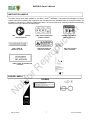
INSTRUCTION LABELS
The labels shown below were installed on your BILLY GOAT
®
QB Blower. If any labels are damaged or missing,
replace them before operating this equipment. Item numbers from the Illustrated Parts List and part numbers are
provided for convenience in ordering replacement labels. The correct position for each label may be determined by
referring to the Figure and Item numbers shown.
LABEL READ OWNERS MANUAL LABEL EAR EYE BREATHING DANGER FLYING DEBRIS
ITEM #44 P/N890301 ITEM# 45 P/N890254 ITEM # 46 P/N 810736
LABEL LEVER QB LABEL EXPLOSIVE FUEL LABEL GUST CONTROL
ITEM #46 P/N 430363 ITEM # 43 P/N 400268 ITEM # 7 P/N 430388
LABEL PATENT QB AIR DIRECTOR
P/N 430400
ENGINE LABELS
HONDA MOTOR CO. , LTD. MADE IN JAPAN
READ OWNER’S MANUAL BEFORE OPERATION.
LIRE LE MANUEL D UTILISATEURAVANT USAGE.
VOR INBETRIEBNAHME UNBEDINGHT BEDIENUNGSANLEITUNG DURCHLESEN.
NO UTILIZAR SINANTES NO HABER LEIDO EL MANUAL
HONDA
Not for Reproduction

Part No 430316 Form No F072407A
8
QB554HC Owner’s Manual
PACKING CHECKLIST
These items should be included in your carton. If any of these parts are missing, contact your dealer.
Your BILLY GOAT
®
QB Blower was shipped in one carton, completely assembled except for the Upper Handle
Assembly, Front Exhaust and Front wheel and bracket. Mounting hardware for the Upper Handle Assembly can be
found in the pre mounted on the lower handle and in the parts bag.
READ all safety instructions before assembling unit.
TAKE CAUTION
when removing the unit from the box the Handle Assembly is attached to the
unit by cables.
PUT OIL IN ENGINE BEFORE STARTING
Boxing Parts Checklist
Front Exhaust Director
P/N-430370
Handle Upper Assembly
P/N-400957
Handle Brace
P/N-400951
Bracket Front
P/N-430270
Front wheel
P/N-430271
Parts Bag & Literature Assy
P/N-430334
Honda 5
PARTS BAG &
LITERATURE ASSY
Warranty card P/N- 400972, Owner’s Manual P/N-430316, Declaration of Conformity P/N-430189.
14
24
18
20
19
58
32
16
Screwcap
5/16-18x1 1/4
8041029 Qty. 1
Screwcap
3/8- 16 x 3 3/4
8041061 Qty. 1
430268 Qty. 1
Ty-wrap 1"
900407 Qty. 3
Washer 1/2 SAE
8172011 Qty. 1
Nut Lock 5/16-18
8160002 Qty. 3
Nut Lock 3/8- 16
8161042 Qty. 1
Washer 5/16 Flat cut
81710003 Qty. 1
Parts bag assembly checklist
Not for Reproduction

Part No 430316 Form No F072407A
9
QB554HC Owner’s Manual
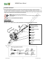
ASSEMBLY
Figure A Figure B
Fig 2.
Incorrect Correct
1.Follow the steps in figures A and B, then securely tighten all hardware shown.
2.Connect spark plug wire.
1. The hardware for attaching the upper handle to the lower is
preinstalled in the proper location in the lower handle. Before the upper
handle can be installed you must remove the hardware from the handle
and reuse it in the same locations. Install upper handle (Item 28), to
preassembled lower handle (item 29) by sliding the upper over and
down the outside of the lower handle. Pull recoil handle from the engine
and place it between rope guides (Item 13). Using screw & lock nut to
install upper handle to lower handle. Finish installing the other side of
the upper handle assembly using screw and lock nut provided.
2. Install front of handle brace (Item 30), to blower housing using
one screw(Item 31), one washer (Item 58) and one lock nut (item 32)
located in the hardware bag. Install rear of handle brace (item 30) to
upper handle vibration mounts using two lock nuts (item 32) also
located in the hardware bag. Hand tighten only.
3. Securely tighten all hardware listed above in steps 1 thru 2.
4. Remove four lock nuts from the front plate and use them to attach the
front wheel bracket (Item 27). Using spacer (Item 18), washer (Item 19),
and Lock Nut (Item 16) to attach Front wheel (Item 23) onto the front
wheel bracket.
NOTE: Front wheel bracket (Item 27) should be mounted with the offset
portion of the bracket toward the ground. This will place the blower
exhaust parallel to the ground. The bracket can be mounted in the
opposite configuration to move the blower exhaust closer to the ground.
5. When ty-wrapping the diverter cable in place please be sure to follow
the correct routing of the cable as shown in Fig. 2.
6. Connect spark plug wire.
Two ½” open ended wrenches
One ½ open-end wrench and two
9/16” open-ended wrenches
Not for Reproduction

Part No 430316 Form No F072407A
10
QB554HC Owner’s Manual
OPERATION
Like all mechanical tools, reasonable care must be used when operating machine.
Inspect machine work area and machine before operating. Make sure that all operators of this
equipment are trained in general machine use and safety.
PUT OIL IN ENGINE BEFORE STARTING
STARTING
ENGINE: See engine manufacturer’s instructions for type and amount of oil and gasoline used. Engine must be
level when checking and filling oil and gasoline.
CHOKE: Operated with choke lever on side of engine.
THROTTLE: Controlled by throttle lever on the handle. Move remote throttle control to fast position. Pull start rope
to start engine.
ENGINE SPEED: Under normal conditions, operate at minimum throttle to accomplish your current cleaning task.
SHUTDOWN: Move throttle lever on the engine slowly to the stop position
IF YOUR UNIT FAILS TO START:
See Troubleshooting on page 13.
HANDLING & TRANSPORTING:
Using two people to lift machine is recommended. Lift holding the handle and handle brace. Secure in place during
transportation. See QB specifications on page 3 for unit weight.
Do not use the front grill as an anchor point when securing the unit for transport.
Never lift the machine while the engine is running.
BLOWING OPERATION
Your Billy Goat QB blower is equipped with an exhaust director to allow the operator to direct the air stream up or
down as required to assist in moving debris. This feature is extremely useful when debris has piled up to the point
that it cannot be blown any farther. The air stream can be directed upward to blow the top of the debris pile over
and allow the operator to continue moving more debris farther.
Not for Reproduction

Part No 430316 Form No F072407A
11
QB554HC Owner’s Manual
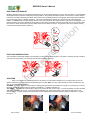
ADJUSTING GUST EXHAUST
Releasing the lever allows air to be directed upward during use to avoid blowing debris into cars or other structures, or to avoid blowing
landscaped areas that would be damaged by the high-speed air. This position also allows operator to maneuver the machine relative
to the work area without disturbing the debris. When the lever is over halfway back and in lock position this will direct the air parallel to
the ground for the majority of blowing operations. The hand control allows the operator to lock the air stream in this straight out
position. To LOCK the air in position simply pull back on the lever and pull the lever sideways to the right until the lock engages. See
instruction label on the control. With the lever fully drawn to the handle, this position directs the air stream down at the ground to allow
the operator to deliver the maximum power to debris that is stuck or difficult to remove. This position is also very useful for cleaning
out cracks and expansion joints in pavement.
FRONT DISCHARGE POSITION
The removable front discharge adapter can be slipped on to direct the air stream forward. This option is extremely useful for cleaning
out long cracks in pavement or for cleaning under bushes or building overhangs.
Up
Down
Straight
& Lock
ADJUSTING
When you lock the lever, the default position of air director is in the middle or straight out. If you want to raise or lower air
director lock position you must adjust the threaded fitting on the cable. Note: You will not get full range of motion of air director If you
raise or lower default locking position.
TO RAISE, 1. Lock the air director in place at the handle by pulling on the lever then slide it over to right. 2. Loosen the top nut on the
threaded cable fitting until the air director position is satisfactory. 3. Tighten the bottom nut.
TO LOWER, 1. Lock the lever at the handle by pulling on the lever then slide it over to right. 2. Loosen the bottom nut on the threaded
cable fitting and back it off 1/4 inch. 3. Pull the threaded cable fitting up while pushing down on the air director then check for air
director position. 4. Loosen or tighten the same bottom nut then repeat step 3 until the air director position is satisfactory. 5. Tighten
the top nut
Not for Reproduction

Part No 430316 Form No F072407A
12
QB554HC Owner’s Manual
MAINTENANCE
P
ERIODIC MAINTENANCE
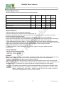
Periodic maintenance should be performed at the following intervals:
Maintenance Operation Every
Use
Daily or Every
5 Hours
Every 25
Hours
Every 50
Hours
Every
100-150
Hours
Inspect for worn or damaged parts.
z
Check for excessive vibration
z
Inspect Impeller for cracks or damage
z
Engine (See Engine Manual)
z
Lubricate wheels
z
Inspect for loose parts.
z
IMPELLER REMOVAL
1. Wait for engine to cool and disconnect spark plug.
2. Remove front wheel (item 23),and front wheel bracket (item 27).
3. Remove housing front plate (item 4), by removing nine (9) screws (item 12), around outside of front plate.
4. Remove impeller bolt and lock washer.
5. Pull on center hub backplate area only of impeller. If impeller slides off freely, proceed to (step 8).
6. Place two crowbars between center hub backplate area of impeller and housing on opposite sides. Carefully pry
impeller away from engine until it loosens. Using a penetrating oil can help loosen a stuck impeller.
7. If the impeller does not loosen, obtain a 1” (25.4mm) longer bolt of the same diameter and thread type as the
impeller bolt. Thread longer bolt by hand into the crankshaft until bolt bottoms. Using a suitable gear or wheel puller
against the bolt head and the impeller back-plate (near the blades), remove impeller from shaft.
8. Reinstall new impeller in reverse order of removal.
9. Tighten impeller bolt. Torque impeller bolt (see parts list on page 15 for proper impeller bolt torque
specifications).
TIRE AIR PRESSURE
Check at regular intervals and maintain.
Front Tires - 50 Psi (344 kPa).
Rear Tires - 24 Psi (165 kPa).
STORAGE
Never store engine indoors or in enclosed poorly ventilated areas with fuel in tank, where fuel fumes may reach
an open flame, spark or pilot light, as on a furnace, water heater, clothes dryer or other gas appliance.
If engine is to be unused for 30 days or more, prepare as follows:
Remove all gasoline from carburetor and fuel tank to prevent gum deposits from forming on these parts and
causing possible malfunction of engine. Drain fuel outdoors, into an approved container, away from open flame. Be
sure engine is cool. Do not smoke. Run engine until fuel tank is empty and engine runs out of gasoline.
Fuel stabilizer (such as Sta-Bil
TM
) is an acceptable alternative for minimizing the formation of gum
deposits during storage. Add stabilizer to gasoline in storage container or fuel tank. Follow
stabilizer manufacturer’s instructions to determine proper mix ratio. Run engine at least 10
minutes after adding stabilizer to allow it to reach carburetor.
Not for Reproduction

Part No 430316 Form No F072407A
13
QB554HC Owner’s Manual
TROUBLESHOOTING
When servicing engine refer to specific manufacturers engine owner's manual. Engine warranty is covered by the
specific engine manufacturer. If your engine requires warranty or other repair work contact your local servicing
engine dealer. When contacting a dealer for service it is a good idea to have your engine model number available
for reference (See table page 3). If you cannot locate a servicing dealer in your area you can contact the
manufacturers national service organization.
To reach:
American Honda: 800-426-7701
WARRANTY CLAIM PROCEDURE
Should a BILLY GOAT
®
machine fail due to a defect in material and/or workmanship, the owner should make a
warranty claim as follows:
• The machine must be taken to the dealer from whom it was purchased or to an authorized Servicing BILLY
GOAT Dealer.
• The owner must present the remaining half of the Warranty Registration Card, or, if this is not available, the
invoice or receipt.
• The Warranty Claim will be completed by the authorized BILLY GOAT Dealer and submitted to their
respective BILLY GOAT Distributor for their territory Attention: Service Manager. Any parts replaced under
warranty must be tagged and retained for 90 days. The model number and serial number of the unit must
be stated in the Warranty Claim.
• The distributor service manager will sign off on the claim and submit it to BILLY GOAT for consideration.
• The Technical Service Department at BILLY GOAT will study the claim and may request parts to be
returned for examination. BILLY GOAT will notify their conclusions to the distributor service manager from
whom the claim was received.
• The decision by the Technical Service Department at BILLY GOAT to approve or reject a Warranty Claim is
final and binding.
For online product registration go to www.billygoat.com
Problem Possible Cause Solution
Abnormal vibration. · Loose or out of balance impeller. · Check impeller and replace if required.
· Loose en
g
ine. · Check en
g
ine.
En
g
ine will not start. · En
g
ine not in full choke position. · Check choke position.
· Out of gasoline or bad, old gasoline. · Check gasoline.
· Spark Plug wire disconnected. · Connect spark plug wire.
· Gas valve off. · Turn on
g
as valve.
· Dirty air cleaner. · Clean or replace air cleaner. Contact a
qualified service person.
Engine is locked, will not pull
over.
· Engine problem. · Contact an engine servicing dealer for
en
g
ine problems.
Not for Reproduction

Part No 430316 Form No F072407A
14
QB554HC Owner’s Manual
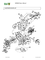
ILLUSTRATED PARTS LIST
Not for Reproduction

Part No 430316 Form No F072407A
15
QB554HC Owner’s Manual
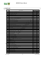
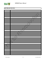
PARTS LIST
PART NO QTY
1 ENGINE - 5.0 HP HONDA 430272 1
2 W ASHER LOCK 5/16 TW ISTED TO O TH 800177 2
3 GUST DIRECTOR QB 430369 1
4 PLATE FRONT & GRILL ASSY 430182 1
5 IMPELLER ASS’Y 430276 1
6 KEY SQUARE 3/16 x 1 3/4" 9201084 1
7 LABEL CONTROL QB HONDA 430388 1
8 AXLE 430181 1
9 W ASHER LOCK 7/16 TW ISTED TO O TH 850132 1
10 SCREW CAP 5/16-24 x 1-1/4 G R. 8 (TO RQUE 31 FT LBS)(42 N.m ) 400389 1
11 LABEL DO NOT FILL WHEN ENGINE IS HOT 400268 1
12 SHEET M ETAL SCREW 1/4 x 3/4 DRILL POINT 430208 9
14 SCREW CAP 5/16-18 x 1 - 1/4 *8041029 7
15 SCREW CAP 1/4 -20 x 2 *8041010 1
16 NUT LO CK 3/8 -16 THN HEIG HT *8161042 1
18 SPACER 1/2 OD x 3.062" 430268 1
19 W ASHER 1/2 SAE 8172011 1
20 CABLE TY 900407 3
21 GRIP 430342 2
22 SCREW CAP 5/16-18 X 2½ *8041034 1
23 W HEEL &TIRE ASSY 8" PNEU 430271 1
24 SCREW CAP, (FRONT AXLE) 3/8-16 x 3 3/4" *8041061 1
25 CONTROL LEVER QB 430332 1
26 W HEEL, REAR 400295 2
27 BRACKET (FRONT W HEEL) 430270 1
28 HANDLE UPPER ASS’Y (incl. item s 14(2), 25, 35(2), 46, 58(2) 430335 1
29 HANDLE LOWER 400950 1
30 HANDLE- BRACE 400951 1
31 SCREW CAP 5/16 -18 x 1¾ *8041031 5
32 NUT LO CK , 5/16-18 HEX *8160002 15
33 BUSHING PIVOT BACK 430323 1
34 SCREW CAP 5/16 -24 NF x 3/4" GR. 5 *8042026 2
35 VIBRATION MOUNT 400173 6
36 PARTS BAG ASS’Y (INCL ITEM S 32(5), 58 (1), 15(1), 37(1), 20(3), 17(3) 430255 1
37 NUT LO CK 1/4 - 20 HEX *8160001 2
38 RING RETAINING ¾ 850230 2
39 BRACKET CONTROL BOX W A QB 430328 1
40 CABLE GUST CONTROL QB 430418 1
41 LABEL DANGER HANDS & FEET 400424 1
43 W ASHER - FLAT 3/4 S.A.E. (3/16 x 1-1/2 x 1/8 ) *8172015 2
44 LABEL DANGER FLYING MATERIAL 810736 1
45 W ASHER 1/4 SAE *8171002 1
46 LABEL LEVER QB 430363 1
47 BUSHING PIVOT FRONT 430349 1
48 GUAR D M UFFLER (COM ES W / ITEM 1 ) YES -
49 SPRING PIVOT EXHAUST 430326 1
50 RIN G RETAINER 5/16" 430327 3
51 LABEL EAR EYE BREATING 890254 1
52 W IRE PIVOT QB EXHAUST 430396 1
54 DEFLECTOR FRONT EXHAUST QB 430370 1
56 FRAME ASS’Y (INCLUDES 41, 44, 51, 59 ) 430374 1
58 W ASHER FLAT CUT 5/16 ( 3/8 ID x 7/8 O D x1/16 ) *8171003 12
59 LABEL READ OW NER'S MANUAL 890301 1
60 NUT PAL 1/4 430409 1
61 W IRE MOUNT DIRECTOR 430391 1
62 SPACER PIVOT W IRE 430390 1
63 W ASHER FLAT FENDER 5/16" 8172020 1
67 STEELMARK LABEL 830113 1
68 BILLY G OAT LABEL CIRC LE 430303 1
69 BILLY GOAT LABEL OVAL 430304 1
ITEM DESCRIPTION
Q B554HC
Not for Reproduction

Part No 430316 Form No F072407A
16
QB554HC Owner’s Manual
MAINTENANCE RECORD
Date Service Performed
Not for Reproduction
-
 1
1
-
 2
2
-
 3
3
-
 4
4
-
 5
5
-
 6
6
-
 7
7
-
 8
8
-
 9
9
-
 10
10
-
 11
11
-
 12
12
-
 13
13
-
 14
14
-
 15
15
-
 16
16


Simplicity BLOWER, BILLY GOAT User manual
- Category
- Air blowers/dryers
- Type
- User manual
- This manual is also suitable for
Ask a question and I''ll find the answer in the document
Finding information in a document is now easier with AI
Related papers
-
Simplicity QUIET BLOW QB994S User manual
-
-
Simplicity FZ1301H User manual
-
-
-
-
Simplicity BLOWER, BILLY GOAT User manual
-
Simplicity F1802SPV User manual
-
-
Other documents
-
Billy Goat QUIET BLOW QB654 User manual
-
-
-
Billy Goat F1302H Owner's manual
-
Unbranded RGC126 User manual
-
Everbilt AM46HD Installation guide
-
-
 Deflect-o 53 User manual
-
Billy Goat F601S User manual
-
Billy Goat F901H User manual
