Page is loading ...

SERVICE MANUAL
For the
Vermont Castings
Please place picture here.
1990 - 1993 D
CONVECTION
UTCHWEST
HEATERS
ODELS:
ll)
arge)
M
2181 (Sma
2183 (Large)
2184 (Extra L

HISTORY OF CHANGES
1990 – 1993 DUTCHWEST CONVECTION HEATERS
Models 2181 (Small), 2183 (Large), and 2184 (Extra Large)
In 1990, Vermont Castings changed the Dutchwest Convection Heaters to improve the
appearance, performance and serviceability of the stoves. The changes include:
• A horizontal brass bar in a convection outlet slot where the top and front meet. This
replaces the earlier two separate screened openings.
• Convection air inlets on the bottom of the stove. These become invisible to the user, and
replace earlier screened openings on the stove front.
• A modified damper linkage using a ductile-iron ‘crank-shaft’ passing through an adjustable
‘stirrup’ lifter.
• A ceramic fiber insulator around the combustor.
• A larger cook top. It is no longer a separate polished part but part of the stove top. A rope
gasket is used on the under side of the stove top for quick and easy access to the combustor
and damper.
• A heavier catalyst baffle. It is now heavier, and round, and made of ductile-iron, and has a
Sequoia-style round air distributor between it and the catalyst.
• Coal grate sides and front are now optional and the fire screen is optional.
• Latches are helical on un-threaded steel stems.
• An ‘air balance plate’ at the right end of the firebox. This brings room air into the firebox, to
balance the effect of the primary air inlet on the side-load door.
• An air diffuser plate on the inside of the side-load door. This slows the flow of the air into
the firebox.
• A round flue collar on the small and large units. The extra-large uses the
Encore 8” oval
flue collar.
• Heat-reflective coating on the glass panels. This helps them stay clearer. For the extra-
large, there are left and right panels. Glass became standard equipment in 1992.
• Dropped the earlier steel gasket caps for the rocker grates, and substituted a single a cast-
iron panel to form the seal on the left side.
In 1992, Vermont Castings changed the inner tops to include a separate ‘web’ piece between the
damper and the catalyst. Since the web is separate from the main inner top, it can ‘float’ in
response to the high temperatures in that area.
Instructions for installing the new two piece inner top are found in the Repair Procedures Section.

REPAIR PROCEDURES
1990 – 1993 DUTCHWEST CONVECTION HEATERS
Models 2181 (Small), 2183 (Large), and 2184 (Extra Large)
INSTALLING THE TWO PIECE INNER TOP
Tools Required: Phillips and flat screwdrivers, socket wrench with 7/16” socket/open-end wrench,
rubber mallet, and 3 tubes of stove cement, caulking gun, putty knife, rags, hammer, cold chisel,
and wooden block.
1. Remove the top (one bolt in each corner). Since there is a gasketed seam between inner and
outer tops, you won’t need to break a cement seal here.
2. Remove the refractory insulator and combustor.
3. Remove the anchor bolt holding the #29 damper adjuster to the #28 damper. There is a hex
nut on the anchor bolt on the under side of the damper.
4. Rotate #35 damper crank counter-clockwise (as you face left side of the stove) until it
separates from the #36 damper operating rod. Lift the damper and operating crank off along
with adjuster.
5. Lift the front doors (including ash door) and brass bar #60 off the stove front.
6. Remove 2 hex nuts from the studs joining the stove front to the stove sides, above the inner
top.
7. Use a hammer and a wooden block to tap outward on the stove front from inside the firebox.
Once the cement seal is broken, lift the front off and set it aside. If you have left the ash door
on the stove front, do not set the front down vertically--pressure on the ash door can break it or
the stove front.
8. Remove the hex nut and washer from the stud above the right rear corner of the inner top
(joining the right side and the outer back). From inside, tap outward against the right side to
break its cement seal. Pull the right outward and forward at the same time until it clears the
inner back and then lift it off.
9. Tap around the left and rear edges of the inner top to separate it from the inner back and the
left side, and lift it out.
10. Use hammer and cold chisel to clean old cement out of the joints of all parts to be re-used.

11. Work in reverse order to re-assemble. Replacement inner tops include a separate ‘web’ piece
between the catalyst chamber and the damper opening. This web can move separately in
response to the high temperatures in that area.
The web is loosely bolted into place at each end and has Interam gasket to seal its ends. On
installation, the Interam gasket can look too small for the gap it seals. However, this Interam
will expand greatly under heat, and seal the gaps.
It’s worthwhile to do a ‘dry fit’ to ensure that parts fit together well before you cement anything.
Put a heavy bead of stove cement in each joint groove before putting the mating piece of iron
into it. When installing the inner top, be sure to align the inner top with the bypass operating
rod’s hole in the left side so that the bypass gate operates freely without causing the operating
rod to be forced to one side of the hole in the stove’s left side. Adjust the bypass gate so it
closes with only a little pressure.
12. Transfer the original baffle, channel cap, and air distributor from the original inner top to the
new one.
13. When the inner top is in place and the right side is attached and supports the inner top, use
hex bolts and steel tabs to attach the damper to the inner top. After you have positioned the
damper crank, damper operating rod, and adjuster--anchor the adjuster to the damper with a
hex bolt and nut below the damper.
14. Re-attach the stove front, after cementing its seams where it joins the stove sides and the
inner top and the inner bottom. Add the doors.
15. Install the catalytic combustor and insulator. Be sure there is Interam gasket around the
combustor.
16. Re-install the brass bar across the top/front opening.
17. Check the gasketing on the under side of the stove top to ensure a good seal here. Replace
the top. The bolts should be snug but not overly tight; over-tightening can warp the top,
possibly causing leakage.
18. Direct the customer to re-‘cure’ the stove, to acclimate the new inner top to the pressures of
expansion and contraction. Curing is a series of five small fires, with each fire hotter and
longer than the previous one.

INSTALLING THE SHAKER CENTRE GRATE
The shaker centre grate is easy to install in your stove. It should take about ten minutes to replace
it.
Start by removing the grate back and the side half-wall (called ‘air balance plate’ on some models).
Each panel has two bolts holding it in place.
Lift the rear edge of the grate frame (called ‘grate’ in some instructions) and prop it up out of the
way. Now you can lift out the centre grate through the front door and the centre opening of the
frame. There is no hardware holding the centre grate; it sits on ‘saddles’ on the stove’s inner
bottom. Replace the shaker centre grate, putting the edge with the longer teeth toward the front of
the stove. The longer teeth point downward. These prevent coal embers from falling into the pan,
unless you intentionally rock the rockers more than 60 degrees. When you lower the grate frame
back into position, be sure the rockers are level, so that they will rotate properly when everything is
back in place. Then bolt the grate back and the side half wall onto the back and side of the firebox,
and you’re done. Be sure to build your next fire slowly, so that the new iron will ‘cure’ properly.

ADJUSTING THE DAMPER
Using a 7/16 socket wrench, preferably with a socket extension:
1. Remove the top.
2. Open the damper.
3. Carefully remove the refractory cover.
4. Loosen the adjusting bolt’s lock nut.
5. Loosen the anchor bolt’s lock nut, located on the underside of the damper and accessible
inside the stove through the front door.
6. Loosen the anchor bolt a turn or two.
7. Tighten the adjusting bolt.
8. Test the damper mechanism. If further adjusting is necessary, continue to tighten the adjusting
bolt until the damper closes snugly.
9. When final adjustment has been made, tighten the adjusting bolt lock nut.
10. Tighten the anchor bolt. Tighten the anchor bolt lock nut.

DISASSEMBLY and ASSEMBLY
1990 – 1993 DUTCHWEST CONVECTION HEATERS
Models 2181 (Small), 2183 (Large), and 2184 (Extra Large)
DISASSEMBLY
Clear a space for storing parts as you take the stove apart.
You will need pliers, a 7/16” socket wrench or open end wrench, a 5/32” Allen wrench and a
Phillips head screwdriver to remove nuts and bolts and screws. You will need a dead blow
hammer to dislodge parts which have been cemented together. A conventional, steel hammer and
block of wood may be used in place of the dead blow hammer. Use the block of wood to protect
the metal parts from direct blows of the steel hammer.
These directions will tell you what screws or nuts should be removed during the disassembly of
your stove. Some hex head screws in the top and sides are for the installation of optional
accessories. Do not remove these screws unless directed to do so in the instructions for
installation of the accessories.
**NOTE: Wear gloves and protective eye wear.
Instructions are given as you face the stove.
You may wish to pull out, empty and clean the ash pan, and use it to hold hardware you remove
from the stove.
1. Lift the Probe Thermometer from the Top.
2. Lift the Front Doors from the Stove.
3. Lift the Load Door from the Stove.
4. Remove the Top.
Use a 7/16” wrench to remove the four hex head cap screws that hold the top plate to the body
of the stove. The four screws pass upward through the slotted tabs at the top of each side and
into the underside of the top plate. Lift the top from the stove.

**NOTE: To protect the refractory package and the catalytic combustor from damage as you
work on the stove, remove these parts from the inner top. It may be necessary to rock the
catalyst gently to free it from the top.
5. Remove the Hearth.
Use a 5/32” Allen wrench to remove the two set screws which hold the hearth in place, and
remove the hearth.
6. Remove the Ash Door.
Pull the ash door hinge pins put, and remove the ash door.
7. Remove the Flue Collar.
While holding the nuts that are inside the flue collar with pliers, remove the two Phillips head
screws that hold the flue collar in place, and remove the flue collar.
8. Remove the Front.
Threaded studs are screwed into the back of the front plate. The studs pass through slotted
tabs in the side plates. Nuts screwed onto these studs hold the front to the sides of the stove.
Remove the two nuts and washers, being careful to hold the front in place as you remove the
last nut. Lift the front from the stove.

**NOTE: Stoves are constantly being improved. You may notice some small differences
between the stove you are working on and these instructions. These instructions will serve as
a guide for disassembling and assembling your stove.
9. Remove the Balance Air Plate.
Remove the two hex head cap screws that hold the balance air plate to the inside of the right
side plate, and remove the air plate.
10. Remove the Grate Back.
Remove the two cap screws and washers that hold the grate back to the inner back, and
remove the grate back.
Remove the balanced air plate and the grate back

**NOTE: The next step is to remove the back. Before removing the back, brace the two sides
to prevent them from falling over when the back is removed. A pipe clamp adjusted to hold the
two sides together works well.*
11. Remove the Back.
Remove the nuts and washers on the two studs that hold the back to the sides, and remove
the back.
Remove the nuts and washers and remove the back.
On some older heaters, two additional screws, passing through tabs at the lower corners of the
back and into the bottom, helped secure the back. A long extension for a 7/16” socket is needed to
reach these screws.
**NOTE: Before continuing with the disassembly, brace the left side so that when the right
side, inner top and inner back are removed, the left side will remain upright.
12. Lift the Right Side from the Bottom.
13. Lift the Grate Frame from the Inner Bottom.
Lift the grate frame from the inner bottom. Remove the rocker and fixed grates.

14. Remove the Rocker Grates and the Fixed Grate.
Lift the two rocker grates and the fixed grate from the inner bottom.
15. Remove the Inner Top.
The inner top is supported by the left side and inner back. Slide the inner top a short distance
to the right, and lift it from the inner back. Place it right side up on your work surface.
**NOTE: To remove the damper, baffle and air supply channel from the inner top, follow the
instructions in steps 19 – 27 after completing steps 16 – 18.*
16. Remove the Inner Back.
Be sure the left side is supported. Slide the inner back to the right and remove it from the
stove.
After bracing the left side, remove the inner back
17. Remove the Left Side.
18. Remove the Inner Bottom.
Remove the two long bolts that hold the inner bottom to the bottom, and remove the inner
bottom.
This completes the disassembly of the main components of the stove. To remove the damper,
baffle and channel cap from the inner top, continue with step 19 below.
19. Turn the Inner Top Upside Down.

Underside of the inner top. Use this illustration for steps 20, 21 and 22
20. Remove the hex nut from the Anchor Bolt.
21. Remove the Channel Cap.
Remove the hex head cap screw holding the channel cap to the inner top, and remove the cap.
22. Remove the baffle.
Remove the three hex head cap screws that hold the baffle to the top, and remove the baffle.
23. Turn the Inner Top right side up.
Top of the inner top. Use this illustration for steps 24, 25, 26 and 27.

24. Remove the Damper Tabs.
Remove the hex head cap screws holding the damper tabs to the inner top, and remove the
tabs.
25. Remove the Adjuster Bolt.
Remove the hex head cap screw holding the adjuster to the damper.
26. Remove the Damper.
27. Release the Damper Crank.
The damper operating rod is threaded into the side of the cowl in the top. Unscrew the rod
until the damper crank is released from the damper rod. The adjuster will be loosely attached
to the crank until the rod is unscrewed.

ASSEMBLY
All nuts and bolts are ¼ - 20 thread size unless otherwise noted. Lengths of bolts are given with
the assembly instructions. Use automotive “never-seize” on screw threads to make future repairs
easier.
Gasketing
If new parts need to be gasketed, or old parts re-gasketed,
do all of the gasketing before
starting to assemble the stove
Instructions and illustrations are given at the end of this section of the manual.
Parts which need to be gasketed include:
• Top
• Inner top (damper opening)
• Front doors, including opening for insert or glass
• Ash door
• Grate seal
• Balance air plate
• Back (flue collar opening)
Cementing
Prepare parts which will need to be cemented before starting to assemble the stove, but
do not
apply cement until just before installing the parts.
Cementing instructions are given below. Illustrations showing where to apply cement are given as
needed in the assembly instructions.
Parts which need cementing include:
• Bottom
• Inner bottom
• Inner top
• Left and right sides
• Back
• Front
Prepare parts carefully so that new cement makes a tight seal between the parts to be joined. The
channels and edges to be cemented must be free of old cement and dust.
Use high quality stove cement. New cement hardens quickly when exposed to air.
*Clean and prepare parts ahead of time.
*Apply cement just before putting the parts in place.

Work in an area where there is plenty of light, and a level work surface. Wear gloves and
protective eyewear. If the parts to be cemented are new, start with step 2. If old parts are to be re-
cemented, they will need to be cleaned. Start with step 1.
1. Clean old cement from the channels and edges to be joined. Use a hammer and cold chisel,
or screwdriver to remove old cement. Use a wire brush to finish cleaning the channels and
edges. Vacuum the channels to remove dust.
2. Wipe the surface to be cemented with a damp cloth. Apply a generous bead of cement in the
channel. Excess cement may squeeze out of the joint.
Excess cement which shows on the outside of the unit may be removed with a damp sponge.
Clean up the excess promptly.
Excess cement on the inside of the unit will not usually be a problem. Is clean-up is
necessary, instructions will be given.
3. Join the two parts. Move the parts as little as possible after they have been put together.
For each illustration, the plate is labeled and the channel to be cemented is marked.
If you are going to re-install the damper, baffle and channel cap on the inner top, follow steps 1 – 8
below. If these parts are already in place on the inner top, start with step 9 below.
Place the inner top right side up on your work table.
Top of the inner top. Use this illustration for steps 1 - 6.
1. Place the Damper Crank in position
Pass the damper crank through the damper adjuster and insert the stub on the left end of the
crank into the hole in the left side of the collar.

2. Install the Damper Operating Rod.
Screw the damper operating rod into the side of the collar until the square end of the operating
rod meets the end of the crank. Put the square opening in the end of the crank over the
square end of the rod.
3. Screw the Rod into position.
Screw the rod in five more turns. The adjuster will turn with the crank.
4. Install the Damper.
Put the damper in place, and secure it with the two damper tabs and ½” hex head cap screws.
5. Attach the Damper Adjuster.
Attach the Damper Adjuster to the Damper with a 1” hex head bolt.
Lock the adjuster to the damper by screwing a hex nut on the bolt on the underside of the
damper.
Turn the inner top over.
6. Install the Air Distributor.
Place the air distributor in position with one of the holes in the end of the distributor lined up
with the nub on the inner top.
Underside of the inner top. Use this illustration for steps 7 and 8.

7. Attach the Channel Cap.
Cement the channel for the channel cap on the underside of the inner top as shown in figure
#C-1 below.
Fig. C-1 Underside of the inner top.
Attach the channel cap with a 2” hex head cap screw, being sure the air distributor is lined up
properly as you secure the cap.
8. Attach the Baffle.
Attach the baffle to the top with three ¾” hex head cap screws and washers.
**NOTE: Be sure the damper moves freely before continuing with the assembly.
9. Install the Inner Bottom.
Cement the channels in the bottom plate as shown in the figure #C-2 below.
Fig. C-2 Bottom
Place the inner bottom in the cemented channels in the bottom. Bolt inner bottom loosely to
the bottom with two 3 ¾” hex head cap screws and washers. The bolts will be tightened after
the sides and back are in place.

10. Place the Left Side in position.
Cement the channels in the left side as shown in figure #C-3.
Fig.C-3 Left Side Fig.C-4 Inner Bottom
Stand the left side in position, and brace it so it will stay upright as you install the next parts.
11. Install the Inner Back.
Cement the channel in the inner bottom as shown in figure #C-4 above.
Put the inner back in its channel in the bottom, and slide it to the left so it’s left edge is seated
in the matching channel in the left side.
Cement the channel in the inner bottom and slide the inner back into position
12. Install the Inner Top.
Cement the channel at the rear of the underside of the inner top as shown in figure C-1 (see
step 7). Place the rear of the inner top on the top of the inner back, and slide it to the left so
the left edge of the inner top is seated in the groove in the left side.

13. Install the Right Side.
Cement the channels in the right side as shown in figure #C-5.
Fig. C-5 Right Side Place the bottom of the right side plate in position and
move the top of the plate forward.
With the top of the side leaning slightly outward, place the right side in position on the bottom.
Push the top inward making sure the right edge of the inner top id in the groove in the right
side.
Brace the left and right sides with a pipe clamp.
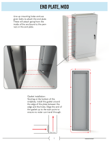
14. Install the Back.
Cement the channels in the back in figure #C-6.
Fig. C-6 Back Place the bottom of the back plate in position and
move the top of the plate inward.

With the back leaning slightly outward, put the back in position on the bottom. Push the top of
the back inward so the studs at the top of the back will pass through slotted tabs on the sides.
Place washers on the studs. Screw hex head nuts onto the studs to secure the back to the
sides. Tighten the bolts holding the inner bottom to the bottom.
15. Install the grates.
Put the rocker grates and fixed grate in position. The tops of the rocker grates should tilt
backward slightly.
The rocker grates should tilt slightly backward Place the front edge of the grate
In position and lower the back edge
16. Install the Grate Frame.
Put the grate frame in plate over the grates. Be sure the tops of the rocker grates tilt backward
a little.
17. Install the Grate Back.
Attach the grate back to the inner back two ¾” hex head cap screws and washers.
Attach the grate back with screws and washers and the balance air plate with screws.
/