Page is loading ...

VLC
1
INSTRUCTION MANUAL
We’ll Make It Stress-Free
If you have any questions along the way, just give us a call.
1-800-359-5520 (UK: 0800-056-2853). We’re ready to help!
Scan for easy install video
http://san.us/1082

2
Para Español ver página 22
Drywall
with steel
studs?
Unsure?
Drywall
with wood
studs?
Solid concrete
or concrete
block?
Call Customer Service: 1-800-359-5520 (UK: 0800-056-2853)
Perfect! Perfect!
CAUTION:
DO NOT install
into drywall alone
Steel stud kit required (not included)
Does your TV
(including accessories)
weigh MORE than?
150 lbs.
(68 kg)
130 lbs.
(59 kg)
For walls
with
steel
studs.
For walls with
wood studs,
solid concrete
or concrete
block.
IMPORTANT SAFETY INSTRUCTIONS – SAVE THESE INSTRUCTIONS – PLEASE READ ENTIRE MANUAL PRIOR TO USE
No
—
Perfect!
Yes
—
This mount is NOT compatible. Visit Sanus.com or call
1-800-359-5520 (UK: 0800-056-2853) to fi nd a compatible mount.
Please read through these instructions completely to be sure you’re comfortable with this easy install process.
Also check your TV owner’s manual to see if there are any special requirements for mounting your TV.
If you do not understand these instructions or have doubts about the safety of the installation, assembly or use
of this product, contact Customer Service at 1-800-359-5520 (UK: 0800-056-2853).
Do you have
all the tools
needed?
Before getting started, let’s make sure this mount is perfect for you!
1
2
3
4
What is your
wall made of?
CAUTION: Avoid potential personal injuries and property damage!
● This product includes directions and hardware for use with wood stud, solid concrete and concrete block walls –
DO NOT install into drywall alone.
● The wall must be capable of supporting fi ve times the weight of the TV and mount combined.
● Do not use this product for any purpose not explicitly specifi ed by manufacturer.
● Manufacturer is not responsible for damage or injury caused by incorrect assembly or use.
Ready to
begin?
Wood Stud Install
Concrete Install
Steel Stud Install
Pencil Screwdriver
Tape
Measure
7/32 in.
(5.5 mm)
Wood
Drill Bit
Electric
Drill
Hammer
1/2 in.
(13 mm)
Socket
Wrench
Drill Bit Drill Bit
3/8 in.
(10 mm)
Concrete
1/2 in.
(13 mm)
Steel

3
15.75
400.0
23.62
600.0
16.97
431.0
15.75
400.0
25.37
644.5
7.00
177.8
.33
8.4
16.00
406.4
24.00
609.6
17.72
450.0
8.00
203.2
8.86
225.0
23.62
600.0
12.00
304.8
11.81
300.0
26.30
668.0
5.55
141.0
9.50
241.3
30.00
762.0
2.68
68.0
2.31
58.8
1" POST INSTALLATION
HEIGHT ADJUSTMENT
11°
11°
TV INTERFACE
WALL PLATE
WALL PLATE OPENING
TOP VIEW - DEPTH
SIDE VIEW - HEIGHT ADJUSTMENT
SWIVEL RANGE
3-D
Dimensions (in. [mm])

M8 x 35mm
M8 x 30mm
M8 x 40mm
M8 x 25mm
M8 x 20mm
M8
22mm
4
NOTE: Not all hardware included will be used.
WARNING: This product contains small items that could be a choking hazard if swallowed. Before starting assembly, verify all parts are
included and undamaged. If any parts are missing or damaged, do not return the damaged item to your dealer; contact Customer Service.
Never use damaged parts!
STEP 1 Parts and Hardware
Supplied Parts and Hardware
TV Bracket
01
x1
TV Screws
Washers
Spacers
02
x4
03
x4
04
x4
05
x4
06
x4
07
x4
08
x4

5
5⁄16 in. x 2 3⁄4 in.
1/4-20 x 1.75
.734 x .312 x .065 in.
For concrete installations ONLY
CAUTION: Do not use in drywall or wood
11
x4
10
x1
12
x4
09
x1
13
x4
Cable
Ties
Anchors (Concrete) UX10x60R
Sanus Stud Finder *
Parts and Hardware for STEP 2
Adjustments
S1
x4
S2
x4
S3
x4
Wall Plate
Lag Bolt
Screw
Washer
Anchor
14
x1
Hex Key
3/16 in.
Hardware for STEP 2C Steel Stud Installation [Steel Stud Anchor Kit is NOT INCLUDED]
Contact Customer Service at 1-800-359-5520 to have the additional hardware shipped directly to you.
1/4-20 Snap Toggle BB
Cable Management
* WARNING: This product contains a magnet.
See PAGE 8 for details.

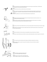
STEP 1 Attach TV Bracket to TV
6
1.1 TV
Screw Length
b: Spacers and longer screws are supplied
to accommodate:
● Extra space needed for cables
● Irregular back TVs
Too Short
Too Long
CAUTION:
Verify adequate
thread engagement with your
screw/washer/spacer combination
AND TV bracket (STEP 1.2).
- Too short will not hold the TV.
- Too long will damage the TV.
If your TV included inset
spacers or wall mount adapters,
see Troubleshooting
on PAGE 21.
Correct
a: Use the shorter screws if you
want your TV closer to the wall,
AND TV bracket
01
sits flat
onto the back of your TV.
TV
TV
a
b
08
0101

7
Position your TV bracket
01
onto your TV and secure using your selection: (a) screw/washer or (b) screw/washer/spacer.
CAUTION: Avoid potential personal injuries and property damage! DO NOT use power tools for this step. Tighten the screws only enough to
secure the TV bracket to the TV. DO NOT overtighten the screws.
IMPORTANT: Ensure TV bracket is securely fastened before moving on to the next step.
Standard configurations are shown. For special applications,
or if you are uncertain about your hardware selection, contact
Customer Service at 1-800-359-5520.
1.2 Attach TV Bracket
08 07
07
a
Flat Back
b
Irregular Back / Extra Space
04 05
02
06
03
Adjust the
straps to
the bottom
of the TV.
UP ARROW
01

8
WARNING:This product contains a magnet. If an implanted medical device such as a pacemaker or implantable cardioverter defibrillator (ICD) is in use, magnetic fields may aect the operation of
those devices, resulting in serious injury or death. If you have an implanted medical device, keep at least 13 cm (5in.) between your device and the magnet. Please consult with your physician or medical
professional prior to using this product.
SANUS
MAGNETIC STUD FINDER
Designed to find your studs and make life easier– included in hardware kit.
TWO SIMPLE STEPS
TO FINDING YOUR STUDS:
Holding it vertically, lightly move the SANUS
Magnetic Stud Finder up and down while
sliding across your wall. The magnet within
will be attracted to the screws in the stud.
Once the magnet has landed on a screw,
place a pencil mark on the wall
directly below the magnet.
You can verify this is a stud by moving the
Magnetic Stud Finder up or down to find
a second or third screw within the wall.
Pull apart the SANUS Magnetic Stud Finder to
expose the probing pin within. Starting about
1
/
2
inch away from the first pencil mark insert
the probing pin into the wall every
1
/
8
inch until
it inserts completely into the wall. Once that
happens, you know you've found one edge of
your stud. Repeat this process till you have
found the stud edges and center of the stud.
Step 1
Step 2
magnet
locates screws in drywall
to show exactly where
your studs are
probing pin
helps find the edges of
your stud within the wall
level
attaches to your wall plate
for hands free leveling
10

9
2
09
CAUTION: Avoid potential personal injuries and property damage!
● Drywall covering the wall must not exceed 5/8 in. (16 mm)
● Minimum wood stud size: common 2 x 4 in. (51 x 102 mm) nominal 1 ½ x 3 ½ in. (38 x 89 mm)
● Minimum horizontal space between fasteners: 16 in. (406 mm)
● Stud centers must be verified – not all walls have conventional 16 in. (406 mm) stud spacing
1. Locate a nail/screw in the studs using the Sanus magnetic stud finder
10
provided. Find the edges of the studs using the probe of the stud
finder
10
. Mark the centers of the studs with a pencil.
2. Level the wall plate
09
and mark the hole locations in the center of the studs.
1
Min. 16 in.
(406 mm)
Max. 5/8 in.
(16 mm)
STEP 2A Attach Wall Plate
Wood Stud Installation
10
10
10

10
3 4
3. Drill pilot holes using a 7/32 in. (5.5 mm) diameter drill bit.
IMPORTANT: Pilot holes must be drilled to a depth of 2 3/4 in. (70 mm). Be sure to drill into the center of the stud.
4. Install the wall plate
09
using four lag bolts
11
. Tighten all lag bolts only until they are pulled firmly against the wall plate.
CAUTION: Avoid potential personal injury or property damage! All four lag bolts
11
MUST BE firmly tightened to prevent unwanted
movement of the wall plate
09
.
Ensure the wall plate is securely fastened to the wall before continuing on to the next step.
Go to STEP 3 on PAGE 16.
11
09
2 3/4 in. (70 mm)
7/32 in.
(5.5 mm)

11
1 2
CAUTION: Avoid potential personal injuries and property damage!
● Mount the wall plate
09
directly onto the concrete surface
● Minimum solid concrete thickness: 8 in. (203 mm)
● Minimum concrete block size: 8 x 8 x 16 in. (203 x 203 x 406 mm)
● Minimum horizontal space between fasteners: 24 in. (610 mm)
● For concrete applications, TV bracket
01
(STEP 3) must remain centered in wall plate
09
. Keep this in mind when selecting the wall plate location.
1. Level the wall plate
09
and mark the hole locations.
2. Drill four pilot holes using a 3/8 in. (10 mm) diameter masonry drill bit. Never drill into the mortar between blocks.
IMPORTANT: Pilot holes must be drilled to a depth of 3 in. (75 mm).
09
3/8 in.
(10 mm)
3 in. (75 mm)
Min. 24 in.
(610 mm)
STEP 2B Attach Wall Plate
Solid Concrete or Concrete Block Installation
10

12
3
4
3. Insert four concrete anchors
12
.
CAUTION: Be sure the anchors
12
are seated flush with the concrete surface.
4. Install the wall plate
09
using four lag bolts
11
. Tighten all lag bolts only until they are pulled firmly against the wall plate
09
.
CAUTION: Avoid potential personal injury or property damage! All four lag bolts
11
MUST BE firmly tightened to prevent unwanted
movement of the wall plate
09
. Ensure the wall plate is securely fastened to the wall before continuing on to the next step.
Go to STEP 3 on PAGE 16.
12
09
11

13
2
CAUTION: Avoid potential personal
injuries and property damage!
● Studs must be at least 2x4 in. / 25 ga.
● Stud type and structural strength
must conform to the North American
Specification for the Design of Cold-Formed
Steel Structural Members
[362 S 125 18, C-Shape, S - Stud Section].
● If back side of wall is unfinished, drywall
must be installed to a minimum of one stud
left and right of the stud(s) being used to
install the mount.
● Drywall must be a minimum of 1/2 in. (13 mm)
thick on each side of the studs, and a
minimum clearance of 1 7/8 in. (48 mm)
behind the wall is required.
● Drywall must be secured to studs with
screws 12 in. (304.8 mm) on center.
● Stud centers must be verified.
09
Min. 16 in.
(406 mm)
Steel Stud Anchor Kit is NOT INCLUDED
Contact Customer Service at 1-800-359-5520 to have
the additional hardware shipped directly to you.
CAUTION: DO NOT use the three
middle slots in the wall plate for mounting.
STEP 2C Attach Wall Plate
Steel Stud Installation
1. Locate the studs using the Sanus magnetic stud finder
10
provided. Find the edges of the
studs using the probe of the stud finder
10
. Mark the centers of the studs with a pencil.
2. Place wall plate
09
at your desired height and position over your studs. Level wall plate
09
and tape in place.
CAUTION: Avoid potential personal injuries and property damage! DO NOT use the
three middle slots in the wall plate for mounting.
1
Min.
1/2 in.
(13 mm)
*

14
3 4 5
1 in.
(25 mm)
1/2 in.
(13 mm)
S1
S1
3. Drill the four pilot holes using a 1/2 in. (13 mm) diameter drill bit.
IMPORTANT: Pilot holes must be drilled to a depth of 1 in. (25 mm). Be sure you drill into the center of the stud.
4. Insert the four anchors
S1
*
into the drilled holes.
5. Pull to rotate the anchor
S1
*
inside the wall.

15
8
09
S2 S3
S1
6 7
S1
6. Hold the end of the anchor
S1
*
, while sliding the cap
P
against the drywall.
7. Snap off the ends of the anchor
S1
*
to lock in place.
CAUTION: Be sure the cap
P
is seated against the drywall surface and the ends of the anchor do not extend beyond the cap
P
- cut if neccessary.
8. Install the four screws
S2
*
and washers
S3
*
and firmly tighten until the washers are pulled flush against the wall plate
09
.
CAUTION: Avoid potential personal injury or property damage! All four screws
S2
*
MUST BE firmly tightened to prevent unwanted
movement of the wall plate
09
. Ensure the wall plate is securely fastened to the wall before continuing on to the next step.
P
P
S1
*
Steel Stud Anchor Kit is NOT INCLUDED
Contact Customer Service at 1-800-359-5520 to have the additional hardware shipped directly to you.

16
Lag bolt
11
STEP 3 Attach TV to Wall Plate
HEAVY! You may need assistance with this step.
1. Hook the TV/bracket
01
onto the wall plate
09
.
2. Rest the TV into place against the wall plate
09
. You will hear an audible click when the TV is securely fastened to the wall plate.
CAUTION: Avoid potential personal injury or property damage! Always make sure your TV bracket
01
is in the locked position so the
TV is securely fastened to the wall plate
09
.
CAUTION: Avoid potential personal injury or property damage!
TV bracket
01
MUST remain
centered in wall plate
09
.
For CONCRETE
applications,
For WOOD STUD and
STEEL STUD applications,
TV bracket
01
MUST be positioned BETWEEN or
OVER the lagbolts
11
on wall plate
09
.
(NOT beyond the four lagbolts
11
).
L
C
01
01
09
09
01
09
Lag bolt
09
01
11
UP ARROW

17
Use the supplied cable ties
13
to secure your cables
in the holes of the TV bracket
01
.
Cable Management
Cables
1 2
13
01
09
01

18
To adjust the height of your TV, turn the level adjustment screw
L
on
the top of BOTH sides of TV bracket
01
to raise or lower the TV.
To level your TV, turn the level adjustment screw
L
on
the top of either side of TV bracket
01
to raise or lower
that respective side of the TV.
TV Adjustments
01
01
14
14
14
LEVEL HEIGHT
L
L
L

19
CAUTION: Avoid potential personal injury or property damage!
CAUTION: Avoid potential personal injury
or property damage!
TV bracket
01
MUST be positioned BETWEEN or OVER the lagbolts
11
on wall plate
09
(NOT BEYOND the four lagbolts
11
).
See CAUTION on PAGE 16.
For Wood Stud and Steel Stud Applications:
Slowly slide TV bracket
01
along the wall plate
09
to reposition.
The wall plate has built-in stops to limit lateral movement.
TV LATERAL SHIFTSWIVEL
TOP VIEW
14
01
For all concrete applications, TV bracket
01
MUST remain centered in wall plate
09
!
To adjust the swivel tension of your TV, turn the swivel
adjustment screw
S
on the top of TV bracket
01
.
S
01 09
Lag bolts
11

20
REMOVING THE TV
09
1 2 3
01
1. Disconnect all cables from the TV.
2. To unlock the TV from the wall plate:
Pull down and hold both release cords
R
while gently pulling the bottom of the TV away from the wall.
CAUTION: Avoid potential personal injury or property damage! To prevent breaking the locking latch: always pull and hold the release cords
R
down while pulling the TV away from the wall.
3. Lift the TV up and off of wall plate
09
.
NOTE: To rehang the TV, follow the procedures in STEP 3 on PAGE 16.
R
HEAVY! You may need assistance with this step.
/