Page is loading ...


Introduction
Disclaimer: Tekno RC is not responsible or liable for any property or personal damage, loss, or
injury incurred as a result of using this product. This kit is meant for use by persons 14 years of
age or older and in the strict connes of a legally permitted RC track or facility.
Warnings: Always double-check that your radio gear is working properly before operating vehicle.
Never operate the vehicle indoors (unless the RC track is an indoor facility). Use caution while
operating vehicle so as not to collide with people who may be turn marshalling or who might
otherwise not be aware that a fast moving RC vehicle is in the vicinity.
Warranty: We warrant that the parts included in this kit are free from defects. If you nd a
defective part in your kit, please contact us @ [email protected] and we will help you to resolve
the issue. We do not warranty parts that may be broken during operation of the vehicle or
otherwise. Refer to the end of this instruction manual for a listing of spare/replacement and
option parts. All spare parts and other info are available on our website (www.teknorc.com)
and through our network of domestic and international dealers and distributors.
Additional equipment and parts needed:
2/3 channel radio transmitter and receiver
1/8th scale ESC and motor
High torque steering servo (240 oz/in torque minimum)
4-6s LiPo battery
1/8th scale buggy tires, wheels & CA glue
Paint for Body
MOD1 Pinion (TKR4171->TKR4190)
Tools needed:
Hex drivers 1.5mm (TKR1104), 2.0mm (TKR1105), 2.5mm (TKR1106)
Nut drivers 5.0mm (TKR1107, 5.5mm (TKR1108), 7.0mm (TKR1109)
17mm Wheel Wrench (TKR1116)
Hobby knife
Needle-nose pliers
Adjustable (Crescent) wrench (for shock assembly)
4mm turnbuckle wrench (TKR1103)
4mm arm reamer
Lexan Body Scissors
Thank you for purchasing the Tekno RC EB48.3 1/8th Scale Electric Competition Buggy Kit. The EB48.3
represents a continued evolution in the 1/8th scale electric class. Since the original EB48 was released
in 2012, we have continued to focus on rening and improving the vehicle to provide superior
performance and value to our customers. We are always working on new projects, so please
check our website (www.teknorc.com) regularly for the latest news, parts, and kits. Thanks again.

Apply grease to the groove
where the o-ring is placed
as well as the o-ring itself
Apply grease to
the groove
where the o-ring
is placed
as well as the
o-ring itself
Apply grease to the groove in the outdrive
Apply grease to the
groove in the outdrive
Fill with 5000 wt oil to
1mm below full
DO NOT OVER FILL
TKR5145B
TKR5144
Bag A
Center Differential
(overview)
TKR5237K
TKR5149
TKR5150
TKR5150
TKR5143
TKR5113
*TKR5237
*TKR5115
(Option)
TKR1325
M3x14mm Flat Head Screw
x4
TKR5144
TKR5145B
TKRBB08165
Ball Bearing(8x16x5mm)
x2
TKR5144
Differential 0-rings
x2
TKR5145B
Differential Shims (6x17mm)
x2
TKR1325 x4
TKR5149
TKRBB08165
Diff
Oil
TKR5112X
TKR5112X
TKR5150
TKR5144
3
Grease
Grease
Grease
Grease
Step
A-2
Step
A-1
Step
A-4
Step
A-3
*TKR5149A
(Option)
*
TKR5149A
(Option)

Apply grease to the groove
where the o-ring is placed
as well as the o-ring itself
Repeat for rear di
Fill FRONT with 5000 wt oil
Fill REAR with 5000 wt oil
to1mm below full
DO NOT OVER FILL
Repeat for rear di
Repeat for rear di
Repeat for rear di
*TKR5149A
(Option)
Apply grease to the groove in the outdrive
TKR5145B
TKR5144
TKRBB08165
Grease
Grease
TKR5149
TKR5150
*
TKR5149A
(Option)
Diff
Oil
Apply grease to
the groove
where the o-ring
is placed
as well as the
o-ring itself
Apply grease to the
groove in the outdrive
Bag B
Front and Rear Differential
(overview)
TKR5151
TKR5149
TKR5150
TKR5150
TKR5143
TKR5113
TKR1325
M3x14mm Flat Head Screw
x8
TKR5144
TKR5145B
TKRBB08165
Ball Bearing(8x16x5mm)
x4
TKR5144
Differential 0-rings
x4
TKR5145B
Differential Shims (6x17mm)
x4
TKR1325 x4
TKR5114X
TKR5114X
TKR5144
4
Grease
Grease
Step
B-2
Step
B-1
Step
B-4
Step
B-3

TKR5075
TKR5012
TKR5152
TKR5012
TKR5268
TKR1222
TKR1222
TKR1525
TKR1222
TKR1525
TKR1222
TKR1226
TKRBB05114
TKR1525
M3x14mm Cap Head Screw
x6
TKR1603
M5x4mm Set Screw
x1
TKR1222
13x16x0.1mm Diff Shim
x2
TKR1226
5x7x0.2mm Shim
x1
TKR1603
TKRBB05114
TKRBB05114
TKR1226
TKRBB05114
TKR1603
TKR1525TKR1525
Grease
Front
Rear
Note: at spot
Note: at spot
Note: The front and rear
bulkheads are dierent.
The front has a much
greater output angle
compared to the rear.
*
may not be needed
*
may not be needed
Bag C
Front Gearbox
(overview)
5
Thread
Lock
Step
C-1
Step
C-2
Step
C-3
Note: TKR1222 and TKR1226 Shims - The gear mesh should be tight without any binding. TKR1226 should
always be installed. Then test tment of the di with both TKR1222 shims on the gear-side of the di. If the di
turns freely without binding, continue to next step. If the di binds and does not turn freely (it will make a
grinding or crunching sound when spun), remove one TKR1222 shim from the gear side and install it onto the
other side of the di. Reassemble and test the mesh again. If it is still binding, remove the second TKR1222 shim
from the gear side and install it onto the other side of the di. When you are satised that you have the best
gear mesh possible continue to the next step. You may end up using only one shim on the gear side.
TKRBB05114
Ball Bearing (5x11x4)
x2

TKR5075
TKR5016B
TKR5152
TKR5016B
TKR5269
TKR1222
TKR1222
TKR1525
TKR1529
TKR1222
TKR1529
TKR5181
TKR1525
TKR1222
TKR1525
TKR1226
TKRBB05134
TKR1525
M3x14mm Cap Head Screw
x4
TKR1603
M5x4mm Set Screw
x1
TKR1222
13x16x0.1mm Diff Shim
x2
TKR1226
5x7x0.2mm Shim
x1
TKR1603
TKRBB05134
TKRBB05134
TKR1226
TKRBB05134
TKR1603
TKR1525TKR1525
Grease
Front
Rear
Note: at spot
Note: at spot
Note: The front and rear
bulkheads are dierent.
The front has a much
greater output angle
compared to the rear.
*
may not be needed
*
may not be needed
TKR1529
M3x20mm Cap Head Screw
x1
Bag D
Rear Gearbox
(overview)
6
Thread
Lock
Step
D-1
Step
D-2
Step
D-3
Note: TKR1222 and TKR1226 Shims - The gear mesh should be tight without any binding. TKR1226 should
always be installed. Then test tment of the di with both TKR1222 shims on the gear-side of the di. If the di
turns freely without binding, continue to next step. If the di binds and does not turn freely (it will make a
grinding or crunching sound when spun), remove one TKR1222 shim from the gear side and install it onto the
other side of the di. Reassemble and test the mesh again. If it is still binding, remove the second TKR1222 shim
from the gear side and install it onto the other side of the di. When you are satised that you have the best
gear mesh possible continue to the next step. You may end up using only one shim on the gear side.
TKRBB05134
Ball Bearing (5x13x4)
x2

TKR1529
TKR1201
TKR1221
TKR1221
TKR1201
TKR1529
TKR1529
M3x20mm Cap Head Screw
x4
TKR1524
M3x12mm Cap Head Screw
x6
TKR1201
M3 Lock Nut Black
x2
TKR1221
M3x8mm Washer
x2
Step
E-1
Step
E-2
TKR1524
TKR1524
TKR5181
Bag E
Low Profile Wing Mount
7
SETTINGS
1 2
3 4
1 2
3 4
POSITION SETTINGS
1 - REARWARD LOW 2 - FOREWARD LOW
3 - REARWARD HIGH 4 - FOREWARD HIGH
DOWNFORCE SET TINGS
(downforce angles)
Note: Stock position setting is
# 4, Rearward High
Note: Stock downforce setting is 4
°
4
°
7
°
10
°

Stock Position
(”D” Block)
Stock Position
(”C” Block)
30.2
TKR1601
TKR1601
TKR1601
TKR5086
TKR5491 - 2.4mm
TKR5086
Install the sway bar ball onto the
sway bar wire until the end of
the wire is ush with the ball as
picture above.
Note: Loosen the M3x4 set screw (TKR1601)
if
the anti-roll bar does not
turn freely.
Note: Do not over-tighten
TKR5049A
TKR5163
TKR5164
TKR5165
TKR5184
TKR5174
TKR1402
TKR1601
TKR5079A
TKR1522
TKR1522
M3x8mm Cap Head Screw
x2
Bag F
Rear End
*TKR5490 - 2.3mm
*TKR5492 - 2.5mm
*TKR5493 - 2.6mm
*TKR5494 - 2.8mm
*TKR5495 - 3.0mm
(Option)
Thread
Lock
Thread
Lock
8
TKR1327
TKR1333
M3x40mm Flat Head Screw
x2
TKR1238
M4x10mm Droop Screw
x2
TKR5049A
Pivot Ball Sway Bar
x2
TKR5079A
Stabilizer Ball
x2
TKR1529
M3x20mm Cap Head Screw
x2
TKR1327
M3x16mm Flat Head Screw
x2
TKR1333TKR1333
TKR1238
TKR1529
TKR1601
M3x4mm Set Screw
x6
Step
F-1
Step
F-2
Step
F-3
TKR5020
TKR1402
M3x8mm Button Head Screw
x4
TKR5165
Note: With these stock
center dot settings,
Anti-Squat = 2° / Rear Toe = 3°
Use a #19 drill bit or
4mm reamer to ream
arms until hinge pin
falls through freely.

TKR5072
TKR5073
TKR5070
TKR5073
TKR5034
TKR5165
TKR1201
TKR1201
TKR1601
TKR5165
TKR5073
CV Joint Pin
x2
TKR1201
M3 Locknut Black
x4
Grease
Step
G-1
Step
G-2
Changes to the wheelbase have a dramatic eect on handling,
since it shifts the disribution of weight over the rear wheels.
This adjusts traction. By shortening the wheelbase at the rear, you
are placing more weight over the rear wheels.
Changes to the wheelbase also change the amount of sweep the
rear driveshaft will have. More driveshaft sweep creates an eect
similar to anti-squat, where the rear end gets pushed upwards on
throttle. This helps reduce chassis slap when landing jumps on throttle.
(FRONT)
(REAR)
TKR1603
M5x4mm Set Screw
x2
TKRBB13194
Ball Bearing (13x19x4)
x2
TKRBB08165
Ball Bearing (8x16x5)
x2
TKR5071X
M3x16.8mm Pin
x2
TKR1601
M3x4mm Set Screw
x4
Bag G
Rear Hub/CVA Assembly
9
Thread
Lock
Note: Notch on pin
needs to line up
with set screw.
TKR5199
TKRBB13194
TKRBB08165
TKR5071X
(Option)
*TKR5071B
*TKR5071C
(Option)
*TKR5199A
TKR1603

TKR5187
TKR5050
TKR5187
TKR5052A
This side mounts on hub
Note: no ange
This side mounts on shock tower
Note: ange
TKR5053A
28.50
Note: notch always goes
on
left side of vehicle
1
2
3
4
5
A
B
C
Stock position is 4/B
TKR1529
TKR1201
Right
TKR5053A
This side mounts on hub
Note: no ange
This side mounts on shock tower
Note: ange
TKR5187
Left
TKR1201
TKR1529
TKR5050
D
TKR1201
M3 Locknut Black
x4
TKR1529
M3x20mm Cap Head Screw
x4
TKR5053A
Pivot Ball M3x6.8mm
No Flange
x2
TKR5052A
Pivot Ball M3x6.8mm
x2
TKR5187
TKR5052A
Step
G-3
Step
G-4
Bag G
Rear Camber Links
10

Use a #19 drill bit or
4mm reamer to ream
arms until hinge pin
falls through freely.
Stock Position
(”B” Block)
Stock Position
(”A” Block)
30.2
TKR1601
TKR1601
TKR1601
TKR5086
TKR5082 - 2.4mm
TKR5086
Install the sway bar ball onto the
sway bar wire until the end of
the wire is ush with the ball as
picture above.
Loosen the M3x4 set screw
(TKR1601) if
the anti-roll bar
does not
turn freely.
Note: Do not over-tighten
TKR1601
TKR1522
TKR1522
TKR1522
M3x8mm Cap Head Screw
x2
Bag H
Front End
*TKR5080 - 2.2mm
*TKR5081 - 2.3mm
*TKR5083 - 2.5mm
*TKR5084 - 2.6mm
*TKR5085 - 2.8mm
*TKR5087 - 3.0mm
(Option)
Thread
Lock
Thread
Lock
11
TKR1327
TKR1333
M3x40mm Flat Head Screw
x2
TKR1238
M4x10mm Droop Screw
x2
TKR5049A
Pivot Ball Sway Bar
x2
TKR5079A
Stabilizer Ball
x2
TKR1529
M3x20mm Cap Head Screw
x2
TKR1327
M3x16mm Flat Head Screw
x2
TKR1333
TKR1529
TKR1238
TKR5020
TKR1601
M3x4mm Set Screw
x6
Step
H-1
Step
H-2
Step
H-3
TKR5162
TKR5161
TKR5286
TKR5165
TKR5149A
TKR5165
TKR5165
Note: With these stock settings,
Kick Up = 8.5° / Arm Sweep = 0°
For reference, with center dot
inserts in both braces,
Kick Up = 10° / Arm Sweep = 0°

TKR5072
TKR5193
TKR5054A
TKR1445
TKRBB08165
TKR5194
TKR5070
TKR1447
TKR1447
TKR1601
TKR1601
TKR1601
TKRBB13194
TKR1221
TKR1401
TKR1445
TKR5054A
Spindle Pin Sleeve
x4
TKR5055A
Suspension Pin Sleeve
x4
Grease
TKR5073
TKR5073
Step
I-1
Step
I-3
Step
I-2
Thread
Lock
TKR5071X
TKR1603
(Option)
*TKR5071B
*TKR5071C
TKR1445
M4x14mm Button Head Screw
x4
TKR1447
M4x16mm Button Head Screw
x4
TKR5073
CV Joint Pin
x2
TKR1603
M5x4mm Set Screw
x2
TKRBB13194
Ball Bearing (13x19x4)
x2
TKRBB08165
Ball Bearing (8x16x5)
x2
TKR5071X
M3x16.8mm Pin
x2
TKR1601
M3x4mm Set Screw
x8
TKR5055A
Note: The steering stops provide adjustable
travel limiters that you can adjust to your
driving style. For very tight tracks you may
want to experiment with less limiting washers
(more steering travel). However, with too
much steering travel the rear end can lose
traction more easily coming out of corners.
After months of testing on dierent track
surfaces, 3 washers is the best starting point.
TKR1401
M3x6mm Button Head Screw
x2
Bag I
Front Spindle / CVA Assembly
12
Note: notch on pin
needs to line up
with set screw.
TKR1221
M3x8mm Washer
x8

TKR1529
Stock position is 1/B
TKR1201
TKR1201
TKR1529
24.00
TKR1201
M3 Lock Nut Black
x4
TKR1529
M3x20mm Cap Head Screw
x4
TKR5052A
Pivot Ball M3x6.8mm
x2
TKR5053A
Pivot Ball M3x6.8mm
No Flange
x2
TKR5187
TKR5050
TKR5187
TKR5052A
TKR5053A
Right
TKR5187
This side
mounts on hub
Note: no ange
This side
mounts on hub
Note: no ange
This side mounts
on shock tower
Note: ange
This side mounts
on shock tower
Note: ange
TKR5187
Left
TKR5050
TKR5053A
TKR5052A
Note: Notch always goes
on
left side of vehicle
1
2
3
4
5
6
A
B
Step
I-4
Step
I-3
Bag I
Front Camber Links
13

TKR1323
TKRBB050825
TKRBB050825
Note: Apply
a small drop
of oil for
easy o-ring
installation.
Note: Tighten nut all the way down,
then back it o 3 full turns
Stock Position
(is MIDDLE hole)
TKR5100
TKR5056
TKR5123
TKR5052A
TKR5104
TKR5104
TKR5101X
TKR5231
TKR1201
TKRBB06103
TKRBB06103
TKR1529
Note: Stock bumpsteer setting is
4 washers
under the steering ball link.
4 x TKR1221
TKR1221
TKRBB06103
TKRBB050825
TKR5104
TKR5122
TKR1529
TKR1221
TKR5103
TKR5103
TKR1201
TKRBB06103
TKR5052A
31.00
TKR1323
M3x10mm Flat Head Screw
x2
TKR1201
M3 Lock Nut Black
x2
O-ring 16x12x2
TKR5231
x1
TKRBB06103
Ball Bearing (6x10x3)
x4
TKRBB050825
Ball Bearing (5x8x2.5)
x4
TKR1529
M3x20mm Cap Head Screw
x2
TKR5052A
Pivot Ball M3x6.8mm
x4
TKR1221
M3x8mm Washer
x8
TKR5052A
TKR5052A
TKR5052A
Thread
Lock
Thread
Lock
Thread
Lock
Right
Left
Step
J-1
Step
J-2
Step
J-3
Step
J-4
Bag J
Steering Assembly
(overview)
14
Note: Notch always goes
on
left side of vehicle

TKR5107
TKR1323
TKR1201
TKR1443
TKR5102A
TKR1443
Note: On steps K-2, K-3 and K-4 Do not
tighten the
screws all the way down until
the assembly steps are complete. Position
the entire front assembly on the chassis
and tighten each screw evenly.
TKR1522
TKR5166
TKR1443
TKR1344
TKR1344
TKR1343
TKR5062
Note: Inititial bumpsteer setting
is four
washers above the steering ball link.
TKR5181
TKR1522
M3x8mm Cap Head Screw
x1
TKR1343
M4x10mm Flat Head Screw
x2
TKR1344
M4x12mm Flat Head Screw
x6
TKR1201
M3 Lock Nut Black
x2
TKR1323
M3x10mm Flat Head Screw
x1
TKR1443
M4x10mm Button Head Screw
x5
TKR1529
M3x20mm Cap Head Screw
x2
TKR1221
M3x8mm Washer
x8
Note Step K-2:
Line up the bottom of the
steering posts (TKR5102A)
with the corresponding
recessed cut in the
chassis
.
Thread
Lock
Thread
Lock
Step
K-3
Step
K-4
Step
K-1
Step
K-2
Bag K
Front End Assembly
15

TKR5107
TKR5260
TKR5263
TKR1522
TKR5191
TKR1443
TKR5062
TKR1344
TKR1343 x5
TKR1443
TKR5062
TKR5076
TKR1344 x5
TKR1524
TKR5263
*TKR5262
(option)
TKR1522
M3x8mm Cap Head Screw
x2
TKR1524
M3x12mm Cap Head Screw
x4
TKR1343
M4x10mm Flat Head Screw
x5
TKR1443
M4x10mm Button Head Screw
x2
TKR1344
M4x12mm Flat Head Screw
x7
Thread
Lock
Thread
Lock
Step
L-1
Step
L-3
Step
L-2
Step
L-4
Bag L
Center/Rear
Assembly
16

17
Shock Filling Instructions
For both front and rear shocks
The following steps and information will provide you with the best way to ll and bleed your
shocks. After thorough testing, we've found it's easiest to complete steps 1 through 3 on each
shock before moving onto step 4. By the time you've nished step 3 on the last shock the rst
one will be ready for step 4.
Standard or Vented Cap Build:
Step 1: Extend the shock shaft all the way down. Fill the shock with oil until the it is about 90% full.
Step 2: Slowly pump the shock shaft up and down 3-5 times to release air bubbles from underneath
the piston.
Step 3: Let the shock rest vertically with the shock shaft fully extended for ve minutes or until all
the air bubbles have released.
Step 4: Next you will top o the shock with oil, to about 1-2mm below the top edge.
(If you do overll the shock, it won’t hurt performance, it will just spill out and make a little bit of a
mess. If you underll the shock, it will cause air to be trapped inside.)
Step 5: Place the bladder INSIDE the shock cap and put a few drops of oil on the bladder.
Step 6: Put a paper towel down below the build to catch drips and have another ready to
wipe o excess oil. Place the cap on the shock and screw down about half way. Lay the shock
over about 45 degrees with the bleeder hole facing up.
Step 6A: (Standard non-vented) Push the shaft in for the amount of rebound desired.
Step 6B: (Vented “Stock”) Push the shaft in until about 15mm of shaft is showing.
• Make sure that you match the rebound amount between the left and right shocks.
• Oil should be oozing out of the bleeder hole.
Step 7: Hold the cap rmly in place with the bleeder hole facing up and turn the shock body until
hand tight. The shock will continue to ooze oil.
Step 8: Fully tighten down each shock with shock tools until cap is secure and wipe excess oil away.
Emulsion Build:
Prep your shock caps TKR6018 (optional for EB48) accordingly by drilling out the large angled
bleeder hole in the top of the cap. Place the larger thin o-ring around the base of the threads
where the shock cap screws on (see diagram on the next page). This seal is crucial to the build.
Follow steps 1-4 above.
Step 5: Rebound is more of a natural side eect of an emulsion shock. It’s not something that can
be set accurately because you run the risk of hydrolocking the shock if you do not push the shaft
all the way in when you bleed it. For now leave the shaft fully extended.
Step 6: Fill the shock up, over lling just slightly without spilling to create a small dome of oil.
Step 7: Place a little bit of oil in the shock cap and quickly put the shock cap on the shock body.
Tighten the cap all the way down. Very slowly push the shaft in. Oil will start to bleed out of the top
of the cap. While wiping away excess oil, continue to slowly push the shaft in ALL THE WAY.
If no oil comes out when the shaft is fully inserted, you will need to start over at step 6.
Step 8: Install the TKR1341 M4x6mm at head screw and TKR5125 black o-ring to seal
the cap (see diagram). Tighten until o-ring is fully seated.

TKR6048
TKR6140
TKR1240
TKR1202
Note: Slot in spring
perch should face
outside of vehicle.
Note: Black screw
is CW threaded
and goes on
driver side.
Silver screw is
CCW and goes
on passenger side.
TKR1605
TKR6015
TKR6008
TKR6009
TKR6016
M2.5 Lock Nut Zinc
TKR1200
x2
TKR1240
M3x18mm Shock Mnt Screw
x2
TKR1211
M3 Lock Nut Flange Black
x2
*TKR6046
*TKR6047
*TKR6035
*TKR6036
*TKR6037
*TKR6038
*TKR6039
(Option)
TKR1200
TKR6159 (conical)
(tapered)
TKR6017
TKR5049A
*TKR6017T
(Option)
*TKR6155
*TKR6156
*TKR6157
*TKR6158
*TKR6160
(Option)
*TKR6050
*TKR6051
*TKR6052
*TKR6053
*TKR6054
*TKR6063
*TKR6064
*TKR6065
(Option)
Note:
Shaft guide
orientation
Note:
Front shocks use
shorter shock bodies -
TKR6016,
shorter shock shafts -
TKR6017,
shorter springs -
TKR6048
and shorter shock boots -
TKR6144
Note: Use green
slime or oil on
shock shaft
threads AND
O-rings to
prevent tearing
and leaking.
Step
M-1
Step
M-2
Step
M-3
TKR6140
TKR6144
Note: Shock boots
must be installed
before attaching
rod end.
TKR1202
M4 Lock Nut Black
x2
TKR1211
TKR6007
TKR5027
Note: Tighten TKR1211 lock nut all the way down, then back o 1/4 turn. Use thread lock!
Thread
Lock
TKR6003
TKR6009
TKR6013
*TKR6018
*TKR6003B
(Option)
Fill oil level just
below the
top of
the shock body.
Use #400wt Oil
Front
Note: Apply a small
drop of oil for
easy installation.
400
Bag M
Front Shock Assembly
18
Stock shock position is outside
hole on the arm and 2nd from
inside hole on the tower
Stock front ride height is 27mm
Shock length (droop) is 120mm
TKR1605
M3x10mm Set Screw
x2
Note:
Make sure to tighten both cartridge cap
(TKR6015) and shock cap (TKR6003) to ensure
a proper seal. Tools may be required.

TKR6033
TKR6140
TKR6007
TKR5027
Note: Slot in spring
perch should face
outside of vehicle.
TKR1202
TKR1605
TKR6015
TKR6008
TKR6009
TKR6060
M2.5 Lock Nut Zinc
TKR1200
x2
TKR1211
M3 Lock Nut Flange Black
x2
*TKR6041
*TKR6042
*TKR6043
*TKR6030
*TKR6031
*TKR6032
*TKR6034
*TKR6055
*TKR6056
(Option)
TKR6061
TKR5049A
*TKR6061T
(Option)
Note:
Shaft guide
orientation
Note:
Rear shocks use
longer shock bodies -
TKR6060,
longer shock shafts -
TKR6061,
longer springs -
TKR6033
and longer shock boots -
TKR6145
Note: Use green
slime or oil on
shock shaft
threads AND
O-rings to
prevent tearing
and leaking.
Step
N-1
Step
N-2
Step
N-3
TKR6140
TKR6145
Note: Shock boots
must be installed
before attaching
rod end.
TKR1202
M4 Lock Nut Black
x2
TKR1211
Note: Tighten
TKR1211 lock
nut all the way
down, then back
o 1/4 turn.
Use thread lock!
Thread
Lock
TKR6003
TKR6009
TKR6013
*TKR6018
*TKR6003B
(Option)
Fill oil level just
below the
top of
the shock body.
Use #450wt Oil
Rear
Note: Apply a small
drop of oil for
easy installation.
TKR1240
Note: Black screw is CW threaded and goes on passenger side.
Silver screw is CCW and goes on driver side.
TKR1240
M3x18mm Shock Mnt Screw
x2
450
TKR1200
TKR6159 (conical)
(tapered)
*TKR6155
*TKR6156
*TKR6157
*TKR6158
*TKR6160
(Option)
*TKR6050
*TKR6051
*TKR6052
*TKR6053
*TKR6054
*TKR6063
*TKR6064
*TKR6065
(Option)
Bag N
Rear Shock Assembly
19
Stock shock position is inside
hole on the arm and 2nd from
inside hole on the tower
Stock rear ride height is 29mm
Shock length (droop) is 135mm
TKR1605
M3x10mm Set Screw
x2
Note:
Make sure to tighten both cartridge cap
(TKR6015) and shock cap (TKR6003) to ensure
a proper seal. Tools may be required.

TKR5060
TKR5065
Steering servo (not included)
TKR1525
ESC (not included)
double sided tape
TKR5065
TKR5125
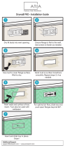
Note: Install ESC tray on the
mudguard (do not overtighten)
.
Note: CA glue 3 black o-rings (TKR5125) to the bottom legs of the ESC tray.
TKR1401
TKR1322
TKR1525TKR1525
TKR5065
TKR5065
TKR5065
TKR1401
TKR1322
TKR1322
TKR1401
RX (not included)
Transponder (not included)
TKR1401
M3x6mm Button Head Screw
x6
TKR1322
M3x8mm Flat Head Screw
x5
TKR1525
M3x14mm Cap Head Screw
x6
TKR5125
O-ring 3x7mm
x3
TKR1221
M3X8mm Washer
x4
TKR1221
TKR1221
Note: Feed the servo wire underneath the esc tray
in between the mounting screws on the mud guard,
then feed both ESC and servo wires into the RX
box as shown. I
nstall wire retainers (TKR5065)
to secure them properly.
CA
glue
Step
O-4
Step
O-3
Step
O-1
Step
O-2
Bag O
Final Assembly
20
*TKR5060C
(Option)
Note: we recommend
using a servo with at
least 300 oz/in torque.
/