Page is loading ...

Refer to
Selective Unlocking
Options on Pg4
& See note 1.5
See Note 7.0
& Table 1 (7.4)
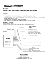
SELECTIVE UNLOCKING
THESE OUTPUTS BELOW ARE NEGATIVE SWITCHING (MAXIMUM CURRENT 300mA)
To ground or +12V
as required
Not connected
+12V
Common
Coil
Coil
N.Closed
N.Open
TO TRUNK RELEASE SOLENOID
(PFK SOLENOID PART NO. 088-510)
TRUNK RELEASE
RELAY
30 85 86 87a 87
NOT SUPPLIED - G.P. RELAY
Part No. 436-900
INTERIOR LIGHT
See Note 10.0
and Table1 (8.3)
Drives interior light
See Note 10.0 & Table1 (8.3)
DRIVER'S
DOOR
SWITCH
DOORS
+ 12 V
Common
Coil
Coil
N.Closed
N.Open
+12V
+12V
Connect to
“BLUE" Door wire
RELAY REQUIRED FOR POSITIVE
INTERIOR LIGHT.
WITH POSITIVE DOOR SWITCHING
INTERIOR LIGHT WILL NOT FADE
ON AND OFF
INTERIOR
LIGHT
See Note 10.0
Not
connected
RELAY
30 85 86 87a 87
+ 12 V
G.P. RELAY Part No. 436-900
(NOT SUPPLIED)
PIN 21
PIN 1
PIN 8
PIN 5
PIN
16
TRUNK RELEASE
POSITIVE PULSE
BLACK/YELLOW WIRE
TRUNK RELEASE
BOOT
DOORS
POS DOORS
NEG
OUT
SPEAKER
OUTPUT
RED
BLACK
NEG BONNET
BATTERY BACK UP SIREN
BONNET
BLACK
SIREN
+ 12 V
See Note
9.0
PAGE
1 OF 5
DPFK 695/522
REAR VIEW OF
24-WAY HARNESS
1.
2.
3.
4.
5.
6.
7.
8.
9.
10.
11.
12.
13.
14.
15.
16.
17.
18.
19.
20.
21.
22.
23.
24.
Negative Doors + Dome Light driving
Can High
Can Low
Aux 2 (Windows/Pager) (White/Black wire)
Aux 3 (Trunk release) (Black/Yellow wire)
Not Used
Neg. Bonnet
Positive Doors
Service
Ground
+ 12V
Speaker / Siren / Horn
Unlock - Common (Blue wire)
Unlock - N/O (Grey wire)
Unlock - N/C (Yellow wire)
Aux 1 (Selective Unlock / Neg. Out when armed)
Ignition
Indicators
Indicator +12V
Indicators
Negative Boot
Lock - Common (Green wire)
Lock - N/O (Brown wire)
Lock - N/C (Violet wire)
ANTENNA
Do not sleeve or tape
antenna with other wires.
Run antenna separately
and try to position
away from metallic
objects
CAN programming connection.
Refer to programming
instructions.
CHASSIS
CHASSIS
+ 12 VOLTS
+ 12 VOLTS
GROUND
WIRE HARNESS INTO THE VEHICLE PRIOR
TO PLUGGING CONTROL MODULE IN
LED
CAN STATUS
PIN 2
PIN 3
PIN 10
PIN 11
PIN 7
PIN 12
PIN 19
PIN 13
PIN 22
PIN 9
PIN 18
PIN 20
PIN 4
PIN 15
PIN 24
PIN 14
PIN 23
PIN 17
CAN HIGH
CAN LOW
}
}
SLEEVED WITH
WIRES FROM
PIN 22, 23 & 24
SLEEVED WITH
WIRES FROM
PIN 13, 14 & 15
FUSE
+12V
NOTE : FUSES ARE
NOT SUPPLIED
+12V WHEN THE IGNITION IS
IN THE ON AND CRANK POSITION.
IGNITION (FUSED)
INDICATOR
+ 12 VOLTS
IGNITION
BOOT
+12V
Ignition
switch
GROMMET
INTERNAL RELAY CONFIGURATION
+12V
UNLOCK RELAY
LOCK RELAY
N.O. - GREY
N.O. - BROWN
N.C. - YELLOW
N.C. - VIOLET
COMMON - BLUE
COMMON - GREEN
SLEEVED
Hazard Pulse
See Note 11.0
& Table 1 (8,9)
JOIN TO THE
POSITIVE WIRE
OF INDICATOR
LIGHTS
+ +
LEFT
RIGHT
INDICATORS
INDICATORS
(UNDER CARPET SWITCH) USED FOR VALET MODE
AND ADDITIONAL FEATURES (SEE 4.0, 13.0 & 14.0)
BLACK
BLACK/GREY
SERVICE
REAR VIEW OF UNIT
Can be connected to Pager Module/Tracking System.
To select this function see note 4.0 & Table 1 (5.1)
Requires additional Window Closer Module
(PFK Part No. 210-000)
To select this function see 4.0
& Table 1. (5.1, 5.2, 5.3 & 5.4)
THE OUTPUT BELOW IS NEGATIVE
SWITCHING (MAXIMUM CURRENT 300mA)
OR
OR
OR
WINDOWS
PAGER/TRACKING
OR
OR
WHITE/
BLACK
WHITE/
BLACK
Wiring information will be supplied with the Module
}
}
}
REFER TO “VEHICLE SPECIFIC INFORMATION” FOR REQUIRED WIRING
MANDATORY WIRING
To other side
of circuit to be
immobilised
Not Connected
To one side of circuit
to be immobilised
Connect to neg out
when armed.
GP RELAY
PFK PART NO.436 900
87
87a
86
85
30
To ignition
NEG OUT WHEN ARMED
To select & adjust this Function
see Note 4.0 & Table 1
(4.1, 4.2, 4.3 & 4.4)".
To select this function
see Note 4.0 & Table 1 (4,4)
AUTOWATCH 446 RLC ALARM WIRING DIAGRAM
REV. 2
01/04/09

PAGE
2 OF 5
NOTE : TO FULLY UNDERSTAND THE OPERATION OF THE 446 RLC, YOU MUST
GO THROUGH THIS DOCUMENT IN CONJUNCTION WITH THE OWNERS
MANUAL SUPPLIED WITH THE PRODUCT.
MECHANICAL INSTALLATION
MOUNTING
The control module must be installed in a concealed location inside the vehicle. Do not
plug in the control module until the wiring is complete. All wire joints must be soldered
and well insulated. Mount the control module vertically with the wires exiting from the
bottom to prevent damage resulting from water leaking into the vehicle and into the unit.
WIRE HARNESS
INTO THE VEHICLE
PRIOR TO PLUGGING
CONTROL MODULE IN
ALARM STATUS LED
MOUNT FOR MAXIMUM VISIBILITY.
Part No. 198-954
NOTE : THE STATUS LED MUST BE CONNECTED WITH THE SENSOR SHOWN.
Split-eye Ultrasonic Sensor
Microwave Sensor
Part No. 362-000 (Digital
with Automatic Gain Control
ie. no adjustment)
Part No. 567-000
BLACK
OR
RED
S
PL
IT
E
YE
-
T
R O
NI
C
U
L
AS
RE
D
B
KL
44
See Note : 2.0
SENSORS
OVERVIEW
WIRING
NOTE : DO NOT REMOVE WIRE LABELS UNTIL THE INSTALLATION IS
TESTED AND WORKING.
GROUND/CHASSIS
Connect the wires marked "Ground" to two independent earth points.
CENTRAL LOCKING
The 446 has two relays for full central locking (see page 3) and low current
negative central locking on the brown and white wires (see page 1). The time
can be extended from 0.3 seconds to 3.0 seconds if required. See table 1. If
your vehicle supports locking on CANBus, either setting may be selected.
SELECTIVE UNLOCKING SEE 4.0 & TABLE 1
Two methods of selective unlocking are available. Program option 123 41.
Type 1 is suited to aftermarket installations where central locking motors
are retrofitted to the vehicle. This option isolates the passenger motors by
interrupting the high current wire to the motor while the drivers door unlocks.
Program option 123 42. Type 2 is
suited to OEM central locking configurations. With this system the unlock
pulse unlocks the drivers door only, and the selective unlock pulse unlocks
the other doors.
MOVEMENT SENSOR (Split-Eye Sensor Part Number 362 000)
The ultrasonic can be mounted on opposite sides of the vehicle. The
sensors must face into the vehicle and be firmly mounted in place with no
obstructions immediately in front of them. Note that the two ultrasonic
transducers are not the same. When plugging the sensors into the split-eye
interface unit ensure that the red sleeved sensor is plugged into the two way
connector which is marked “RED” on the housing and the black sleeved
sensor into the connector which is marked “BLACK” on the housing.
Mount the ultrasonic control module and secure the separate sensor cables
to the main loom to prevent accidental unplugging of the sensors.
Note : The split-eye ultrasonic sensor may be optionally replaced by a
microwave sensor (Part No. 267-000) for vehicles with soft tops.
EARLY WARNING (SEE 4.0 & TABLE 1)
To select early warning refer to the programming procedure and enter the
code 123 77. See 4.0 & Table 1
Note: To include an early warning sensor you will require the 2 to 1
special adapter harness (PFK Part No 446-450).
The 446 has been designed to read and write to the vehicle’s CANBus,
allowing some, if not all wiring besides CANH, CANL, +12V and GND to be
left unwired. This is dependent on your vehicle and its specific CANBus
functionality. Kindly consult the “Vehicle Specific Information” to determine
what additional wiring is required for your installation.
The following functionality is available on the 446 RLC:
INPUTS OUTPUTS
Ignition Lock
Doors Unlock
Boot Selective Unlock
Bonnet Trunk Release
ARM from OE Remote Window Closure
DISARM from OE Remote Horn
TRUNK RELEASE alarm isolation from OE Remote Hazards
*Functions which are not CAN enabled on your vehicle are required to
be hardwired.
MANDATORY WIRING:
CANH / CANL
Connect the wire marled “CANH” to the CANH of your vehicle and the wire
marked “CANL” to the CANL or alternately to the GROUND of your vehicle in
1-wire CAN vehicles. Be sure to limit the length of each wire to < 30cm.
+12V
Connect the wire marked “+12V” supply line to a fused +12V.
VEHICLE SPECIFIC WIRING
If your vehicle supports selective unlocking on CANBus, Selective
Unlocking, Type 1 MUST be selected.
0.0
1.0
1.1
1.2
1.3
1.4
1.5
2.0
2.1
3.0
3.1
3.1.1
FIRST TIME INSTALL
– ENSURING YOUR CAN VEHICLE IS LEARNT IN
The 446 is supplied with the latest set of supported vehicles pre-installed.
The alarm has been successfully configured when 4 flashes are observed.
When the alarm in learnt into a new vehicle for the first time, the vehicle that
was detected is displayed on the CAN STATUS LED in the manner
described in 3.12.
If the 446 is married to a particular vehicle, after a timed period of no CAN
activity, the unit will enter a low current sleep mode. In this mode, the CAN
STATUS LED remains permanently OFF. Any CAN or alarm activity will
wake up the unit and prompt the currently married vehicle to be displayed
on the CAN STATUS LED (as per 3.12). Following this, the 446 will then
begin to flashing 4 times, indicating the alarm's learnt and ready state.
Part Number 691-000)
(Consult your distributer or Autowatch Portal for details). The learn process
is simple. Plug in the alarm and turn ON the ignition key. In normal
operation the CAN LED on the back of the unit provides details as to the
current state of your unit.
The latest update of supported vehicles may be uploaded into your 446
using the CANBus programming cable ( and
software GUI. All software, software guides and vehicle updates are
available on the Autowatch Portal.
STATE: CAN LED:
Awaiting CAN activity Single Flash
[200ms ON ; 200ms OFF] every 800ms
Vehicle BAUD rate detected Double Flash
Searching for Vehicle 2x [200ms ON 200ms OFF] every
800ms
Vehicle Detection Disabled 2x [200m/600ms* ON 200ms OFF]
every 800ms
Alarm Ready Four flashes
Vehicle Self-Identified 4x[200ms ON 200ms OFF] every
800ms
Vehicle Forced Married 4x[200ms/600ms* ON 200ms OFF]
every 800ms
Serial Flash Empty Five flashes
5x [200ms ON ; 200ms OFF] every
800ms
*The CAN LED alternates between 200ms and 600ms for ON cycles. *
Vehicle Detection is disabled immediately after a Forced Unmarry (See
Note 3.1) and will remain disabled until the power is removed and re-
applied.
CANBus SPECIFIC FUNCTIONALITY (See 4.0 and Table 1)
There may be cases where the unit is incorrectly identified or not identified
at all using the Automatic Vehicle Detection. In this case you may have little
or incomplete CAN functionality for your vehicle. In these cases the
additional abilities are provided: Refer to 4.0 on how to enter the
programmable features.
FORCED MARRY (See 4.0 and Table 1 note 9,3)
Post selecting this feature, the user to required to input 4 additional digits
[a,b,c,d] to represent the vehicle in the same manner as the feature
selection was entered.
These digits represent:
a: Manufacturer ID (Tens)
b: Manufacturer (Units)
c: Model ID (Tens)
d: Model ID (Units)
Eg. The Mercedes Vito VSI shows this car to have a Vehicle ID Reference
of 21-06. In this case a=2,b=1,c=0 and d=6. Note that a 0 is represented by
10 flashes.
The list of Manufacturer and Model ID’s can be found on the Autowatch
Portal and are additionally stated on each Vehicle Specific Information
sheet (VSI). This feature can be selected while the unit is in any state (ie if
the BAUD has not been detected, or if the unit has already been learnt into
another vehicle).
If the vehicle is “found”, the vehicle selected will be displayed on the CAN
Status LED in the menu described in 3.12. If the vehicle is not found, the
CAN Status LED flash rate will remain unchanged.
AUTOWATCH 446 RLC ALARM WIRING DIAGRAM
DPFK 695/522
REV. 2
01/04/09

PAGE
3 OF 5
REV. 2
01/04/09
446 RLC FEATURE SELECTION TABLE
ON
120 seconds
OFF
OFF
OFF
8,1
8,2
8,1
OPTION
FEATURE
Trigger Report back (See 5.0)
Unlock with Ignition
Lock with Ignition
Enter the program code 1,2,3 followed by the Feature Selection Code
NOTE : A ZERO IS REPRESENTED BY TEN FLASHES
FEATURE
SELECTION
CODE
INDICATION
ONE BEEP
OFF
OFF
ON
ON
LED FLASHES
RAPIDLY - 2 SECS
SWITCH IGNITION
OFF TO CLEAR
TWO BEEPS
1,1
3,3
3,4
*
*
1,1
3,3
3,4
Window / Pager (See 6.0)
Interior / Dome Light
Auto rearm time
Arm/disarm Hazard Confirmation
with Autowatch Remote
Arm/disarm Hazard Confirmation
with OE Remote
5,2
5,3
6,1 Arm/disarm tones on/off
5,4
Double Unlock Pulse (See 1.5)
Selective Unlock - Type 1 (See 1.5)
Window 10 second wind time
Double Lock Pulse (See 1.5)
Selective Unlock - Type 2 (See 1.5)
Window 45 second wind time
Selective Unlock Inhibit (See 1.5)
Window 120 second wind time
Selective Unlock / Neg. Out when armed
Auto Arming alarm (See 8.0)
Auto Rearming alarm (See 8.0)
Lock when Auto Arming or Auto Rearming
Early Warning (See 2.1)
Pos Doors/Trunk Isolation Input (See 7.0)
Central locking time 0.3/3.0 sec
Reset (Revert to Factory Setting)
*
TABLE 1
8,8
8,9
9,3
9,4
9,5
Door open audible warning
Hazard Pulse
Vehicle Forced Marriage
Display Current Vehicle
Unmarry & Disable Vehicle Detection
OFF
OFF
OFF
OFF
OFF
OFF
OFF
OFF
OFF
Neg. Out
ON
ON
ON
ON
ON
ON
ON
ON
ON
Selective
WINDOWPAGER
5,1
ON
ON
30 seconds
*
*
*
*
*
*
*
*
*
*
*
3,6
4,1
5,2
3,7
4,2
5,3
6,1
4,3
5,4
4,4
0.3 sec 3.0 sec
LED FLASHES
RAPIDLY FOR
2 SECONDS
9,9
0,4
OFF
OFF
Positive Doors
ON
ON
Trunk Isolation Input
7,7
7,8
7,4
OFFON
OFF
OFF
ON
ON
*
*
*
*
*
*
*
*
*
*
*
*
*
8,7
8,5
8,6
8,3
8,4
OFF
OFF
N/A
N/A
N/A
ON
ON
N/A
N/A
N/A
8,8
8,9
9,3,a,b,c,d
9,4
3,6
4,1
5,1
3,7
4,2
4,3
4,4
7,7
7,8
7,4
8,3
8,2
8,4
8,5
8,6
8,7
9,9
0,4
A. If Neg. Out when Armed is not used: (See wiring diagram for explanation)
B. If Pager is not used, the following window options may be selected:
C. CANBus Specific functionality #
FACTORY SETTINGS HIGHLIGHTED WITH A IN THE TABLE ABOVE.
*
#Note too that depending on your vehicle, Feature Selections 9,3 ; 9,4 ; 9,5 may not be reliable using the
ignition switch and it is thus strongly suggested to use the grey wired valet mode button as the input
method for these selections.
# Note that whilst the ALARM STATUS LED is used to select the digits for feature selections 9,3 ; 9,4 ;
9,5, it is the CAN STATUS LED which returns the Flashing Sequence to identify the vehicle.
3.1.2
3.1.3
3.1.4
4.0
TRIGGER REPORT BACK (SEE 4.0 & TABLE 1 note 1.1)
In the event of a false alarm complaint from a customer, the cause can be
accessed using the Trigger Report Back feature. To access this information,
enter the program code, 1,2,3, followed by the code 1,1. The Alarm Status
LED begins to flash a number of times to indicate the cause of the alarm.
These flashes are as follows:
1 Flash : Movement Sensor (Ultrasonic)
2 Flashes : Wireless Sensor Zone
(When allocated to its own zone)
3 Flashes : Panic
4 Flashes : Ignition
5 Flashes : Negative Door
6 Flashes : Positive Door
7 Flashes : Boot
8 Flashes : Bonnet
The trigger information is cleared once the alarm has been turned on and off
10 times without triggering.
WINDOW PAGER & TRACKING OUTPUT. (SEE 4.0 & TABLE 1 note 5.1)
AUTO ARMING/AUTO REARMING (SEE 3.0 & TABLE 1 note 8.5, 8.6 & 8.7)
Pager & Tracking output : The output is a low current output that can be
connected to a
POS DOORS / TRUNK RELEASE INPUT (SEE 4.0 & TABLE 1 note 7,4)
The Pos Doors input may alternately be enabled as a Trunk Isolation input.
When enabled, a positive pulse on this wire will
pager or a tracking unit. It will switch to ground five seconds
after the alarm is triggered.
Window Output : The line is pulled low for the duration specified in by 5,2 – 5,3
or 5,4. Note: the Window Winding time is irrelevant for CANBus enabled
vehicles and the feature need only be selected
temporarily isolate the alarm
for 20 seconds. If the trunk is seen open during this 20 second period, the door
and movement sensor inputs will remain isolated until the trunk closes again.
The factory default is to auto rearm but auto arming can be selected. The
doors can be programmed to lock when auto arming or auto rearming. Consult
with the owner before selecting this option as it can result in the keys being
locked in the vehicle! Auto rearming may be deselected.
5.0
6.0
7.0
8.0
DISPLAY CURRENTLY MARRIED VEHICLE (See 4.0 & Table 1
note 9.4)
Post selecting this feature the CAN STATUS LED will become
illuminated for 3 seconds, followed by a flashing sequence that
involves 4 sets of counts.
These sets of counts are displayed in the following order:
Manufacturer (Tens)
Manufacturer (Units)
Model (Tens)
Model (Units)
The sequence is terminated by a final 3 second pulse.
If the unit has not been married to a vehicle, there are just two 3
second pulses in succession. Note again that a 0 is represented by
10 flashes.
This flashing sequence additionally occurs each time the 446
awakes from its low current sleep mode.
UNMARRY & DISABLE VEHICLE DETECTION (See 4.0 & Table 1
note 9.5)
If a vehicle has been married incorrectly this feature will allow the
user to unmarry it and force the 446 to disable AutoDetection. Whilst
the unmarrying does occur automatically when forcing a new
marriage (See 3.1.1) this feature is still provided in case of any
difficulties with a busy CANBus or other unknown irregularities.
Eg If the 4 sets of counts return 3 flashes à 2 flashes à 10 flashes
à1 flash the 446 is learnt into ManufacturerID 32 & ModelID 01.
The relationship between Manufacturer & Model ID’s and the
vehicles they represent can be found on the Autowatch Portal. This
relationship is additionally stated on each Vehicle Specific
Information sheet (VSI) and each ManufacturerID / ModelID
combination describes a unique vehicle.
a. Enter Program Mode. This can be done in one of two ways.
i. Switch the ignition on/off 5 times in 10 seconds
ii. Press and hold the Valet Mode button for 5seconds or more.
Program Mode will be confirmed by the LED remaining steady ON.
PROGRAMMABLE FEATURES.
Programming the selectable features is as easy as 1,2,3! The
number 1,2,3, is entered using the flashing LED and either the
ignition switch or the valet mode button. By entering the additional
two digits the features as described in the Table 1. can be selected or
de-selected. NOTE THAT A ZERO IS REPRESENTED BY 10
FLASHES.
If you are at any stage confused by the number of flashes, wait for 10
flashes then simply start from the beginning again.
ENTERING FEATURE SELECTIONS
Once the installation is complete, do a functional test to ensure that
the installation is working. Once you are satisfied that the basic
features are working:
b. Switch the ignition OFF, the LED will start to flash. After 1 flash,
Turn the ignition ON. The LED will be steady ON. This is the first
digit - “1” entered.
c.Switch the ignition OFF, the LED will start to flash. After 2 flashes,
turn the ignition ON. The LED will be steady ON. This is the
second digit “2” entered.
d.Switch the ignition OFF, the LED will start to flash. After 3
flashes, turn the ignition ON. The LED will flash rapidly to
indicate that you have entered the third digit "3" correctly and that
you are in program mode. Wait until the LED is steady on again.
e. Enter the first 2 digits of the feature you require. As an example,
to select Early Warning, the digits 7,7 would need to be entered.
Proceed as follows:-
i. Switch the ignition OFF, the LED will start to flash. After 7
flashes, turn the ignition ON. The LED will be steady ON. This
is the first function digit - "7" entered.
ii. Switch the ignition OFF, the LED will start to flash. After 7
flashes, turn the ignition ON. The LED will flash rapidly to
indicate that you have entered the second digit "7" correctly
and the siren will sound once. The early warning feature is
selected.
You may select and deselect additional features by simply
entering its two digit selection code - it is not necessary to re-
enter 1,2,3 again.
The following example will continue using the Ignition switch to
select digits. The following are however identical in functionality:
.
.
Turning ON and keeping the
Ignition ON
Turning OFF and keeping the
Ignition OFF
<Or>
<Or>
Pressing and holding the
Valet Mode Button
Releasing the Valet Mode
Button.
AUTOWATCH 446 RLC ALARM WIRING DIAGRAM
DPFK 695/522
“Stop Sounding” with Arm Button
9,5

PAGE
4 OF 5
SIREN
Connect the bonnet switch to the single black wire coming out of the
siren. Feed the thick black multicore wire through a grommet into the
vehicle interior and connect up as shown on page 1.
INTERIOR LIGHT (SELECTABLE) (SEE 4.0 & TABLE 1 note 8.3)
The interior light illumination is connected to the negative door wire (Blue
wire). The light will fade on and off. See table 1 (8.3) Pg 2 for feature
selection.
NOTE : If the vehicle has positive door switching this feature can still be
wired using an additional relay but without the fade facility. (SEE WIRING
DIAGRAM PAGE 1)
HAZARD PULSE
To check that the ‘Hazard Pulse’ mode is suitable for a particular car,
access the back of the vehicle’s hazard light switch and momentarily
connect a ground (via a 5Amp fuse) to the switched side. The hazard
lights should start flashing and will continue to flash until the ground wire
is connected again to the same point on the switch. If the test is
satisfactory, enable ‘hazard’ while programming (Table 1 option 8.9) and
connect the yellow wire from the alarm to the switched side of the hazard
light switch.
QUICK TEST
To enter quick test, enter the Program Code, 1,2,3. The arming time and
the siren time are shortened to facilitate quick and easy testing. To exit
quick test, do not trigger the alarm for a period of two minutes and the unit
will exit automatically. Alternatively, select any programmable feature.
PROGRAMMING NEW REMOTE CONTROLS
b. Enter each digit of the code using the flashing LED and ignition
switch. After entering the last digit, the LED will flash rapidly for 2
seconds.
c. Enter the two digit code 1, 1 leaving the ignition ON after the final digit.
The LED will flash rapidly for two seconds.
d. Transmit with the new remote for approximately half a second,
pausing for half a second between each transmission, until the LED
flashes rapidly indicating that the remote is now programmed. Further
remotes may now also be programmed.
e. Note that if a seventh transmitter is programmed into the alarm
system it will override the first code learnt. To remove all transmitters,
fill the 6 memory spaces with 6 new transmitters, or a single
transmitter 6 times.
f. To exit program mode, either wait for 10 seconds without transmitting
or switch the ignition off.
PROGRAMMING NEW WIRELESS SENSORS (Optional Sensors)
The unit has the ability to learn up to 6 wireless sensors.
To program, refer to the 5 digit user code supplied with the unit or the
code attached to the control module and proceed as follows:
Note that if Hazard functionality is available on CANBus, this
feature may still need to set up
Whilst the alarm is not supplied with any remotes, the unit has the ability
to learn up to 6 remotes.
To program, refer to the 5 digit user code supplied with the unit or the
code attached to the
a) The process is started in one of two ways.
i) Switch the ignition on/off 5 times in 10 seconds
ii) Press and hold the Valet Mode button for 5 seconds or more.
The example will continue using the Ignition switch to select digits.
a) The process is started in one of two ways.
i) Switch the ignition on/off 5 times in 10 seconds
ii) Press and hold the Valet Mode button for 5 seconds or more.
The example will continue using the Ignition switch to select digits.
depending on your vehicle (Consult the
specific vehicle information).
control module and proceed as follows.
The following are however identical in functionality:
The following are however identical in functionality:
.....
.....
....
.....
.....
.....
.....
.....
.....
.....
9.0
10
11
12
13
14
Turning ON and keeping the
Ignition ON
Turning OFF and keeping the
Ignition OFF
<Or>
<Or>
Pressing and holding the Valet
Mode Button
Releasing the Valet Mode
Button.
POSITIVE TO LOCK AND POSITIVE TO UNLOCK
ALTERNATE POSITIVE
BLUE - UNLOCK
BROWN
GREEN - LOCK
JOIN TO VEHICLE’S
CENTRAL LOCKING
CONTROL WIRES
CONNECT BOTH WIRES TO
A +12V FUSED LINE (20 AMP)
GREY
NOT CONNECTED. INSULATE WELL
NOT CONNECTED. INSULATE WELL
VIOLET
YELLOW
S
L
E
E
VE
D
NEGATIVE TO LOCK AND NEGATIVE TO UNLOCK
HIGH CURRENT - ALTERNATE NEGATIVE
BLUE - UNLOCK
BROWN
GREEN - LOCK
JOIN TO VEHICLE’S
CENTRAL LOCKING
CONTROL WIRES
CONNECT BOTH WIRES
TO A RELIABLE BATTERY
NEGATIVE/EARTH POINT
ON THE VEHICLE
GREY
NOT CONNECTED. INSULATE WELL
NOT CONNECTED. INSULATE WELL
VIOLET
YELLOW
S
LE
EV
E
D
ALTERNATING POLARITY - TO DRIVE 4 SLAVE MOTORS
BLUE COMMON UNLOCK
GREEN COMMON LOCK
YELLOW N/C UNLOCK
VIOLET N/C LOCK
BROWN N/O LOCK
GREY N/O UNLOCK
+ 12 V
(FUSED 20A)
S
L
E
E
EV
D
PNEUMATIC PUMP CONTROL (MERCEDES BENZ)
BLUE - TO PUMP MOTOR
BROWN
VIOLET - TO DOOR
JOIN TOGETHER AND
INSULATE WELL WITH TAPE
NOTE :
A longer pulse duration is required for the pumps to operate efficiently.
The longer pulse duration is selectable. See note 1.4 & Table 1 (9,9)
GREEN
YELLOW
CUT CONTROL
WIRE AND JOIN
AS SHOWN
CONNECT TO A +12V
FUSED LINE (20 AMP)
GREY
CONNECT TO A RELIABLE
EARTH POINT
S
L
E
E
V
E
D
CENTRAL LOCKING CONFIGURATIONS
NOTE : The 446 RLC has full central locking capability on board.
Connector outputs - as per diagram.
Turning ON and keeping the Ignition
ON
Turning OFF and keeping the
Ignition OFF
<Or>
<Or>
Pressing and holding the Valet
Mode Button
Releasing the Valet Mode Button.
b. Enter each digit of the code using the flashing LED and ignition switch.
After entering the last digit, the LED will flash rapidly for 2 seconds.
c. Enter the two digit code 3, 3. The LED will flash rapidly for two seconds.
d. Within 8 seconds activate the wireless sensor. The LED will turn on, and
a barp will be heard indicating that the sensor has been detected. Within
5 seconds, the sensor needs to be added into a zone. To add it into the
same zone as the hardwired movement sensors press the “Arm/Lock”
on the alarm transmitter. To add it to an independant wireless sensor
zone press the Off/Unlock button and a barp will be heard to confirm
successful programming.
e. Note if neither the On or Off button is pressed within 5 seconds of
receiving a wireless sensor signal the sensor will not be added to
memory. You can still activate an alternate sensor for an additional 5
seconds and then program it into the required zone.
f. To exit program mode, wait for 10 seconds or switch the ignition off.
....
....
....
AUTOWATCH 446 RLC ALARM WIRING DIAGRAM
DPFK 695/522
REV. 2
01/04/09

NORMALLY
OPEN:
DO NOT
CONNECT
GP RELAY
PFK PART
NO.436 900
GP RELAY
PFK PART
NO.436 900
NORMALLY
OPEN:
DO NOT
CONNECT
87
87
87a
87a
86
86
85
85
30
30
+12V
+12V
CONNECT TO SELECTIVE UNLOCK FROM ALARM
BLUE
BLUE
GREEN
BLUE
UNLOCK
UNLOCK
UNLOCK
UNLOCK
UNLOCK
UNLOCK
UNLOCK
UNLOCK
GREEN
BROWN
BROWN
BROWN/WHITE
BROWN/WHITE
LOCKLOCK
LOCK
LOCK
LOCK
LOCK
LOCK
LOCK
COMMON
COMMON
DRIVERS
DOOR
MOTOR
DRIVERS
DOOR
MOTOR
DRIVERS
DOOR
MOTOR
FRONT
PASSENGER
DOOR
MOTOR
FRONT
PASSENGER
DOOR
MOTOR
PASSENGER
AND REAR
DOOR
MOTORS
REAR
PASSENGER
DOOR
MOTORS
REAR
PASSENGER
DOOR
MOTORS
THIS CONFIGURATION IS IDEAL WHEN USING SLAVE DOOR MOTORS
+ 12 VOLTS
(FUSED 20A)
GREY
BROWN
VIOLET
YELLOW
ALTERNATING
POLARITY
CENTRAL
LOCK
MODULE
CENTRAL
LOCK
MODULE
NOTE :
Following this modification, the passenger
doors will no longer unlock when the driver's
door is unlocked manually.
CONNECT TO SELECTIVE UNLOCK FROM ALARM
SELECTIVE UNLOCKING WIRING OPTIONS
PAGE
5 OF 5
OPTION 1A
OPTION 2
THIS CONFIGURATION IS IDEAL FOR MODIFYING
FACTORY FITTED CENTRAL LOCKING MOTORS
OPTION 1 (B)
THIS CONFIGURATION IS IDEAL WHEN INSTALLING A 4-DOOR CENTRAL LOCKING KIT
A
A
L
R
M
UN
I
T
A
L
A
R
M
UN
I
T
# The 'active' polarity is the opposite
polarity of the motors at rest.
CUT AND INSULATE
CONNECT TO SELECTIVE UNLOCK FROM ALARM
+12V
GP RELAY
PFK PART
NO.436 900
NORMALLY OPEN:CONNECT TO
GROUND OR +12V AS REQUIRED
TO DRIVE MOTORS #
87
87a
86
85
30
CONNECT TO 'REST STATE' OF MOTOR WIRES
(determined by the polarity of the motors at rest)
Once the installation is complete and fully
tested the security cover can be fitted.
Ensure that the slide in the security
housing is not fitted and route all the wires,
with the exception off the LED and
MOVEMENT SENSOR wires, through the
slot and fit the slide.
Attach the security housing to the main
casing using the screws provided and
insert the anti-tamper Screw caps.
FITTING THE SECURITY HOUSING
S
L
EE
V
E
D
AUTOWATCH 446 RLC ALARM WIRING DIAGRAM
DPFK 695/522
REV. 2
01/04/09
/