Page is loading ...

1489 N THESTA
FRESNO, CA. 93703
PHONE (559)486-5444
FAX (559)486-5155
NOTES:

THIS IS ONLY A GUIDE!!!
THE APPLICATIONS SHOWN ARE GENERAL GUIDE LINES OF POSSIBLE APPLICATIONS. VEHICLE SPECIFICATIONS AND AFTERMARKET
EQUIPMENT MAY CHANGE. ALWAYS REVIEW THE VEHICLE’S SERVICE MANUAL AND/OR EQUIPMENT INSTALLATION MANUALS
WHEN PERFORMING AN INSTALLATION. AVS MOBILE SPECIALIST DOES NOT ASSUME ANY RESPONSIBILITY FOR DAMAGE TO PROP-
ERTY OR PERSONS WHICH MAY OCCUR DUE TO INCORRECT APPLICATIONS. NOT RESPONSIBLE FOR TYPOGRAPHICAL ERRORS.
LIMITED 1-YEAR WARRANTY
UNDER THE CONDITIONS OF THIS WARRANTY, AVS MOBILE SPECIALIST WILL REPAIR THE CONTROL MODULE IF FOUND TO HAVE
A
DEFECT IN MATERIAL OR FACTORY WORKMANSHIP FOR ONE YEAR FROM THE ORIGINAL DATE OF PURCHASE BY THE ORIGINAL
PURCHASER. THIS WARRANTY IS OFFERED TO THE ORIGINAL PURCHASER AND IS NOT TRANSFERABLE. THIS WARRANTY WILL BE
VOID IF THE PRODUCT HAS BEEN ABUSED, ALTERED, IMPROPERLY INSTALLED OR SUBJECTED TO ANY OTHER FACTOR THAT IS BE-
YOND THE MANUFACTURER’S CONTROL. THIS WARRANTY DOES NOT COVER LABOR COSTS FOR REMOVAL OR REINSTALLA-
TION NOR
REPLACEMENT COSTS OF CONSUMABLE ITEMS SUCH AS BATTERIES, FUSES, ETC. AVS WILL DETERMINE IF ANY COMPONENTS ARE
DEFECTIVE. IF A COMPONENT IS FOUND TO BE DEFECTIVE WITHIN THE WARRANTY PERIOD, AVS RESERVES THE RIGHT TO REPAIR OR
REPLACE SAID COMPONENT AT THEIR DISCRETION. SHIPPING ANY MERCHANDISE TO AVS IS THE RESPONSIBILITY OF THE CONSUM-
ER
AND IS ADVISED TO PAY FOR SHIPPING INSURANCE THROUGH THE CARRIER OF THE CONSUMERS CHOICE. AVS WILL NOT BE HELD
RESPONSIBLE IF INSURANCE IS NOT PURCHASED AND THE PACKAGE IS LOST OR DAMAGED. AVS WILL PAY THE SHIPPING BACK TO
THE CONSUMER* ONLY IF THE PRODUCT WAS FOUND TO BE DEFECTIVE. IF THE PRODUCT IS FOUND DAMAGED DUE TO MISUSE,
AND/OR ABUSE THEN THE CONSUMER IS RESPONSIBLE FOR RETURN SHIPPING COST.
NOTE: THE 4 NEGATIVE OUTPUTS ON THE RECEIVER HAVE A 500MA OUTPUT. THESE OUTPUTS MAY BE USED TO TRIGGER A
BOSCHE STYLE RELAY.
NEVER
CONNECT DIRECTLY TO A DOOR LOCK MOTOR, POP DOOR SOLENOID, AIR VALVE, ETC. THIS TYPE OF
ERROR WILL CAUSE DAMAGE TO THE RECEIVERS OUTPUTS AND VOID YOUR WARRANTY! PLEASE USE THE FOLLOWING DIAGRAMS
TO GUIDE YOU. FAILURE TO FOLLOW THIS STEP WILL RESULT IN THE MELT DOWN OF THE RECEIVER AND WILL VOID THE WARRAN-
TY!!!
PLEASE READ THIS MANUAL IN ITS ENTIRETY! DUE TO THE COMPLEXITY OF SOME OF THE DIAGRAMS, WE STRONGLY SUGGEST THAT
YOU HAVE YOUR AVSREC4 REMOTE SYSTEM INSTALLED BY A REPUTABLE STEREO OR ACCESSORY SHOP THAT IS USE TO INSTALLING
THESE TYPES OF PRODUCTS. YOU CAN EASILY WIRE SOMETHING WRONG AND BURN OUT THE RECEIVER, YOUR VEHICLE OR THE
COMPONENT(S) THAT YOU ARE INTERFACING WITH. YOU HAVE BEEN WARNED!
1
Contents:
RECEIVER X 1
HARNESS X 1
REMOTE X 2
BUTTON X 16
RED - Main +12V input. Fused at 15-amps. DO NOT put a fuse larger or you will void your warranty!
BLACK - Ground -12V input.
WHITE (2) - Parking light outputs (+12V). Left & right output for European vehicles. Twist these two wires together for all other
vehicles (10-amp load max.)
GREEN - Output #1, channel #1. 8-millisecond*, -12V, 500ma output can drive a module or relay. DO NOT connect directly to a
door lock motor, actuator, window, etc. Connecting directly to such devices without a relay will damage the unit and void the warranty.
BLUE - Output #2, channel #2, Same specs as output #1.*
GREY - Output #3, channel #3. Same specs as output #1.*
PURPLE - Output #4, channel #4. Same specs as output #1.*
*Quickly pressing a button will give you an approximate 8 millisecond pulse on the corresponding output. Holding a button on the remote down will
keep the corresponding output on until the button is released. This can be used for controlling windows, linear actuators, etc.
Wiring & Channel Configuration:
CHANNEL #1
CHANNEL #3
CHANNEL #2
CHANNEL #4
2

Installation:
1 Plug in the harness to the receiver and find a suitable location high up in the dash to mount it.
Use cable ties to strap it in place.
DO NOT
wedge the receiver into the dash and expect it to stay
without
securing it! This is dangerous as the unit can fall and wedge itself behind the brake pedal and cause
an accident. The higher up the receiver is, the longer the range will be. The thin black wire at the
top of the receiver is the antenna. For maximum range do not cut, ground or extend! Doing so will
decrease the performance and can cause damage to the receiver voiding the warranty. Make sure
to uncoil the
antenna and spread it out as far as possible securing it with cable ties.
2 Ground the BLACK wire to the body of the vehicle using a soldered or crimp on ring terminal.
The ring terminal should be against bare metal so remove any paint or primer as necessary. The
best location is on a bare metal part under the dash such as a reinforcement brace. Look for an
existing bolt that you can remove and install the ring terminal on to. WARNING: in some vehicles
there are metal reinforcement braces running under the dash that do not connect to the vehicles
ground. Be sure that the bolt that you are securing the ring terminal to is actually a ground source!
3 If you are not very familiar with the factory wiring under your dash then we strongly suggest
that you extend the RED wire and route it directly to the vehicles battery. Extend the RED wire
with at least 16 gauge wire. A fuse holder with a 15-amp fuse will also need to be installed within
the first 18” of the battery. If you are familiar with the factory wiring of your vehicle then tap into the
main constant power wire of your ignition harness. We suggest that you strip back the insulation on
the power wire that you are tapping into and carefully pierce a hole through the copper strands of
wire with a pick or front of a test light. Now strip the RED wire from the receiver harness about 1.5”
and gently twist the wires in a clockwise motion so that you have a clean tidy wire with no stray
strands popping out. Now insert the stripped red wire into the hole of the vehicles wire then wrap it
around tightly. Using a pair of pliers, or other flat jawed tool, gently squeeze all the bare wires so
that they “mesh” together. If you have a soldering iron handy you can now solder this connection but
it’s not necessary. Take about a 5” strip of electrical tape and wrap it around the bare
connection tightly. Once you have the connection entirely covered secure the tape by installing a
cable tie around it. This will prevent the tape from unraveling in extreme summer and winter tem-
peratures.
4 If you are working on a European vehicle such as a BMW, Volkswagen, Mercedes, etc. then you
will be using both of the WHITE wires on the parking light circuits. These vehicles have separate left
and right
parking light circuits. For all other vehicles you will need to simply twist the two white wires togeth-
er
forming one single wire. After you have located the factory +12V parking light wire tap into it using
3
4
Installation Examples:
For most applications you will need a Bosche style relay (pictured >>>>). These are
known as SPDT 12V relays. The only time you will not use a relay is if you are using a
“module” such as a window roll up/down module, remote start
WINDOW MODULE
REMOTE START MODULE
EXAMPLE:
SOLENOID
TRAIN HORN
DO NOT !!! DO NOT!!! DO NOT!!! DO NOT!!! DO
NOT!!!
DO NOT INSTALL THE RECEIVER DIRECTLY TO ANY DEVICE
THAT REQUIRES MORE THAN 500ma OF CURRENT!!! DOING
LEFT
PARKING
RIGHT
PARKING
WHITE
SPDT
BOSCHE
STYLE
RELAY

6
Wiring The Receiver To A Train Horn
30
86
85
87
87A
(+) 12 VOLTS
TO BATTERY
(+) OUTPUT TO HORN SOLENOID
GROUND
Wiring The Receiver To Aftermarket Door Lock Actuators (2-door or 4-door)
LOCK
UNLOCK
30
86
85
87
87A
(+) 12 VOLTS
TO BATTERY
30
86
85
87
87A
GROUND
Wiring The Receiver To A Trunk Release Solenoid
30
86
85
87
87A
(+) 12 VOLTS
TO BATTERY
GROUND
5
Wiring The Receiver To An AVS Shaved Door Kit Relay Harness
AVS SHAVED DOOR HARNESS
CONNECT THE GREEN WIRE OF THE AVSREC4
TO THE GREEN WIRE OF THE AVS RELAY PACK
CONNECT THE BLUE WIRE OF THE AVSREC4 TO
THE BLUE WIRE OF THE AVS RELAY PACK
LEFT RIGHT
Wiring The Receiver To A NON-AVS Brand Shaved Door Kit Using Two Relays
LEFT RIGHT
30
86
85
87
87A
(+) 12 VOLTS
TO BATTERY
(+) OUTPUT TO
DRIVER’S DOOR
SOLENOID OR
30
86
85
87
87A
(+) OUTPUT TO
PASSENGER
DOOR SOLENOID
Wiring The Receiver To A Linear Actuator (Hoods, Bed Covers, Etc.) Using Two
UP* DOWN*
30
86
85
87
87A
(+) 12 VOLTS
TO BATTERY
30
86
85
87
87A
GROUND
*YOU MUST HOLD THE BUTTON DOWN TO KEEP THE ACTUATOR ON. LIMIT SWITCHES MAY BE ADDED FOR

WARNING!!! WARNING!!! WARNING!!! WARN-
ING!!!
If you plan on wiring the AVSREC4 to control an adjustable air suspension system, you MUST install a relay
to inhibit control of the suspension while the vehicle is running. You will only be able to control the air
suspension from the AVSREC4 while the vehicles ignition is turned off. In the unlikely case that someone
has the same transmitting code as you or the AVSREC4 simply malfunctions, this safety relay will discon-
nect power from the other relays while the key is turned on. If you do not install the safety relay or if it is
not installed properly, serious injury, property damage and/or death may occur! DON’T BE STUPID! IN-
STALL THE SAFETY RELAY!!!
PLEASE READ!!! WARNING & SAFETY RELAY DIAGRAM FOR AIR SUSPENSION
30
86
85
87
87A
(+) 12 VOLTS
TO BATTERY
GROUND
TAP INTO AN “ACCESSORY” OR “IGNITION” CIRCUIT. THESE
ARE CIRCUITS THAT HAVE +12V ONLY WHEN THE IGNITION
KEY IS TURNED ON. WHEN THE KEY IS OFF OR OUT OF THE
GROUND
Wiring The Receiver To Air Suspension Valves (Example given for controlling front up and down using 2 channels)
GROUND
UP DOWN
30
86
85
87
87A
30
86
85
87
87A
30
86
85
87
87A
30
86
85
87
87A
FRONT
LEFT
DUMP
VALVE
FRONT
LEFT
FILL
VALVE
AIR TANK
FRONT
RIGHT
FILL
VALVE
FRONT
RIGHT
DUMP
VALVE
If you would like to have up/down control over the rear air suspension then copy the diagram below by adding an an addi-
tional 4 relays and tie them into the rear valves using channels 1 & 2 to control them. For pancake up/down install an AVS 9-
(+) 12 VOLTS
FROM SAFETY
7
8
Wiring The Receiver To Any AVS ARC-9 Air Ride Controllers
UP DOWN
Connecting the AVSREC4 receiver to any of our AVS ARC-9 switch boxes is as simple as plugging in 2 wires and adding a
relay for safety. If for some reason the receiver was to malfunction while the vehicle is in motion, an accident could result
from it and cause property damage, personal injury or even death! INSTALL THE RELAY!!! Adding the safety relay will
disconnect power to the switch box while the ignition key is on. In most states it is illegal to adjust a hydraulic or air suspen-
sion system while the vehicle is in motion anyways.
WARNING!!! DURATION OF OUTPUTS: when you activate any of the 4 outputs on your AVSREC4 they will
be on for approximately .8 seconds or 8 milliseconds. While that does not sound like a very long amount
of time, it can be to
30
86
85
87
87A
(+) 12 VOLTS
TO BATTERY
GROUND
TAP INTO AN “ACCESSORY” OR “IGNITION” CIRCUIT.
THESE ARE CIRCUITS THAT HAVE +12V ONLY WHEN THE
IGNITION KEY IS TURNED ON. WHEN THE KEY IS OFF OR
Compatible With All ARC-9 Air Ride Controllers

10
Programming A Replacement Remote
PLEASE NOTE: your new AVS remotes have already been programmed at the factory for
you!!!
Anytime a new remote is to be programmed, you will also have to reprogram the existing remote other-
wise it will be erased from the receivers memory. For instance, if you lose a remote and think that there is
a chance of someone else finding it and using it on your vehicle do the following step:
1. Reprogram the remote that you still have in your possession as instructed below. This will delete the
lost remote from the receivers memory so it can not be used by an unauthorized party. Your system
will now only respond to the one remote that is in your possession.
2. Order a replacement remote from www.airbagparts.com or an AUTHORIZED AVS DEALER.
3. Once you receive your new remote locate the black push button and red LED light that is next to the
main harness on the receiver. DO NOT unplug the harness!!! It must be plugged in and powered up
in order to be programmed with the remote codes.
4. Have both remotes ready (your new one and old one). Now hold down the black button on the re-
ceiver for around 10 seconds or until the LED light turns on solid red and let go.
5. Immediately press the top left button on the first remote until the LED light flashes off then back on.
This confirms that it has received the transmitter code.
6. Immediately press the top left button on the second remote until the LED flashes off then back on.
7. Do not press any buttons on the receiver or remote until the LED has completely turned off. Once it is
off check each remote to make sure that the programming was successful. If not, repeat steps 4-7
again.
PLEASE NOTE: the AVS remotes included in this kit
have already been programmed at the factory for
you!!!
Even if the battery on your vehicle dies, the receiver will still re-
PROGRAMMING BUTTON & LED
9
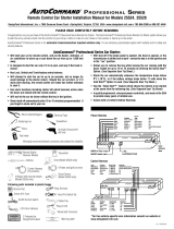
Wiring The Receiver To Any AVS ARC-7, ARC-T7 Or ARC-T9 Air Ride Controller
UP DOWN
Connecting the AVSREC4 receiver to any of our AVS ARC-T7, ARC-T9 or ARC-7 switch boxes requires three relays, one which
is for safety purposes. If for some reason the receiver was to malfunction while the vehicle is in motion, an accident could
result from it and cause property damage, personal injury or even death! INSTALL THE SAFETY RELAY!!! Adding the safety
relay will disconnect power to the switch box while the ignition key is on.
30
86
85
87
87A
(+) 12 VOLTS
TO BATTERY
GROUND
TAP INTO AN “ACCESSORY” OR “IGNITION” CIRCUIT.
THESE ARE CIRCUITS THAT HAVE +12V ONLY WHEN THE
IGNITION KEY IS TURNED ON. WHEN THE KEY IS OFF OR
OUT OF THE IGNITION THESE WIRES SHOULD NOT HAVE
Compatible With All ARC-T7, ARC-T9 And ARC-7 Air Ride Controllers
30
86
85
87
87A
30
86
85
87
87A
CONNECT TO THE LIGHT BLUE WIRE OF THE SWITCH
CONNECT TO THE GREY WIRE OF THE SWITCH BOX
CONNECT TO THE PINK WIRE OF THE SWITCH BOX
/