Page is loading ...

D20249 Rev 2 9/8/00
PRESSURE WASHER
OWNERS MANUAL
for
Model 3540CWHP
This product is not equipped with a spark arresting muffler. If the product will be used around
flammable materials, or on land covered with materials such as agricultural crops, forest, brush, grass, or
other similar items, then an approved spark arrester must be installed and is legally required in the state of
California. It is a violation of California statutes section 130050 and/or sections 4442 and 4443 of the Califor-
nia Public Resources Code, unless the engine is equipped with a spark arrestor, as defined in section 4442,
and maintained in effective working order. Spark arresters are also required on some U. S. Forest service
land and may also be legally required under other statutes and ordinances.
This product may contain chemicals known to the state of California to cause cancer, birth defects, or other
reproductive harm. This warning is given in compliance with California Proposition 65, as detectable amounts
of chemicals subject to proposition 65 may be contained in this product.
Read Owner's Manual. Do not operate equipment until you
have read Owners Manual for Safety, Assembly, Operation,
Maintenance and Storage Instructions.
ENGINE OIL MUST BE ADDED TO THE ENGINE BEFORE USE.
CAUTION

2 — ENG
D20249
Table of Contents ................................................... 2
Owner's Responsibilities ......................................... 2
Pressure Washer Return Policy ............................. 2
Warranty .................................................................. 3
Safety Rules ............................................................ 4
Unpacking ...............................................................6
Contents of Carton ................................................. 6
TABLE OF CONTENTS
Assembly ................................................................ 7
Operation .............................................................. . 9
Maintenance ......................................................... 15
Storage ................................................................. 16
Troubleshooting .................................................... 17
Repair Parts .......................................................... 18
Quick Facts .............................................. back page
Congratulations! You have purchased a high quality
product from America’s leading manufacturer of
pressure washers. This pressure washer, when
properly used and maintained, will provide trouble
free service. Please read and follow these instruc-
tions for proper use and maintenance.
• Read and understand all safety warnings.
• Read this Owner’s Manual. Save these instruc-
tions. Owner's manual should remain with unit
at all times.
• Do not operate this unit until you have read this
Owners Manual for Safety, Operation, and
Maintenance Instructions.
• Read the Engine Owner's Manual supplied
with this unit.
OWNER'S RESPONSIBILITIES
• Do not operate this unit until you have read the
Engine Owners Manual for Safety, Operation, and
Maintenance Instructions.
• Check for visible shipping damage. Shipping
damage will cause problems in operation of this
unit.
• If you experience any problems and need assis-
tance, please call us at our toll free number
1-800-888-2468, Ext 2. 8:00 a.m. to 8:00 p.m.
E.S.T.
• If you need warranty repair or service part pur-
chase, you can locate an Authorized Warranty
Service Center nearest you by calling us at
1-800-888-2468, Ext 2, 24 hours a day, 7 days a
week.
➜ Within 15 days of your purchase, Sam's will gladly exchange your pressure washer or refund your money.
Sales receipt is required.
➜ After 15 days manufacturer's warranty applies.
➜ Refer to this Owners Manual for manufacturer's warranty.
➜ If you need warranty repair or service part purchase, you can locate an Authorized Warranty Service Center
nearest you by calling us at 1-800-888-2468, Ext 2, 24 hours a day, 7 days a week.
PRESSURE WASHER RETURN POLICY
NOTE: Photos and illustrations in this manual are for reference only and may not represent a specific
model.
CAUTION indicates a potentially hazardous situation which, if
not avoided, may result in minor or moderate injury.
CAUTION used without the safety alert symbol indicates a
potentially hazardous situation which, if not avoided, may
result in property damage.
SAFETY GUIDELINES - DEFINITIONS
This manual contains information that is important for you to know and understand. This information relates to protecting
YOUR SAFETY and PREVENTING EQUIPMENT PROBLEMS. To help you recognize this information, we use the symbols
below. Please read the manual and pay attention to these sections.
DANGER indicates an imminently hazardous situation
which, if not avoided, will result in death or serious injury.
WARNING indicates a potentially hazardous situation
which, if not avoided, could result in death or serious
injury.
10/2/97

3 — ENG
D20249
WARRANTY
All merchandise manufactured by DeVilbiss Air Power Company Manufacturing is warranted to be free of defects in
workmanship and material which occur during the first year from the date of purchase by the original purchaser (initial user).
Products covered under this warranty include: air compressors, *air tools, accessories, service parts, pressure washers, and
generators used in consumer applications (i.e., personal residential household usage only).
Air compressors, *air tools, accessories, service parts, pressure washers, and generators used in commercial applications
(income producing) are covered by a 90 day warranty.
DeVilbiss Air Power Manufacturing will repair or replace, at DeVilbiss’ option, products or components which have failed
within the warranty period. Repair or replacement, and service calls on 60 and 80 gallon air compressors, will be handled
by Authorized Warranty Service Centers and will be scheduled and serviced according to the normal work flow and business
hours at the service center location, and depending on the availability of replacement parts.
All decisions of DeVilbiss Air Power Company Manufacturing with regard to this policy shall be final.
This warranty gives you specific legal rights, and you may also have other rights which vary from state to state.
Form: SP-100-H - 9/18/00
THIS WARRANTY DOES NOT COVER:
RESPONSIBILITY OF ORIGINAL PURCHASER (Initial User):
213 Industrial Drive • Jackson, TN 38301-9615
Telephone: 1-800-888-2468 , Ext. 2
FAX: 1-800-888-9036
❏ To process a warranty claim on this product, DO NOT return it to the retailer. The product must be evaluated by an
Authorized Warranty Service Center. For the location of the nearest Authorized Warranty Service Center call
1-800-888-2468, Ext. 2, 24 hours a day, 7 days a week or visit our web site @ devap.com.
❏ Retain original cash register sales receipt as proof of purchase for warranty work.
❏ Use reasonable care in the operation and maintenance of the product as described in the Owners Manual(s).
❏ Deliver or ship the product to the nearest DeVilbiss Air Power Manufacturing Authorized Warranty Service Center.
Freight costs, if any, must be paid by the purchaser.
❏ Air compressors with 60 and 80 gallon tanks only will be inspected at the site of installation. Contact the nearest
Authorized Warranty Service Center, that provides on-site service calls, for service call arrangement.
❏ If the purchaser does not receive satisfactory results from the Authorized Warranty Service Center, the purchaser
should contact DeVilbiss Air Power Company Manufacturing.
❏ Merchandise sold as reconditioned, floor models and/or display models. Any damaged or incomplete equipment sold
"as is".
❏ Merchandise used as "rental" equipment.
❏ Merchandise that has become inoperative because of ordinary wear, misuse, freeze damage, use of improper
chemicals, negligence, accident, improper and/or unauthorized repair or alterations including failure to operate the
product in accordance with the instructions provided in the Owners Manual (s) supplied with the product.
*Air Tools: O-Rings and driver blades are considered ordinary wear parts, therefore, they are warranted for a period
of 45 days from the date of purchase.
❏ An air compressor that pumps air more than 50% during a one hour period is considered misuse because the air
compressor is undersized for the required air demand. Maximum compressor pumping time per hour is 30 minutes.
❏ Merchandise sold by DeVilbiss Air Power Manufacturing which has been manufactured by and identified as the
product of another company. The product manufacturer's warranty will apply.
❏ Repair and transportation costs of merchandise determined not to be defective.
❏ Cost associated with assembly, required oil, adjustments or other installation and start-up cost.
❏ ANY INCIDENTAL, INDIRECT OR CONSEQUENTIAL LOSS, DAMAGE, OR EXPENSE THAT MAY RESULT
FROM ANY DEFECT, FAILURE OR MALFUNCTION OF THE PRODUCT. Some states do not allow the exclusion
or limitation of incidental or consequential damages, so the above limitation or exclusion may not apply to you.
❏ IMPLIED WARRANTIES, INCLUDING THOSE OF MERCHANTABILITY AND FITNESS FOR A PARTICULAR
PURPOSE, ARE LIMITED TO ONE YEAR FROM THE DATE OF ORIGINAL PURCHASE. Some states do not allow
limitations on how long an implied warranty lasts, so the above limitations may not apply to you.

4 — ENG
D20249
IMPORTANT SAFETY INSTRUCTIONS
IMPROPER OPERATION OR MAINTENANCE OF THIS PRODUCT COULD RESULT IN SERIOUS INJURY AND PROPERTY
DAMAGE. READ AND UNDERSTAND ALL WARNINGS AND OPERATING INSTRUCTIONS BEFORE USING.
HAZARD
• Unsafe operation of your pressure washer
could lead to serious injury or death to you
or others.
• If proper starting procedure is not
followed, engine can kickback causing
serious hand and arm injury.
• The spray gun/wand is a powerful cleaning
tool that could look like a toy to a child.
• Reactive force of spray will cause gun/wand
to move, and could cause the operator to
slip or fall, or misdirect the spray. Improper
control of gun/wand can result in injuries to
self and others.
• Become familiar with the operation and
controls of the pressure washer.
• Keep operating area clear of all persons,
pets, and obstacles.
• Do not operate the product when fatigued
or under the influenceof alcohol or drugs.
Stay alert at all times.
• Never defeat the safety features of this
product.
• Do not operate machine with missing,
broken, or unauthorized parts.
• Never leave wand unattended while unit is
running.
• If engine does not start after two pulls,
squeeze trigger of gun to relieve pump
pressure. Pull starter cord slowly until
resistance is felt. Then pull cord rapidly
to avoid kickback and prevent hand or
arm injury.
• Keep children away from the pressure
washer at all times.
• Do not overreach or stand on an unstable
support. Grip gun/wand firmly with both
hands. Expect the gun to kick when
triggered.
HOW TO PREVENT ITWHAT CAN HAPPEN
DANGER
DANGER
RISK TO BREATHING
RISK OF EXPLOSION
OR FIRE
RISK OF UNSAFE
OPERATION
WARNING
• Shut off engine and allow it to cool before
adding fuel to the tank.
• Use care in filling tank to avoid spilling fuel.
Move pressure washer away from fueling
area before starting engine.
• Keep maximum fuel level ½” below top of
tank to allow for expansion.
• Operate and fuel equipment in well
ventilated areas free from obstructions.
Equip areas with fire extinguishers suitable
for gasoline fires.
• Never operate pressure washer in an area
containing dry brush or weeds.
• Always keep pressure washer a minimum of
four feet away from surfaces (such as
houses, automobiles, or live plants) that
could be damaged from muffler exhaust
heat.
• Store fuel in an OSHA approved container,
in a secure location away from work area.
• Do not spray flammable liquids
• Spilled gasoline and it’s vapors can become
ignited from cigarette sparks, electrical arcing,
exhaust gases, and hot engine components
such as the muffler.
• Heat will expand fuel in the tank which could
result in spillage and possible fire explosion.
• Operating the pressure washer in an explosive
environment could result in a fire.
• Materials placed against or near the pressure
washer can interfere with its proper ventilation
features causing overheating and possible
ignition of the materials.
• Muffler exhaust heat can damage painted
surfaces, melt any material sensitive to heat
(such as siding, plastic, rubber, or vinyl), and
damage live plants.
• Improperly stored fuel could lead to acciden-
tal ignition. Fuel improperly secured could
get into the hands of children or other
unqualified persons.
• Use of acids, toxic or corrosive chemicals,
poisons, insecticides, or any kind of flam-
mable solvent with this product could result in
serious injury or death.
• Breathing exhaust fumes will cause serious
injury or death.
• Some cleaning fluids contain substances which
could cause injury to skin, eyes, or lungs.
• Operate pressure washer in a well venti-
lated area. Avoid enclosed areas such as
garages, basements ,etc.
• Never operate unit in a location occupied
by humans or animals.
• Use only cleaning fluids specifically
recommended for high pressure washers.
Follow manufacturers recommendations.Do
not use chlorine bleach or any other
corrosive compound

5 — ENG
D20249
WARNING
HAZARD
• Spray directed at electrical outlets or
switches, or objects connected to an
electrical circuit, could result in a fatal
electrical shock.
• Your washer operates at fluid pressures
and velocities high enough to penetrate
human and animal flesh, which could
result in amputation or other serious
injury. Leaks caused by loose fittings or
worn or damaged hoses can result in
injection injuries. DO NOT TREAT FLUID
INJECTION AS A SIMPLE CUT! See a
physician immediately!
• Relieve system pressure before attempt-
ing maintenance or disassembly of
equipment.
• Use of acids, toxic or corrosive chemi-
cals, poisons, insecticides, or any kind of
flammable solvent with this product
could result in serious injury or death.
• Contact with hot surfaces, such as
engines exhaust components, could
result in serious burn.
• Fuel or oil can leak or spill and could
result in fire or breathing hazard, serious
injury or death can result. Fuel or oil leaks
will damage carpet, paint or other
surfaces in vehicles or trailers.
• Unplug any electrically operated product
before attempting to clean it. Direct spray
away from electric outlets and switches.
• Never place hands in front of nozzle.
• Direct spray away from self and others.
• Make sure hose and fittings are tightened
and in good condition. Never hold onto
the hose or fittings during operation.
• Do not allow hose to contact muffler.
• Never attach or remove wand or hose
fittings while system is pressurized.
• Use only hose and high pressure
accessories rated for pressure higher than
your pressure washer's p.s.i.
• To relieve system pressure, shut off engine,
turn off water supply, and pull gun trigger
until water stops flowing.
• Do not use acids, gasoline, kerosene, or
any other flammable materials in this
product. Use only household detergents,
cleaners and degreasers recommended
for use in pressure washers.
• Wear protective clothing to protect
eyes and skin from contact with sprayed
materials.
• During operation, touch only the control
surfaces of the pressure washer. Keep
children away from the pressure washer
at all times. They may not be able to
recognize the hazards of this product.
• If pressure washer is equipped with a fuel
shut-off valve, turn the valve to the off
position before transporting to avoid fuel
leaks. If pressure washer is not equipped
with a fuel shut-off valve, drain the fuel from
tank before transporting. Only transport fuel
in an OSHA approved container. Always
place pressure washer on a protective mat
when transporting to protect against damage
to vehicle from leaks. Remove pressure
washer from vehicle immediately upon arrival
at your destination.
WHAT CAN HAPPEN HOW TO PREVENT IT
RISK OF
ELECTRICAL
SHOCK
RISK OF CHEMICAL BURN
RISK OF HOT SURFACES
RISK TO FLUID
INJECTION
WARNING
WARNING
WARNING
The powerful spray from your pressure washer is capable of causing damage to surfaces such as wood, glass,
automobile paint, auto striping and trim, and delicate objects such as flowers and shrubs. Before spraying, check the
item to be cleaned to assure yourself that it is strong enough to resist damage from the force of the spray. Avoid the
use of the concentrated spray stream except for very strong surfaces like concrete and steel.
Operating unit with water supply shutoff without flow of water will result in equipment damage. Operating the pressure
washer with water supply shutoff will void your warranty. You should never run this pressure washer for more than 2
minutes without pulling the trigger to allow cool water to enter the pump and the heated (recirculated) water to exit.
RISK OF INJURY AND
PROPERTY DAMAGE
WHEN
TRANSPORTING OR
STORING
DANGER
IMPORTANT SAFETY INSTRUCTIONS

6 — ENG
D20249
Handle
Engine Frame and
Wheel Assembly
Spray Gun
Quick Connect Wand
Nozzle Cleaning Kit
Quick Connect Nozzles
English
Owner's
Manual
Engine
Manual
Bagged Handle
High Pressure Hose
Bagged Parts
30 Weight
EngineOil
CONTENTS OF CARTON
Chemical Hose
(attached to barb
fitting on pump)
Spanish
Owner's
Manual
Instructional
Video
Handle Knobs
UNPACKING
1. Open carton.
2. Remove plastic bag containing handle, nozzles,
and engine manual supplied by engine manufac-
turer.
3. Remove cardboard from top of unit and inner
cardboard from around unit.
4. Remove plastic bag containing two knobs, nozzle
cleaning kit, instructional video, English Owner's
Manual, and Spanish Owner's Manual from carton.
5. Remove spray gun, quick connect wand, and
bottle of engine oil from carton.
6. Using box cutting tool, cut the four corners of the
shipping carton from top to bottom, then lay
panels flat. NOTE: Be careful not to cut into
chemical hose and high pressure hose.
7. Insert handle ends into pressure washer frame as
shown.
8. Install two knobs as shown and tighten securely.
9. Grasp handle and roll unit off of carton.
10. Remove high pressure hose from carton and store
in gun/hose holder as shown in Pressure Washer
Basics section in this manual.
Knobs

7 — ENG
D20249
1. Connect threaded end of quick connect wand to
spray gun as shown. Tighten securely.
ASSEMBLY
ASSEMBLY
2. Place assembled spray gun, quick connect, wand,
and chemical hose in gun/hose holder.
3. Add 30 weight engine oil (supplied) to engine.
Refer to engine manual supplied by engine manu-
facturer for procedure. Do not overfill. Use of a
funnel is recommended.
NOTE
There will be a slight amount of oil in the
engine from factory testing.
NOTE
The engine on this pressure washer is
equipped with a low oil sensor. The amount
of oil in the engine must be correct or the
engine will not start.
THE PUMP IS SHIPPED FROM THE FAC-
TORY WITH OIL IN IT AND A RED SHIP-
PING PLUG TO PREVENT ANY OIL FROM
LEAKING OUT OF THE PUMP DURING
SHIPMENT. ATTACHED TO THE SHIPPING
PLUG IS A PLASTIC BAG (SEE THE FOL-
LOWING PHOTO) WHICH CONTAINS THE
DIPSTICK/OIL PLUG THE SHIPPING PLUG
MUST BE REMOVED AND THE DIPSTICK/
OIL PLUG INSTALLED BEFORE THE PRES-
SURE WASHER IS OPERATED.
4. Using a 17 mm wrench, remove shipping plug
from pump by turning it counterclockwise. Dis-
card plug.
5. Remove dipstick/oil plug from plastic bag. Before
installing dipstick/oil plug into pump, check the
pump oil level. See Pump paragraph in Mainte-
nance section of this manual.
6. Remove five colored quick connect nozzles from
plastic bag and insert them into correct receptacle
on panel NOTE: Nozzles are color coded to
match colored squares on panel.

8 — ENG
D20249
NOTE: Become familiar with the controls and features described on these pages before
operating your unit.
OPERATION
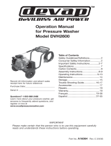
BASIC ELEMENTS OF A PRESSURE
WASHER
High Pressure Pump: Increases the pressure of the
water supply to 3500 psi @ 4 gpm.
13HP Honda Engine: Drives the high pressure pump.
High Pressure Hose: Carries the pressurized water
from the pump to the gun and wand.
Spray Gun: Connects with wand to control water flow
rate, direction, and pressure.
Quick Connect Wand: Used to aim the pressurized
water spray.
Quick Connect Nozzles: Develops the spray pattern
and restricts the water flow so water pressure can be
maintained.
Chemical Hose: Allows cleaners or cleaning solvents
to be mixed with the pressurized water stream. See
How To Siphon Chemicals/Cleaning Solvents in
Operation section of this manual.
Pressure Regulator/Unloader: Adjust output pres-
sure of pump.
Thermal Relief Valve: A safety device that protects
the pump from overheating. When water inside the
pump reaches a specified temperature, the thermal
relief valve opens and discharges the heated water
from the pump.
EZ Start Valve: Allows the starter cord on the engine
to be pulled without causing a pressure build up in the
hose.
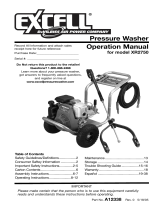
BASIC ELEMENTS OF ENGINE
Fuel Valve Lever: Opens and closes connection
between fuel tank and carburetor.
Engine Switch: Enables and disables ignition system.
Choke Control Lever: Opens and closes the choke
valve in carburetor.
Throttle Control Lever: Controls engine speed.
Starter Grip: Pulling starter grip operates recoil
starter to crank engine.
Spray
Gun
3/8" X 50 ft. High-
Pressure Hose
Quick
Connect
Wand
High Pressure
Pump
Heavy Duty
Steel Frame
Detachable
Handle for
Storage
13 HP Honda Engine
Chemical
Injection
Hose
With Filter
Quick
Connect
Nozzles
Pressure
Regulator
Thermal
Relief
Valve
13”
Pneumatic
Knobby Tires
Gun/Hose
Holder
By-Pass
Hose
Chemical
Injector
EZ Start
Valve
Starter
Grip
Recoil
Starter
Throttle
Control Lever
Spark
Plug
Choke
Control
Air
Cleaner
Muffler
Fuel
Valve
Lever

9 — ENG
D20249
OPERATION
OPERATING FEATURES OF YOUR
PRESSURE WASHER
BYPASS MODE
During normal operation water supply is turned on,
engine is running, spray gun trigger is depressed, and
the cold water supply circulates inside the pressure
washer pump allowing pump to maintain a safe
operating temperature. When you release spray gun
trigger and engine is still running, you are in bypass
mode.
When unit is in bypass mode, water circulating inside
the pump begins to heat up. If unit is left in bypass
mode for more than two (2) minutes, the water tem-
perature will rise to a dangerous level and damage
internal components of the pump.
If pressure washer is operated without an adequate
water supply or operated for more than two (2) min-
utes without depressing the spray gun trigger, the
pump will overheat and be seriously damaged. Any
damage to pump due to these causes will not be
covered under warranty.
THERMAL RELIEF VALVE
In an effort to prevent damage, pumps are equipped
with a thermal relief valve. This valve will open when
the temperature inside the pump rises too high. This
valve will then release a gush of water in an effort to
lower the temperature inside the pump. Immediately
after this occurs, the valve will close.
DO NOT allow your unit to operate in
bypass mode for more than two minutes at
any time. Overheating of pump will cause
damage to pump.
PRESSURE ADJUSTMENT
DO NOT attempt to increase pump
pressure. A higher pressure setting than
the factory set pressure will damage pump.
The pressure output of the pump is preset at the
factory to achieve optimum pressure and cleaning. If
you need to lower the pressure, it can be accomplished
by one of these three methods:
1. Back away from the surface being cleaned. The
farther away you are, the less pressure is delivered
to the surface being cleaned.
2. Adjust the pressure regulator knob on the pump.
a. Turn the pressure regulator knob counter-
clockwise.
b. Once you have finished using your pressure
washer, return the pressure regulator knob to
its original position by turning it clockwise until
it stops.
DO NOT try to turn pressure regulator knob
past the built-in stop or damage to pump
will result
3. Reduce the speed of the gasoline engine (RPM).
Slow engine down and water pressure will go
down with it.
SPRAY NOZZLES
Your pressure washer is equipped with five spray
nozzles. Each nozzle is color coded and delivers a
specific spray pattern for a particular cleaning pur-
pose. The size of the nozzle determines the size of the
fan spray and the pressure out of the nozzle. The 0
O
,
15
O
, 25
O
, and 40
O
nozzles are high pressure nozzles.
The chemical nozzle is a low pressure nozzle.
Pressure
Regulator
Knob
PRESSURE WASHER TERMINOLOGY
PSI: Pounds per Square Inch. The unit of measure
for water pressure. Also used for air pressure, hy-
draulic pressure, etc.
GPM: Gallons Per Minute. The unit of measure for
the flow rate of water through the pressure washer.
CU: Cleaning Units. GPM multiplied by PSI.
Bypass Mode: In Bypass Mode, the pump is recircu-
lating water because the trigger of the spray gun is
not pulled.
Chemical Injection: Feeds cleaning agents into the
pump to mix with the pressurized water and help in
cleaning.
Water Supply: All pressure washers must have a
source of water. The minimum requirements for a
water supply are 20 PSI and 5 gallons per minute.
NOTE: Any supply pressure or delivery rate less than
this will not allow the pressure washer to operate at its
full potential.

10 — ENG
D20249
PRESSURE WASHER BASICS
Larger Hole
HOW TO SIPHON CHEMICALS/CLEANING
SOLVENTS
Siphoning chemicals or cleaning solvents is a low
pressure operation.
NOTE
Use only soaps and chemicals designed for
pressure washer use. Do not use bleach.
To siphon chemicals:
1. Press chemical hose onto barbed fitting located
near high pressure hose connection of pump as
shown.
Barbed
Fitting
2. Place other end of chemical hose with filter on it
into container holding chemical/cleaning solution.
3. Install low pressure (black) nozzle into quick
connect fitting of wand as shown.
OPERATION
Quick Connect
Coupler
4. After use of chemical, siphon clean water through
chemical hose to rinse it and pump clean. Chemi-
cals which remain in pump can damage it. Damage
to pump due to chemicals will not be covered
under warranty.
NOTE
Chemicals and soap will not siphon when
using high pressure nozzles.
The nozzles are housed in receptacles on the panel of
the pressure washer handle. Color squares on the
panel identify nozzle location and spray pattern.
NOTE
A nozzle is easier to remove from its
receptacle if it is pushed from underneath
while it is being pulled from above.
RISK OF INJECTION OR INJURY TO
PERSON. DO NOT DIRECT DISCHARGE
STREAM TOWARD PERSONS.
WHEN USING THE HIGH PRESSURE
NOZZLES, DO NOT ALLOW THE JET-LIKE
SPRAY TO COME IN CONTACT WITH
UNPROTECTED SKIN, EYES, OR WITH
ANY PETS OR ANIMALS. SERIOUS IN-
JURY CAN OCCUR.
0
O
nozzle - Red. This nozzle delivers a pinpoint
stream and is extremely powerful. It covers a very
small area of cleaning. This nozzle should only be
used on surfaces that can withstand this high pres-
sure such as metal or concrete. Do not use on wood.
15
O
nozzle - Yellow. This nozzle delivers a powerful
15 degree spray pattern for intense cleaning of small
areas. This nozzle should only be used on areas that
can withstand the high pressure from this nozzle.
25
O
nozzle - Green. This nozzle delivers a 25 degree
spray pattern for intense cleaning of larger areas.
This nozzle should only be used on areas that can
withstand the pressure from this nozzle.
40
O
nozzle - White. This nozzle delivers a 40 degree
spray pattern and a less powerful stream of water. It
covers a wide area of cleaning. This nozzle should be
used for most general cleaning jobs.
Chemical nozzle - Black. This nozzle is used to
apply chemicals or cleaning solutions. It has the least
powerful stream.
CHANGING NOZZLES
DO NOT attempt to change nozzles while
pressure washer is running. Turn engine
off before changing nozzles.
To change nozzles on the wand:
1. Pull quick connect coupler back and insert nozzle.
2. Release quick connect coupler and twist nozzle to
make sure it is secure in coupler.

11 — ENG
D20249
OPERATION
BEFORE STARTING
1. Move pressure washer to level ground.
2. Check engine oil level. Refer to engine
manufacturer's manual for procedure.
NOTE
The engine on this pressure washer is
equipped with a low oil sensor. The amount of
oil in the engine must be correct or the engine
will not start.
3. Make sure shipping plug on pump has been
replaced with dipstick/oil plug. See Assembly
section in this manual.
4. Check oil level in pump. See Pump paragraph in
the Maintenance section for correct procedure.
5. Select a nozzle for your cleaning job. See
Nozzles in this section.
6. Install desired nozzle into quick connect coupler.
See Changing Nozzles in this section.
7. Make sure screen filter is in water inlet of pump,
as shown.
10. Attach other end of high pressure hose to quick
connect fitting on pump as shown.
Screen Filter
Never pull water supply hose to move unit. This
could damage hose and/or pump inlet.
9. Attach one end of high pressure hose to spray gun
as shown. This is a quick connect fitting and
requires no tightening.
8. Connect male end of water supply hose to water
inlet of pump as shown.
NOTE
The water supply must provide a minimum
of 5 gallons per minute at 20 PSI.
NOTE
Use cold water only.
Water
Supply
Hose
High
Pressure
Hose
11. Make sure high pressure hose and water supply
hose are securely connected to pump.
12. If you are applying a chemical or cleaning solution,
See How To Siphon Chemicals/Cleaning
Solvents in Operation section of this manual.
13. Turn water supply on.

12 — ENG
D20249
14. Add fresh, unleaded regular gasoline to engine
fuel tank.
TYPICAL HOOK-UP
Your pressure washer hookup should resemble this
diagram.
OPERATION
NEVER FILL FUEL TANK INDOORS. NEVER
FILL FUEL TANK WHEN ENGINE IS RUN-
NING OR HOT. DO NOT SMOKE WHEN FILL-
ING FUEL TANK.
NEVER FILL FUEL TANK COMPLETELY. FILL
TANK TO 1/2" BELOW BOTTOM OF FILLER
NECK TO PROVIDE SPACE FOR FUEL EX-
PANSION. WIPE ANY FUEL SPILLAGE FROM
ENGINE AND EQUIPMENT BEFORE START-
ING ENGINE.
NEVER RUN ENGINE INDOORS OR IN EN-
CLOSED, POORLY VENTILATED AREAS.
ENGINE EXHAUST CONTAINS CARBON
MONOXIDE, AN ODORLESS AND DEADLY
GAS.
PRE-START CHECKLIST
Once you reach this point, ensure you have completed
the following:
All safety instructions read and understood?
All hose connections are tightened and free of
any kinks, damage, or leaks?
Correct amount of engine oil and gasoline
added to engine?
Correct amount of oil in the pump?
Nozzle installed in end of wand?
Water supply (garden hose) turned on?
All operation instructions read and under-
stood?
If you can say "yes" to the items on the Pre-start
checklist, you are ready to start your pressure washer.
Garden
Hose
Chemical
Chemical
Hose
Hi-
Pressure
Hose
Pressure Washer
Wand
STARTING YOUR PRESSURE
WASHER
NOTE: Make sure water supply is turned on.
Never turn water supply off while pressure
washer engine is running or damage to
pump will result.
1. Move fuel valve lever to ON position.
2. Move choke control lever to CLOSED position.
NOTE
To restart a warm engine, move choke control
to ON position.
Fuel
Valve
Lever
ON
Choke Control
Lever
CLOSED
ON

13 — ENG
D20249
OPERATION
3. Move throttle control lever out of SLOW position,
about 1/3 of the way toward FAST position.
Throttle Control
Slow
Engine Switch
OFF
ON
5. Pull starter grip slowly until you feel resistance,
then pull briskly. Return starter grip gently.
Starter Grip
If engine does not start after two pulls, pull
the trigger on spray gun to relieve pressure
in hose. Failure to do so may cause dam-
age to starter recoil mechanism of engine
NEVER RUN ENGINE INDOORS OR IN EN-
CLOSED, POORLY VENTILATED AREAS.
ENGINE EXHAUST CONTAINS CARBON
MONOXIDE, AN ODORLESS AND DEADLY
GAS.
4. Turn engine switch to ON position.
6. If choke control lever is in CLOSED position, move
lever to OPEN position as engine warms up.
7. Move throttle control to FAST position.
WHEN USING THE HIGH PRESSURE
SETTING, DO NOT ALLOW THE HIGH
PRESSURE SPRAY TO COME IN CONTACT
WITH UNPROTECTED SKIN, EYES, OR
WITH ANY PETS OR ANIMALS. SERIOUS
INJURY CAN OCCUR.
DO NOT stop spraying water for more than
two minutes at a time. Pump operates in
bypass mode when spray gun trigger is not
pressed. If pump is left in bypass mode for
more than two minutes internal components
of the pump can be damaged.
DO NOT let hoses come in contact with
very hot engine muffler during or immedi-
ately after use of your pressure washer.
Damage to hoses from contact with hot
engine surfaces will NOT be covered by
warranty.
7. Depress trigger on gun to start water flow. Release
trigger to stop water flow.
STAND ON A STABLE SURFACE AND GRIP
GUN/WAND FIRMLY WITH BOTH HANDS.
EXPECT THE GUN TO KICK WHEN
TRIGGERED.
9. Adjust nozzle spray for the task being performed.
See Spray Nozzle instructions in the Operation
section.
Throttle Control
Fast
Fast
Slow

14 — ENG
D20249
SHUTTING DOWN YOUR PRESSURE
WASHER
1. If you have siphoned chemicals or cleaners, you
must siphon clean water through chemical hose to
flush chemical injector.
2. Continue to siphon clean water through hose and
pump for at least one minute before turning off
engine.
NOTE
Failure to siphon clean water through chemical
hose and pump after siphoning chemicals or
cleaners can cause damage to pump.
3. Move throttle control to STOP position to stop
engine.
4. Turn engine switch to OFF position.
OPERATION
Throttle Control
Fast
Slow
Engine Switch
OFF
ON
5. Move fuel valve lever to OFF position.
Fuel
Valve
Lever
ON
OFF
6. Turn off water supply.
Never turn water supply off while pressure
washer engine is running or damage to
pump will result.
DO NOT let hoses come in contact with
very hot engine muffler during or immedi-
ately after use of your pressure washer.
Damage to hoses from contact with hot
engine surfaces will NOT be covered by
warranty.
7. Pull trigger on spray gun to relieve any water
pressure in hose or spray gun.
8. Disconnect water supply hose from pump.
9. Coil high pressure hose and store in gun/hose
holder.
10. Place spray gun in gun/hose holder.
11. Place chemical hose in gun/hose holder.

15 — ENG
D20249
WHEN DOING MAINTENANCE, YOU MAY BE EXPOSED TO HOT SURFACES, WATER PRESSURE,
MOVING PARTS, OR FIRE RESULTING IN DEATH. BEFORE PERFORMING ANY MAINTENANCE OR
REPAIR, DISCONNECT SPARK PLUG WIRE, LET ENGINE COOL AND RELEASE ALL WATER PRES-
SURE. THE ENGINE CONTAINS FLAMMABLE FUEL. DO NOT SMOKE OR WORK NEAR OPEN
FLAMES WHILE PERFORMING MAINTENANCE.
ENGINE
1. Consult Engine Owner's Manual for manufacturer's
recommendations for any and all engine mainte-
nance.
PUMP
The Annovi Reverberi (AR) pump on your pressure
washer was shipped from the factory with oil. The oil
in your pump must be changed after the first 10 hours
of use and every 50 hours thereafter.
To Check Oil:
To ensure efficient operation and longer life of your pressure washer, a routine maintenance schedule should be
prepared and followed. The following routine maintenance schedule is geared to an unit in a normal working
environment. If necessary, the schedule should be modified to suit the conditions under which your pressure washer
is used. The modifications will depend upon the hours of operation and the working environment. If the pressure
washer is in an extremely dirty and/or hostile environment it will require a greater frequency of all maintenance
checks.
MAINTENANCE
b. If your AR pump does not have a side drain
plug, drain the pump by removing the bottom
drain plug on the underside of the pump with
an 8 mm Allen wrench.
2. Drain oil into a suitable container.
3. Replace oil drain plug and tighten securely.
4. Remove oil fill plug (or dipstick).
5. Add 18.5 oz of 30W non-detergent oil to pump.
6. Replace oil fill plug and tighten securely.
HOW TO CLEAN THE NOZZLES
If a spray nozzle becomes clogged with foreign
material such as dirt, excessive pump pressure may
develop and the spray pattern will change. If a nozzle
becomes partially clogged or restricted, the pump
pressure will pulsate. If this happens, clean the nozzle
immediately using the nozzle cleaning kit supplied with
your pressure washer. The procedure is as follows:
1. Shut off pressure washer and turn off water
supply.
2. Pull trigger on spray gun to relieve any water
pressure.
3. Disconnect quick connect wand from spray gun.
4. Remove nozzle from wand.
5. Inspect nozzle for obstructions, grime, or any
foreign matter that could restrict flow of water.
6. Remove any obstructions with nozzle cleaning
tools provided and back flush with clean water.
7. Direct water supply into nozzle end for 30 seconds
to back flush loosened particles.
8. Take this opportunity to inspect wand for obstruc-
tions. Back flush wand if obstructions are seen.
9. Reassemble nozzle to wand.
10. Reconnect wand to spray gun and turn on water
supply.
11. Start pressure washer and test spray pattern. See
Nozzles in Operation section.
12. If spray pattern is still incorrect, replace nozzle.
1. For units with sight glass:
a. If oil level is low, add oil so oil level is midway
between high and low marks on sight glass.
b. If oil level is high, remove excess oil so oil level
is midway between high and low marks on
sight glass.
2. For units with dipstick:
a. Remove dipstick from pump and wipe clean.
b. Insert dipstick fully into pump, then remove it.
c. Oil level is correct when oil covers the lower 1/2
inch of end of dipstick.
To Change Oil:
1. Remove drain plug using one of the methods
below:
a. If your AR pump has a side drain plug, use a
17 mm wrench to remove the plug and drain
the pump.
Sight
Glass
Side
Drain
Plug
Oil Fill
Plug
Bottom Drain Plug
(underneath pump)

16 — ENG
D20249
MAINTENANCE
PREPARATION FOR STORAGE
It is recommended that you follow these steps to
protect the internal seals of the pressure washer when
storing the unit for an extended period and WHEN
FREEZING TEMPERATURES ARE EXPECTED.
ENGINE
1. Remove gasoline from engine or add fuel stabi-
lizer, such as "Sta-Bil" to gasoline to prevent
gumming
2. If you are adding fuel stabilizer, connect water
supply and high pressure hose to pump and spray
gun.
3. Turn water supply on and start engine.
4. Squeeze spray gun trigger while engine is running
to avoid operating pump in ""bypass mode"".
5. Run engine for five minutes, then shut engine off.
6. Disconnect water supply.
7. Disconnect spark plug wire and remove spark
plug.
8. Pour one teaspoon of engine oil into spark plug
hole.
9. Place a rag over the spark plug hole and pull
starter rope slowly several times to lubricate
internal cylinder wall.
PUMP
NOTE: If storing the unit for more than 30 days
RV antifreeze needs to be ran through the
pump. This helps prevent damage within the
pump head. RV antifreeze is not only added for
winterizing, but for proper lubrication regard-
less of temperature or environment. Storing the
pump less than 30 days does not require the
RV antifreeze.
1. Obtain a funnel, six ounces of RV antifreeze, and
approximately 12 inches of garden hose with a
male hose connector attached to one end.
Use only RV antifreeze. Any other anti-
freeze is corrosive and can damage pump.
2. Disconnect high pressure hose from pump and
from spray gun.
3. Connect 12 inch length of hose to water inlet of
pump.
4, Add RV antifreeze to hose as shown.
5. Pull engine starter rope slowly several times until
antifreeze comes out of high pressure hose
connection of pump.
6. Remove short hose from water inlet of pump.
7. Install spark plug into spark plug hole and tighten
securely, then reconnect spark plug wire.
8. Drain all water from high pressure hose, coil it, and
store it in cradle of pressure washer handle.
9. Drain all water from spray gun and wand by
holding spray gun in a vertical position with nozzle
end pointing down and squeezing trigger. Store in
cradle on pressure washer handle.
10. Store nozzles in color matching receptacles on flat
panel of pressure washer handle.
11. Store chemical hose, high pressure hose, spray
gun, and wand so they are protected from dam-
age, such as being run over.
STORAGE
HOW TO CLEAN THE WATER INLET FILTER
This screen filter should be checked periodically and
cleaned if necessary.
1. Remove filter by grasping end and removing it
from water inlet of pump as shown.
2. Clean filter by flushing it with water on both sides.
3. Install filter into water inlet of pump.

17 — ENG
D20249
Engine will not start
(see Engine Manual for
further engine trouble-
shooting)
No or low pressure
(initial use)
Will not draw chemicals
No or low pressure after
a period of normal use.
Water leaking at gun to
wand connection
Water leaking at pump
Oil leaking at pump
1. No fuel.
2. Low oil (if oil-alert equipped).
3. Pressure buildup after initial use.
4. Not primed or choked.
5. Spark plug wire not attached.
6. Engine ON/OFF switch in OFF
position (If equipped.)
1. Wrong nozzle selected.
2. Low water supply.
3. Leak at high pressure hose.
4. Nozzle obstructed.
5. Water filter screen clogged.
6. Defective E-Z start valve.
(If applicable)
7. Air trapped in hose.
1. Low pressure nozzle not in
wand.
2. Chemical filter clogged.
3. Chemical hose not in chemical.
1. Worn seal or packing.
2. Worn or obstructed valves.
1. Worn o-ring.
2. Loose hose connection.
1. Loose connections.
2. Piston packings worn.
1. Oil seals worn.
2. Loose drain plug.
3. Worn fill plug o-ring.
5. Pump overfilled.
5. Incorrect oil used.
1. Add fuel.
2. Add required amount of oil.
3. Squeeze gun trigger to relieve pres-
sure.
4. Push primer bulb 3 times or choke
engine.
5. Attach spark plug wire.
6. Place engine ON/OFF switch to ON
position.
1. Refer to page 11 for proper nozzle
selection.
2. Water supply must be at least 5 GPM
@ 20 PSI
3. Repair leak. Apply thread sealing tape
if necessary.
4. Clean nozzle with nozzle cleaning tool,
flush out obstruction with clean water.
5. Remove and clean filter.
6. Check with Authorized Warranty
Service Center (AWSC.)
7. Turn off engine, then water supply.
Disconnect water supply from pump
inlet, then turn water supply on to
remove all air from hose. When there is
a steady stream of water present, turn
water supply off. Reconnect water
supply to pump inlet and turn on water
supply. Squeeze trigger of spray gun
to remove remaining air.
1. See Using Chemicals/Cleaning Sol-
vents in the Operation section.
2. Clean filter. See How To Clean Water
Inlet Filter in Maintenance section.
3. Ensure end of chemical hose is fully
submerged into chemical.
1. Have replaced by AWSC.
2. Have replaced by AWSC.
1. Check and replace.
2. Tighten connection. If leak persists,
disassemble connection, apply thread
sealing tape to threads and reassemble
1. Tighten.
2. Have replaced by AWSC.
1. Have replaced by AWSC.
2. Tighten.
3. Check and replace.
4. Check for correct amount.
5. Drain and fill with correct amount
and type of oil.
PROBLEM
CAUSE
CORRECTION
TROUBLESHOOTING

18 — ENG
D20249
REPAIR PARTS
6
5
7
1
8
9
2
3
4
10
1 * Honda Engine Model Number PS-GX-340K1QA
2 ^ AR- Horizontal Pump
3 16756 High Pressure Hose
4 17698 Trigger Gun
5 17776 Wand with 22 mm adaptor
6 17730 Nozzle Kit
includes 0°,15°,25°,40°, and Chemical/Soap Nozzle
7 H100 Chemical Hose
8 17413 Tire
9 F464 Pal Nut
10 NCT001 Nozzle Cleaning Kit
11 17617 Handle Grip
12 17926 Foot (qty 2)
* Contact your local engine dealer for parts and service.
^ Contact an Authorized Warranty Service Center near you, call 1-800-888-2468, Ext. 2.
12
11
11

19 — ENG
D20249
NOTES

DeVilbiss Air Power Company • 213 Industrial Drive • Jackson, TN 38301-9615
QUICK FACTS
CALL 1-800-888-2468 EXT. 2
TO FIND A LOCAL AUTHORIZED SERVICE CENTER NEAR YOU
FOR REPAIRS AND SERVICE PART PURCHASES.
GAS
Use fresh high quality gas.
Add stabilizer to fuel tank and run engine for 5 minutes before storage.
OIL
Pump oil: Refer to owners manual supplied with this unit.
Engine oil: Refer to engine manual supplied with this unit.
Some units are equipped with a low oil sensor and adequate oil must be added or
the unit will not start.
WATER
Use only cold water.
Don’t operate unit with clogged or missing water filter/screen.
Don’t operate unit without adequate water supply to pump. Adequate water supply is
a minimum of 20 psi and 5 gpm.
PRESSURE
ADJUSTMENT
The pressure setting is preset at the factory to achieve optimum cleaning. If you
need to lower the pressure setting, refer to the owners manual for proper procedure.
PUMP
Pull gun trigger every 2 minutes while engine is running.
Don’t allow water to freeze in pump.
Siphon RV antifreeze into pump for cold weather storage or long term storage.
BY-PASS
MODE
Never leave unit running for more than 2 minutes without pulling gun trigger; doing so
will destroy pump and void warranty.
THE RMAL
RELIEF VALVE
Pump is equipped with a thermal relief valve. If the water overheats, this valve will
open and allow a gush of water to escape. Once the water is released, the valve
closes allowing the pump to operate normally.
HOSE
Don’t allow hoses to contact the HOT engine muffler during or after use.
Never pull the hose to move the unit.
ENGINE
Do not adjust or attempt maintenance without consulting engine manual or an
authorized engine service center.
Add stabilizer to fuel tank and run engine for 5 minutes before storage.
Always turn on the water before starting the engine.
SOAP
CHEMICALS
Use only soaps and chemicals designed for pressure washer use.
NOZZLE
Keep nozzle unclogged. Refer to manual for cleaning procedures.
Chemical/soap cannot be siphoned in high pressure setting. Only in low setting.
MAINTENANCE
SCHEDULE
Follow recommended maintenance schedule for engine & pump. Refer to manuals.
STORAGE
OR
WINTER
STORAGE
Draw clean water throu
g
h chemical inlet.
Add stabilizer to fuel tank and run engine for 5 minutes before storage.
Don’t allow water to freeze in pump, gun, wand or hoses.
Siphon RV antifreeze into pump for cold weather storage or long term storage.
ALWAYS REFER TO THE MANUALS SUPPLIED WITH THIS UNIT
Pressure Washer Quick Facts
/