Ubiquiti Networks TOUGH Switch PoE PRO TS-8-PRO User manual

Category
Networking
Type
User manual
Power over Ethernet Managed Switches
Models: TS-5-POE, TS-8-PRO, TS-16-CARRIER
i
Table of ContentsTOUGHSwitch
PoE User Guide
Ubiquiti Networks, Inc.
Table of Contents
Chapter 1: Overview ................................................1
Introduction. . . . . . . . . . . . . . . . . . . . . . . . . . . . . . . . . . . . . . . . . . . . . . . . . . . . . . . . . . . . . . . . . . . . . . 1
Package Contents ................................................................1
Configuration Interface System Requirements. . . . . . . . . . . . . . . . . . . . . . . . . . . . . . . . . . . . . 1
Hardware Overview ..............................................................1
Chapter 2: Installation ..............................................6
Introduction. . . . . . . . . . . . . . . . . . . . . . . . . . . . . . . . . . . . . . . . . . . . . . . . . . . . . . . . . . . . . . . . . . . . . . 6
Configuration ....................................................................6
Installation of the TOUGHSwitch PoE ..............................................6
Installation of the TOUGHSwitchPoEPRO .........................................8
Installation of the TOUGHSwitchPoECARRIER .....................................9
Chapter 3: Navigation .............................................11
Accessing the Configuration Interface ...........................................11
Configuring the TOUGHSwitch PoE CARRIER .....................................12
Product Verification .............................................................12
Interface Tabs ...................................................................12
Chapter 4: Status Tab ..............................................13
Status ...........................................................................14
Port Status ......................................................................14
Port Statistics ....................................................................14
Total Throughput ................................................................15
Data Distribution ................................................................15
Details for Port ..................................................................15
Chapter 5: Device Tab .............................................17
Firmware Update ................................................................18
Management Network Settings ..................................................18
Basic Settings ...................................................................19
Management Connection Settings ...............................................19
Services .........................................................................20
Spanning Tree Protocol ..........................................................21
Jumbo Frames. . . . . . . . . . . . . . . . . . . . . . . . . . . . . . . . . . . . . . . . . . . . . . . . . . . . . . . . . . . . . . . . . . .21
Device Discovery ................................................................22
System Accounts ................................................................22
Device Maintenance .............................................................22
Configuration Management .....................................................22
ii
Table of ContentsTOUGHSwitch
PoE User Guide
Ubiquiti Networks, Inc.
Chapter 6: Ports Tab ..............................................23
Basic Settings for Port ...........................................................24
Ping Watchdog for Port ..........................................................24
Spanning Tree Settings for Port ..................................................25
Configure Alerts for Port .........................................................25
Chapter 7: VLANs Tab .............................................26
VLANs ...........................................................................26
Trunk ...........................................................................27
Chapter 8: Alerts Tab ..............................................28
Alert Log ........................................................................28
System Log ......................................................................29
Chapter 9: Tools ...................................................30
MAC Forwarding Table ..........................................................30
Ping .............................................................................31
Traceroute ......................................................................31
Discovery .......................................................................31
Appendix A: Specifications ........................................32
Appendix B: Safety Notices ........................................34
Electrical Safety Information .....................................................34
Appendix C: Warranty .............................................35
Limited Warranty ................................................................35
Appendix D: Compliance Information .............................37
FCC .............................................................................37
Industry Canada .................................................................37
Australia and New Zealand ......................................................37
CE Marking ......................................................................37
RoHS/WEEE Compliance Statement ..............................................37
Appendix E: Declaration of Conformity ............................39
Appendix F: Contact Information ..................................40
Ubiquiti Networks Support ......................................................40
1
Chapter 1: OverviewTOUGHSwitch
PoE User Guide
Ubiquiti Networks, Inc.
TOUGHSwitch PoE PRO
8-Port Power over Ethernet
Managed Switch PRO
Model: TS-8-PRO
TOUGHSwitch PoE PRO Power Cord Quick Start Guide
TOUGHSwitch PoE CARRIER
TOUGHSwitch PoE CARRIER Power Cords (Qty. 2)
Rackmount
Power over Ethernet
Managed Switches
Model: TS-16-CARRIER
#10-32 x 5/8" Phillips
Screws (Qty. 4)
M3x8 Flathead
Screws (Qty. 2)
#10-32 x 5/8"
Cage Nuts (Qty. 4)
Quick Start Guide
Configuration Interface System
Requirements
Microsoft Windows XP, Windows Vista, Windows 7,
Windows 8, Linux, or Mac OS X
Java Runtime Environment 1.6 (or above)
Web Browser: Mozilla Firefox, Apple Safari, Google
Chrome, or Microsoft Internet Explorer 8 (or above)
Hardware Overview
Proceed to the description for your TOUGHSwitch model:
“TOUGHSwitch PoE” on page 2
“TOUGHSwitch PoE PRO” on page 3
“TOUGHSwitch PoE CARRIER” on page 4
Chapter 1: Overview
Introduction
Thank you for purchasing the Ubiquiti TOUGHSwitch
PoE,
which is part of the TOUGHSwitch series:
Name Model Description
TOUGHSwitch PoE TS-5-POE 5-port managed
switch featuring
24VPoE
TOUGHSwitch PoE PRO TS-8-PRO 8-port managed
switch featuring
24V/48V PoE
TOUGHSwitch PoE CARRIER TS-16-CARRIER Two TOUGHSwitch
PoE PROs mounted
in a rack
The TOUGHSwitch is a managed switch designed
to deliver Power over Ethernet (PoE) on the
10/100/1000ports you have configured for PoE. It also
features a variety of features, including port monitoring,
system connection and management services, Virtual
Local Area Network (VLAN) configuration, Spanning Tree
Protocol (STP), Ping Watchdog, and alerts setup.
This User Guide is designed to provide instructions about
installation of the TOUGHSwitch and to provide details
about how to set up and use the Configuration Interface.
This intuitive interface allows you to conveniently manage
your TOUGHSwitch using your web browser.
Package Contents
TOUGHSwitch PoE
TOUGHSwitch PoE M2.9x20 Screws
(Qty. 2)
M2.9 Anchors
(Qty. 2)
5-Port Power over Ethernet
Managed Switch
Model: TS-5-POE
Power Adapter
(24V, 2.5A)
Power Cord Quick Start Guide
TERMS OF USE: All Ethernet cabling runs must use CAT5 (or above). It is the customer’s responsibility
to follow local country regulations, including operation within legal frequency channels, output
power, indoor cabling requirements, and Dynamic Frequency Selection (DFS) requirements.
2
Chapter 1: OverviewTOUGHSwitch
PoE User Guide
Ubiquiti Networks, Inc.
TOUGHSwitch PoE
Back Panel
Power
Grounding
Slot
Grounding
Slot
Ventilation Holes
Front Panel Ports
Management
USB
Reset
1-5
Interface Description
Management
10/100 Mbps port for management. Traffic between
the Management port and numbered ports will
be limited to 10/100 Mbps and, under heavy
load, may cause performance degradation of the
TOUGHSwitch.
USB Reserved for future use.
1-5
10/100/1000 Mbps ports for switching and PoE (also
available for management by default).
Reset
To reset to factory defaults, press and hold the Reset
button for more than 10 seconds while the unit is
already powered on.
Front Panel LEDs
Power/Link
PoE
Speed/Link/Act
LED State Status
Management
Power/
Link
Off No Power/No Link
Amber
After bootup, the LED indicates
power. After an initial link is
established, the LED indicates a
10/100 Mbps connection. If the
link terminates, the LED turns
off until a link is re-established.
If the unit reboots, the LED will
again indicate power until a link is
established.
1-5
PoE
Off No Power over Ethernet
Green 24V Power over Ethernet
Speed/
Link/Act
Off No Link
Amber Link Established at 10/100 Mbps
Amber Flashing Link Activity at 10/100 Mbps
Green Link Established at 1000 Mbps
Green Flashing Link Activity at 1000 Mbps
3
Chapter 1: OverviewTOUGHSwitch
PoE User Guide
Ubiquiti Networks, Inc.
TOUGHSwitch PoE PRO
Back Panel
Power
Ventilation Holes
Note: There are additional ventilation holes on the
top and sides of the TOUGHSwitch.
Front Panel Ports
Management
USB
Reset
1-8
Interface Description
Management
10/100 Mbps port for management. Traffic between
the Management port and numbered ports will
be limited to 10/100 Mbps and, under heavy
load, may cause performance degradation of the
TOUGHSwitch.
USB Reserved for future use.
1-8
10/100/1000 Mbps ports for switching and PoE (also
available for management by default).
Reset
To reset to factory defaults, press and hold the Reset
button for more than 10 seconds while the unit is
already powered on.
Front Panel LEDs
Power/Link
PoE
Speed/Link/Act
LED State Status
Management
Power/
Link
Off No Power/No Link
Amber
After bootup, the LED indicates
power. After an initial link is
established, the LED indicates a
10/100 Mbps connection. If the
link terminates, the LED turns
off until a link is re-established.
If the unit reboots, the LED will
again indicate power until a link is
established.
1-8
PoE
Off No Power over Ethernet
Green 24V Power over Ethernet
Amber 48V Power over Ethernet
Speed/
Link/Act
Off No link
Amber Link established at 10/100 Mbps
Amber Flashing Link activity at 10/100 Mbps
Green Link established at 1000 Mbps
Green Flashing Link activity at 1000 Mbps
4
Chapter 1: OverviewTOUGHSwitch
PoE User Guide
Ubiquiti Networks, Inc.
TOUGHSwitch PoE CARRIER
A and B designate the two 8-Port TOUGHSwitch PoE PROs housed in the rack. This may be useful for the Location setting on
the Device tab in the Configuration Interface.
Back Panel
TOUGHSwitch B TOUGHSwitch A
Power
Mounting
Screws
Ventilation Holes
Power
Ventilation Holes
Mounting
Screws
Note: There are additional ventilation holes on the top and sides of the TOUGHSwitch.
Front Panel Ports
TOUGHSwitch A TOUGHSwitch B
Management
Ports 1-8
ResetUSB
Management
Ports 1-8
ResetUSB
Interface Description
Management
10/100 Mbps port for management. Traffic between the Management port and numbered ports will be limited to 10/100 Mbps and,
under heavy load, may cause performance degradation of the TOUGHSwitch.
USB Reserved for future use.
1-8 10/100/1000 Mbps ports for switching and PoE (also available for management by default).
Reset To reset to factory defaults, press and hold the Reset button for more than 10 seconds while the unit is already powered on.
5
Chapter 1: OverviewTOUGHSwitch
PoE User Guide
Ubiquiti Networks, Inc.
Front Panel LEDs
Power/Link/Act
PoE
Speed/Link/Act
LED State Status
Management
Power/
Link
Off No Power/No Link
Amber
After bootup, the LED indicates
power. After an initial link is
established, the LED indicates a
10/100 Mbps connection. If the
link terminates, the LED turns
off until a link is re-established.
If the unit reboots, the LED will
again indicate power until a link is
established.
1-8
PoE
Off No Power over Ethernet
Green 24V Power over Ethernet
Amber 48V Power over Ethernet
Speed/
Link/Act
Off No link
Amber Link established at 10/100 Mbps
Amber Flashing Link activity at 10/100 Mbps
Green Link established at 1000 Mbps
Green Flashing Link activity at 1000 Mbps
6
Chapter 2: InstallationTOUGHSwitch
PoE User Guide
Ubiquiti Networks, Inc.
Chapter 2: Installation
Introduction
Proceed to the instructions for your TOUGHSwitch model:
TOUGHSwitch PoE The instructions are below.
TOUGHSwitch PoE PRO Go to “Installation of the
TOUGHSwitchPoEPRO” on page 8 for instructions.
TOUGHSwitch PoE CARRIER Go to “Installation of
the TOUGHSwitchPoECARRIER” on page 9 for
instructions.
Configuration
After you install the TOUGHSwitch, refer to the
instructions in “Navigation” on page 11, which explain
how to access the Configuration Interface.
Installation of the TOUGHSwitch PoE
Mount the TOUGHSwitch on a wall, or place it on a
benchtop.
Note: Keep 20 mm of clearance next to the
ventilation holes for adequate airflow.
Installation Requirements
Drill, 6 mm drill bit, and Phillips screwdriver
(wall‑mounting)
For outdoor applications, shielded Category 5 (or
above) cabling should be used for all wired Ethernet
connections and should be grounded through the AC
ground of the power supply.
We recommend that you protect your outdoor networks
from the most brutal environments and devastating ESD
attacks with industrial‑grade shielded Ethernet cable
from Ubiquiti Networks. For more details, visit
www.ubnt.com/toughcable
Note: Although the cabling can be located
outdoors, the TOUGHSwitch itself should be
housed inside a protective enclosure.
Wall-Mounting (Optional)
To mount the TOUGHSwitch on a wall:
1. Use a 6 mm drill bit to drill two holes 60 mm apart.
2. Insert the M2.9 Anchors into the holes.
3. Use a Phillips screwdriver to secure a M2.9x20 Screw to
each anchor. Leave a clearance of approximately 3 mm
between each screw head and its anchor.
60 mm
3 mm
Note: You can also mount the TOUGHSwitch in a
horizontal orientation.
4. Position the Wall-Mount Slots of the TOUGHSwitch
over the screw heads on the wall. Then slide the
TOUGHSwitch to the left to lock it into place.
Grounding the TOUGHSwitch (Optional)
The TOUGHSwitch is grounded through the Power
Adapter; however, you can add optional ESD grounding for
enhanced ESD protection.
1. Insert a ground wire (not included) through a cornerslot.
2. Twist tie to secure the ground wire to the TOUGHSwitch.
3. Secure the other end of the ground wire to a
groundingblock.
7
Chapter 2: InstallationTOUGHSwitch
PoE User Guide
Ubiquiti Networks, Inc.
Connecting Power
1. Connect the power connector of the Power Adapter to
the Power port of the TOUGHSwitch.
2. Connect the Power Cord to the power port on the
Power Adapter. Connect the other end of the Power
Cord to a poweroutlet.
Connecting Ethernet
1. Connect an Ethernet cable from the Ethernet port
of your computer to the Management port of the
TOUGHSwitch.
2. Connect Ethernet cables from the Ethernet ports
of your devices to the numbered ports of the
TOUGHSwitch.
Note: PoE is disabled by default on all numbered
ports and is not available on the Management port.
To enable PoE on the appropriate ports, use the Ports
tab in the Configuration Interface (see “PoE” on
page 24).
8
Chapter 2: InstallationTOUGHSwitch
PoE User Guide
Ubiquiti Networks, Inc.
Installation of the
TOUGHSwitchPoEPRO
Place the TOUGHSwitch on a bench top or other flat
surface.
Note: Keep 20 mm of clearance next to the
ventilation holes for adequate airflow.
Installation Requirements
For outdoor applications, shielded Category 5 (or above)
cabling should be used for all wired Ethernet connections
and should be grounded through the AC ground of the
power supply.
We recommend that you protect your outdoor networks
from the most brutal environments and devastating ESD
attacks with industrial‑grade shielded Ethernet cable from
Ubiquiti Networks. For more details, visit
www.ubnt.com/toughcable
Note: Although the cabling can be located outdoors,
the TOUGHSwitch itself should be housed inside a
protective enclosure.
Connecting Power
1. Connect the Power Cord to the Power port of the
TOUGHSwitch.
2. Connect the other end of the Power Cord to a power
outlet.
Connecting Ethernet
1. Connect an Ethernet cable from the Ethernet port
of your computer to the Management port of the
TOUGHSwitch.
2. Connect Ethernet cables from the Ethernet ports
of your devices to the numbered ports of the
TOUGHSwitch.
Note: PoE is disabled by default on all numbered
ports and is not available on the Management port.
To enable PoE on the appropriate ports, use the Ports
tab in the Configuration Interface (see “PoE” on
page 24).
9
Chapter 2: InstallationTOUGHSwitch
PoE User Guide
Ubiquiti Networks, Inc.
Installation of the
TOUGHSwitchPoECARRIER
Installation Requirements
Phillips and flathead screwdrivers
Standard‑sized, 19" wide rack with a minimum of 1U
height available
For outdoor applications, shielded Category 5 (or
above) cabling should be used for all wired Ethernet
connections and should be grounded through the AC
ground of the power supply.
We recommend that you protect your outdoor networks
from the most brutal environments and devastating ESD
attacks with industrial‑grade shielded Ethernet cable
from Ubiquiti Networks. For more details, visit
www.ubnt.com/toughcable
Note: Although the cabling can be located
outdoors, the TOUGHSwitch PoE CARRIER itself
should be housed inside a protective enclosure.
Hardware Installation
1. Connect the Power Cord to the Power port of each
TOUGHSwitch.
2. Attach the TOUGHSwitch PoE CARRIER to the rack
using the four 10-32 x 5/8 Phillips Screws. (If the rack has
square slots, then use the 10-32 x 5/8 Cage Nuts with the
Phillips Screws.)
Note: Keep 20 mm of clearance next to the
ventilation holes for adequate airflow.
3. Attach the top portion of the faceplate at a slight angle,
and then snap on the bottom portion. Secure the
faceplate to the TOUGHSwitch PoE CARRIER using the
two M3x8 FlatheadScrews.
4. Connect the other end of each Power Cord to a power
outlet.
10
Chapter 2: InstallationTOUGHSwitch
PoE User Guide
Ubiquiti Networks, Inc.
Connecting Ethernet
1. Connect an Ethernet cable from your computer or host
system to the Management port of TOUGHSwitch A.
Note: By default, you can configure the
TOUGHSwitch via any port; however, we
recommend the Management port. (Access to
the Configuration Interface can be limited to the
Management port only. You can configure this
setting on the Device tab.)
2. Connect Ethernet cables from the Ethernet ports
of your devices to the numbered ports of each
TOUGHSwitch.
Note: PoE is disabled by default on all numbered
ports and is not available on the Management
port. To enable PoE on the appropriate ports, use
the Ports tab in the Configuration Interface (see
“PoE” on page 24).
3. Uplink options are described in the following section.
After you have finished the installation, proceed to
“Configuring the TOUGHSwitch PoE CARRIER” on
page 12.
Uplink Options
The TOUGHSwitch PoE CARRIER functions as two separate
switches. All data ports are available as uplink ports, so
you have the following two options:
Daisy-Chain Option
If you want to daisy‑chain TOUGHSwitch A and B, we
recommend that you connect an Ethernet cable from port
8 of TOUGHSwitch A to port1 of TOUGHSwitch B. (For
clarity, the other cables are not shown in the illustration.)
Uplink to Core Switch Option
If you want to uplink TOUGHSwitch A and B to an
independent core switch, follow these instructions:
1. Connect an Ethernet cable from any numbered port of
TOUGHSwitch A to a port on the core switch.
2. Connect another Ethernet cable from any numbered
port of TOUGHSwitch B to a port on the core switch.
Note: For clarity, the other cables connected to the
switches are not shown, except for a cable from
the EdgeRouter to the core switch.
EdgeRouter
Core Switch
TOUGHSwitch CARRIER
11
Chapter 3: NavigationTOUGHSwitch
PoE User Guide
Ubiquiti Networks, Inc.
Chapter 3: Navigation
The Configuration Interface is an advanced operating
system accessed through a simple and intuitive user
interface. The TOUGHSwitch uses the Configuration
Interface for convenient configuration and management
via a web browser.
If your TOUGHSwitch model is the TOUGHSwitch PoE
or TOUGHSwitch PoE PRO, proceed to the next section,
Accessing the Configuration Interface.
If your TOUGHSwitch model is the TOUGHSwitch PoE
CARRIER, proceed to Configuring the TOUGHSwitch
PoE CARRIER” on page 12.
Accessing the Configuration
Interface
Connect to the Configuration Interface by performing the
following steps:
1. Ensure that your computer (or other host machine)
is connected to the Management port on the
TOUGHSwitch.
Note: By default, you can configure the
TOUGHSwitch via any port; however, we
recommend the Management port. (Access to
the Configuration Interface can be limited to the
Management port only. You can configure this
setting on the Device tab; see “Management
Network Settings” on page 18.)
2. Configure the Ethernet adapter on your host system
with a static IP address on the 192.168.1.x subnet (for
example, 192.168.1.100).
3. Launch your web browser. Type https://192.168.1.20
in the address field. Press enter (PC) or return (Mac).
4. The login screen will appear. Enter ubnt in the
Username and Password fields. Click Login.
5. The Configuration Interface will appear, allowing you to
customize your settings as needed. You can enable PoE
on the Ports tab; see “PoE” on page 24.
12
Chapter 3: NavigationTOUGHSwitch
PoE User Guide
Ubiquiti Networks, Inc.
Configuring the TOUGHSwitch PoE
CARRIER
ToughSwitch A and B have the same default IP address,
192.168.1.20, so you will need to change the IP address of
at least one TOUGHSwitch. Follow the instructions in this
section to configure one TOUGHSwitch at a time, starting
with TOUGHSwitchA.
1. Configure the Ethernet adapter on your host system
with a static IP address on the 192.168.1.x subnet (e.g.,
192.168.1.100).
2. Launch your web browser. Type https://192.168.1.20
in the address field. Press enter (PC) or return (Mac).
3. The login screen will appear. Enter ubnt in the
Username and Password fields. Click Login.
4. Change the Static Management IP Address to a unique
IP address on the Device tab. Click Save Changes.
5. You can enable PoE on the Ports tab and customize
additional settings as needed.
6. Disconnect the Ethernet cable from the Management
port of TOUGHSwitch A and connect it to the
Management port of TOUGHSwitch B. Then repeat
steps 1-5 on TOUGHSwitch B.
Product Verification
The Configuration Interface will verify whether a product
is genuine or counterfeit.
For a genuine TOUGHSwitch, the Configuration Interface
will display a Genuine Product logo in the lower left corner
of the screen.
For any product that is not an official Ubiquiti product, the
Configuration Interface will display a counterfeit warning.
Please contact Ubiquiti at [email protected] regarding
this product.
Interface Tabs
The Configuration Interface contains five main tabs, each
of which provides a web-based management page to
configure a specific aspect of the TOUGHSwitch. This User
Guide covers each tab with a chapter. For details on a
specific tab, refer to the appropriate chapter.
Status The Status Tab” on page 13 displays status
information and statistics for each port.
Device The “Device Tab” on page 17 configures
system settings and services for the TOUGHSwitch.
Ports The “Ports Tab” on page 23 configures
settings and services for each port.
VLANs The “VLANs Tab” on page 26 configures
Virtual Local Area Networks (VLANs) for the various
ports.
Alerts The Alerts Tab” on page 28 displays alerts if
alert logging is configured and system log messages if
system logging is enabled.
Each page also contains network administration and
monitoring tools:
“MAC Forwarding Table” on page 30
“Ping” on page 31
“Traceroute” on page 31
“Discovery” on page 31
13
Chapter 4: Status TabTOUGHSwitch
PoE User Guide
Ubiquiti Networks, Inc.
Chapter 4: Status Tab
The Main tab displays a summary of the link status
information, current values of the basic configuration
settings, network settings and information, and traffic
statistics.
The TOUGHSwitch image displays the active LEDs and
connections. See “Hardware Overview” on page 1
for more information.
Total Throughput for TX and RX are also displayed.
14
Chapter 4: Status TabTOUGHSwitch
PoE User Guide
Ubiquiti Networks, Inc.
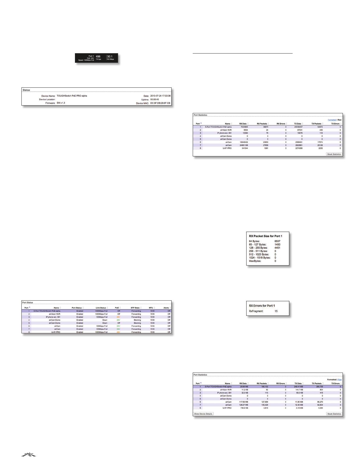
Place your mouse over a port to view its PoE status,
Speed setting, duplex mode, and statistics for TX and RX
throughput.
Status
Device Name Displays the customizable name or
identifier of the device. The Device Name (also known
as host name) is displayed in registration screens and
discovery tools.
Device Location Displays the description of the device’s
location.
Firmware Displays the firmware version of the
Configuration Interface.
Date Displays the current system date and time. The
date and time are displayed in YEAR-MONTH-DAY
HOURS:MINUTES:SECONDS format. The system date and
time is retrieved from the Internet using NTP (Network
Time Protocol). The NTP Client is disabled by default on the
Device tab. The device doesn’t have an internal clock, and
the date and time may be inaccurate if the NTP Client is
disabled or the device isn’t connected to the Internet.
Uptime This is the total time the device has been running
since the latest reboot (when the device was powered up)
or software upgrade. The time is displayed in days, hours,
minutes, and seconds.
Device MAC Displays the Media Access Control (MAC)
address of the device.
Port Status
Port Displays the number of the port.
Name Displays the name of the port.
Port Status Displays the activity status of the link
connection.
Link Status Displays the speed and duplex mode of the
port. If the port is inactive, “Down” is displayed.
PoE Displays the status and voltage of the PoE feature.
24V is displayed in green. 48V* is displayed in orange
(*available only on the TOUGHSwitch PoE PRO).
STP State Displays the Spanning Tree Protocol (STP)
state if STP is enabled on the Device tab. Displayed STP
states include Blocking, Learning, and Forwarding. (See
“Spanning Tree Protocol” on page 21 for more
information.)
MTU Displays the Maximum Transmission Unit (MTU),
which is the maximum packet size (in bytes) that a
network can transmit.
Alerts Displays whether alerts are set on this port.
Port Statistics
Raw/Formatted The statistics are available in two
formats. Click the format you prefer.
Raw Displays data in bytes. The Raw format is more
detailed because some bytes are not displayed when
formatted.
- RX/TX Packets For the 5-Port TOUGHSwitch PoE only,
you can hold your mouse over the statistic to display a
popup with packet size details.
- RX/TX Errors If there are errors, you can hold your
mouse over the statistic to display a popup with error
details.
Formatted Displays data in megabytes (MB), kilobytes
(kB), gigabytes (GB), or terabytes (TB) – up to three
decimal places. For example, if data is displayed in GB,
bytes are not counted until they reach a total of 1MB. If
1GB is displayed, the next number that will be displayed
is 1.001 GB (1 GB + 1 MB = 1.001 GB).
Port Displays the number of the port.
Name Displays the name of the port.
15
Chapter 4: Status TabTOUGHSwitch
PoE User Guide
Ubiquiti Networks, Inc.
RX Bytes/Data Displays the amount of data received.
RX Bytes displays the amount in the Raw format (actual
number of bytes). RX Data displays the amount in the
Formatted format – up to three decimal places in one of
these units of measurement: megabytes (MB), kilobytes
(kB), gigabytes (GB), or terabytes (TB).
RX Packets Displays the number of packets received
without errors.
RX Errors Displays the number of packets received with
errors.
TX Bytes/Data Displays the amount of data transmitted.
TX Bytes displays the amount in the Raw format (actual
number of bytes). TX Data displays the amount in
the Formatted format – up to three decimal places in
one of these units of measurement: megabytes (MB),
kilobytes(kB), gigabytes (GB), or terabytes (TB).
TX Packets Displays the number of packets transmitted
without errors.
TX Errors Displays the number of packets transmitted
with errors.
Reset Statistics Click this button to clear the displayed
statistics and reset them to zero.
Total Throughput
By default, Total Throughput and Data Distribution are
displayed.
Total Throughput displays the current data traffic on the
TOUGHSwitch in both graphical and numerical form. The
chart scale and throughput dimension (bps, kbps, Mbps)
change dynamically depending on the mean throughput
value. The statistics are updated automatically.
Data Distribution
Two pie charts, RX and TX, display the data traffic allocated
among the ports of the TOUGHSwitch. The pie charts are
updated automatically.
All/Last 20 sec By default, the pie charts are displayed in
All format, which is cumulative over time. To display data
distribution for the last 20 seconds, click Last 20 sec.
Details for Port
To display Packet Distribution, Packet Rate, and Throughput
for a specific port, click the port on the image. The
selected port is highlighted in blue.
To return to the default view displaying Total Throughput
and Data Distribution, click Show Device Details.
Packet Distribution
A pie chart, Packet Distribution, displays the current packet
sizes going through the port. The pie chart is updated
automatically.
Note: The TOUGHSwitch PoE PRO does not display
Packet Distribution.
All/Last 20 sec By default, the pie chart is displayed in All
format, which is cumulative over time. To display packet
distribution for the last 20 seconds, click Last 20sec.
16
Chapter 4: Status TabTOUGHSwitch
PoE User Guide
Ubiquiti Networks, Inc.
Packet Rate
Packet Rate displays the current packets per second rate
on the port in both graphical and numerical form. The
chart scale and packet rate dimension change dynamically
depending on the mean packet rate value. The statistics
are updated automatically.
Throughput
Throughput displays the current data traffic on the port
in both graphical and numerical form. The chart scale
and throughput dimension (bps, kbps, Mbps) change
dynamically depending on the mean throughput value.
The statistics are updated automatically.
17
Chapter 5: Device Tab TOUGHSwitch
PoE User Guide
Ubiquiti Networks, Inc.
Chapter 5: Device Tab
The Device tab allows you to configure and use the
Firmware Update, Management Network Settings, Basic
Settings, Management Connection Settings, Services,
Spanning Tree Protocol, Jumbo Frames, Device Discovery,
System Account, Device Maintenance, and Configuration
Management options for the TOUGHSwitch.
The TOUGHSwitch image displays the active LEDs and
connections. See “Hardware Overview” on page 1
for more information.
  • Page 1 1
  • Page 2 2
  • Page 3 3
  • Page 4 4
  • Page 5 5
  • Page 6 6
  • Page 7 7
  • Page 8 8
  • Page 9 9
  • Page 10 10
  • Page 11 11
  • Page 12 12
  • Page 13 13
  • Page 14 14
  • Page 15 15
  • Page 16 16
  • Page 17 17
  • Page 18 18
  • Page 19 19
  • Page 20 20
  • Page 21 21
  • Page 22 22
  • Page 23 23
  • Page 24 24
  • Page 25 25
  • Page 26 26
  • Page 27 27
  • Page 28 28
  • Page 29 29
  • Page 30 30
  • Page 31 31
  • Page 32 32
  • Page 33 33
  • Page 34 34
  • Page 35 35
  • Page 36 36
  • Page 37 37
  • Page 38 38
  • Page 39 39
  • Page 40 40
  • Page 41 41
  • Page 42 42
  • Page 43 43

Ubiquiti Networks TOUGH Switch PoE PRO TS-8-PRO User manual

Category
Networking
Type
User manual

Ask a question and I''ll find the answer in the document

Finding information in a document is now easier with AI