Huffy 214946C User manual
- Type
- User manual

1
05/03 P/N 214946C
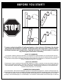
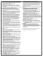
WARNING
FAILURE TO FOLLOW THESE WARNINGS MAY RESULT
IN SERIOUS INJURY AND/OR PROPERTY DAMAGE.
Owner must ensure that all players know and follow
these rules for safe operation of the system.
• DO NOT HANG on the rim or any part of the system
including backboard, support braces or net.
• During play, especially when performing dunk type
activities, keep player's face away from the backboard, rim
and net. Serious injury could occur if teeth/face come in
contact with backboard, rim or net.
• Do not slide, climb, shake or play on base and/or pole.
• After assembly is complete, fill system completely with
water or sand and stake to the ground. Never leave system
in an upright position without filling base with weight, as
system may tip over causing injuries.
• When adjusting height or moving system, keep hands and
fingers away from moving parts.
• Do not allow children to move or adjust system.
• During play, do not wear jewelry (rings, watches, necklaces,
etc.). Objects may entangle in net.
• Surface beneath the base must be smooth and free of
gravel or other sharp objects. Punctures cause leakage and
could cause system to tip over.
• Keep organic material away from pole base. Grass, litter,
etc. could cause corrosion and/or deterioration.
• Check pole system for signs of corrosion (rust, pitting,
chipping) and repaint with exterior enamel paint. If rust has
penetrated through the steel anywhere, replace pole
immediately.
• Check system before each use for proper ballast, loose
hardware, excessive wear and signs corrosion and repair
before use.
•
Check system before each use for instability.
• Do not use system during windy and/or severe weather
conditions; system may tip over. Place system in the
storage position and/or in an area protected from the wind
and free from personal property and/or overhead wires.
• Never play on damaged equipment.
• See instruction manual for proper installation and
maintenance.
• When moving system, use caution to keep mechanism from
shifting.
• Keep pole top covered with cap at all times.
• Do not allow water in tank to freeze. During sub-freezing
weather add non-toxic antifreeze, sand or empty tank
completely and store. (Do not use salt.)
• Use extreme caution if placing system on sloped surface.
System may tip over more easily.
201241 2/99
In the U.S.:1-800-558-5234 and Canada: 1-800-284-8339
Toll-Free Customer Service Number for U.S: 1-800-558-5234, For Canada: 1-800-284-8339, For Europe: 00 800 555 85234 (Sweden: 009 555 85234), For
Australia: 1-800-333 061 - Internet Address: http://www.huffysports.com
Most injuries are caused by misuse and/or not following instructions. Use caution
when using this system.
• If using a ladder during assembly, use extreme caution.
• Two (2) people are recommended for this operation.
• Check base regularly for leakage. Slow leaks could cause system to
tip over unexpectedly.
• Seat the pole sections properly (if applicable). Failure to do so could
allow the pole sections to separate during play and/or transport of the
system.
• Climate, corrosion or misuse could result in system failure.
• Minimum operational height is 6' 6" (1.98 m) to the bottom of
backboard.
• This equipment is intended for home recreational use only and NOT
excessive competitive play.
• Read and understand the warning label affixed to pole. Label is
shown on page 1.
• The life of your basketball pole depends on many conditions. The
climate, placement of the pole, the location of the pole, exposure to
corrosives such as pesticides, herbicides or salts are all important.
• If technical assistance is required, contact Huffy Sports.
• Adult supervision is recommended when adjusting height.
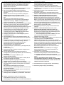
FAILURE TO FOLLOW THESE SAFETY INSTRUCTIONS MAY
RESULT IN SERIOUS INJURY, PROPERTY DAMAGE AND WILL
VOID WARRANTY.
Owner must ensure that all players know and
follow these rules for safe operation of the system.
To ensure safety, do not attempt to assemble this system without
following the instructions carefully. Proper and complete assembly,
use and supervision is essential for proper operation and to reduce
the risk of accident or injury. A high probability of serious injury
exists if this system is not installed, maintained, and operated
properly. Check entire box and inside all packing material for parts
and/or additional instructional material. Before beginning
assembly, read the instructions and identify parts using the
hardware identifier and parts list in this document.
For more information on assembly, placement, proper use and
maintenance, visit The American Basketball Council website at
http://www.smarthoops.com.
SAFETY INSTRUCTIONS
51
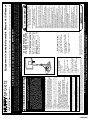
REQUIRED TOOLS AND
MATERIALS:
• Two People
• Tape Measure
• Wood Board (Scrap)
• Wrenches: (Two of Each) 7/16”,
1/2”, 9/16”, 3/4” or Large and
Small Adjustable Wrenches
• Sawhorse or Support Table
• Garden Hose or Sand (300 lb.)
(136 kg)
• Hammer
• Tape
• Phillips Screwdriver
• 1/2” & 9/16” Extended Deep
Socket w/ Extension
Recommended
© COPYRIGHT 2001 by HUFFY SPORTS
®
WRITE IN YOUR MODEL NUMBER:_________________
Customer Service Center • N53 W24700 South Corporate Circle • Sussex, WI 53089 • U.S.A.
A Huffy Company
Portable Basketball System with Elevator-Owners Manual
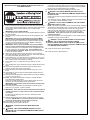
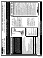
IMPORTANT!
In U.S. and Canada only:
Have questions?...don’t go back to the store!
We appreciate your purchasing one of our many fine products. We are sure that you will be very satisfied with your selection. Although great care and effort have been taken, occasionally problems may occur. To
ensure prompt and correct handling of any problems, or to answer any questions, please contact our Toll-Free Customer Service Number listed below. Service will be quicker if you have your Model Number
(found on carton) and assembly instructions ready when calling. PLEASE WRITE YOUR MODEL NUMBER IN THE SPACE PROVIDED ABOVE.
NOTICE TO ASSEMBLERS
ALL Huffy Sports basketball Systems,
including those used for DISPLAYS,
MUST be assembled and ballasted with
sand or water according to instructions.
Failure to follow instructions could result
in SERIOUS INJURY. It is NOT
acceptable to devise a makeshift weight
system.
The NBA and individual NBA member team identifications reproduced on this product are
trademarks and copyrighted designs, and/or other forms of intellectual property, that are the
exclusive property of NBA Properties, Inc. and the respective NBA member teams and may not
be used, in whole or in part, without the written consent of NBA Properties, Inc.
Page is loading ...

05/03 P/N 214946C
3
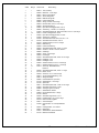
* You may have extra parts with this model.
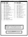
HARDWARE IDENTIFIER (BOLTS & SCREWS)
HARDWARE IDENTIFIER (NUTS & WASHERS)
Item #8 (1)
Item #16 (2)
Item #21 (2)
Item #18 (2)
Item #33 (1)
Item #45 (4)
Item #41 (1)
Item #29 (2)
Item #12 (1)
Item #26 (1)
Item #35 (5)
Item #30 (2)
Item #42 (1)
Item 47 (5)*
Item #17 (14)
Item #14 (2)
Item #10 (3)*
Item #34 (3)
Item #53 (2)
Item #13 (12)*

4
P/N 214946C 05/03
HARDWARE IDENTIFIER (STEEL SPACERS & RODS)
HARDWARE IDENTIFIER (PLASTIC SPACERS, CAPS & CLIPS)
Item #36 (1)
Item #39 (2)
Item #44 (4)
Item #55 (4)
Item #48 (1)
HARDWARE IDENTIFIER (OTHER)
Item #7 (1)
Item #31 (12)

05/03 P/N 214946C
5
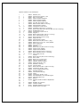
Item Qty. Part No. Description
1 1 206615 Tank, (Black)
2 1 200628 Wheel Axle, 11-3/4 Long
3 4 226401 Wheel, 4 “ (Black)
4 1 900007 Top Pole Section
5 1 908480 Middle Pole Section
6 1 900240 Bottom Pole Section
7 1 202820 Rod, 3/8 O.D. x 4-3/4 Long
8 1 206934 Eyebolt, 3/8-16 x 2 1/2 Long
9 1 206949 Pivot Bracket, Upper
10 3* 203063 Nylon Insert Lock Nut, 3/8-16
11 2 906206 Strut, 1” O.D. x 31-1/4 Long
12 1 201625 Bolt,Yellow Dichromate, 5/16-18 X 3.60" Long
13 12* 203218 Washer, Flat, 3/8 I.D.
14 2 203220 Nylon Insert Lock Nut, 5/16-18
15 1 201568 Anchor, T-Strap
16 2 203798 Bolt, Hex Flange, 5/16-18 x 1-1/2 Long
17 14 203100 Nut, Hex Flange, 5/16-18
18 2 203103 Carriage Bolt, 5/16-18 x 2 Long
19 1 900223 Wheel Bracket
20 1 206948 Pivot Bracket, Lower
21 2 206252 Bolt, Hex Head, 3/8-16 x 1 Long
22 1 206956 Disc, 5" O.D. x 13/32 I.D., Plastic
23 1 906606 Handle Bar
24 1 206940 Axle, 21" Long
25 2 206938 Push Cap
26 1 203330 Bolt, Hex Head, 3/8-16 x 4-1/2 Long
27 1 206604 Handle, Front, Plastic
28 1 206605 Handle, Back, Plastic
29 2 203038 Bolt, Carriage, 5/16-18 x 2-3/4 Long
30 2 203217 Carriage Bolt, 5/16-18 x 1-1/2 Long
Item
Qty. Part No. Description
31 12 201219 Smart Clip, Net Holder
32 1 Rim
33 1 206360 Bolt, Hex Head, 3/8-16 x 2.625 Long
34 3 201124 Nut, 3/8-16
35 5 206304 Bolt 1/2-13 x 6-5/16 Long
36 1 200516 Vinyl Bolt Cover, 5/16
37 1 202814 Cap, Pole Top
38 2 900846 Board Bracket, (Black)
39 2 201129 Spacer, 1-3/4 Long
40 1 201160 Pawl Lever
41 1 240017 Bolt, Hex Head, 1/4-20 x 2-1/4 Long
42 1 203493 Lock Nut, Hex Head 1/4-20
43 4 804808 Elevator Tube, (Black)
44 4 206311 Spacer, Plastic
45 4 204804 Screw, Phillips Head, 3/4 Long
46 1 201159 Ratchet
47 5* 206340 Lock Nut, Hex Head, 1/2-13
48 1 206305 Clevis Pin 1/4 x 2-9/32 Long
49 1 203124 Stake, Tie Down
50 2 203617 Plug Cap
51 1 201268 Label, Height Adjustment and Moving
52 1 Net
53 2 206303 Washer, 1/4 x 9/32 I.D.
54 1 200627 Wheel Carriage
55 4 201651 Spacer, Plastic, Wheel Axle
56 1 201125 Return Ratchet Spring
WARRANTY CARD:
Please remember to complete your product registration form either on-line at:
www.huffysports.com/warrantycard or mail-in the enclosed postcard.
WARNING: IF YOUR SYSTEM IS EQUIPPED WITH AN ACRYLIC BACKBOARD,
EXAMINE BACKBOARD FOR ANY DAMAGE THAT MAY HAVE OCCURRED
DURING SHIPMENT. CRACKS IN THE BACKBOARD COULD RESULT IN
SUDDEN BREAKAGE. IF BACKBOARD IS DAMAGED IN ANY WAY PRIOR TO OR
AFTER ASSEMBLY, CALL TOLL-FREE NUMBER FOR FREE REPLACEMENT:
U.S. 1-800-558-5234; CANADA: 1-800-284-8339; http://www.huffysports.com
PARTS LIST - See Hardware Identifier

6
P/N 214946C 05/03
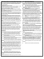
INSTRUCTIONS
IMPORTANT! WRITE MODEL NUMBER FROM BOX ONTO PAGE 1 OF
THIS OWNERS MANUAL
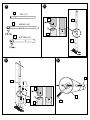
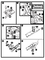
1. Remove all contents from underside of tank. Install wheel axle (2) through
wheel carriage (54) and install wheels (3) onto wheel axle (2) with spacers
(55) as shown. Secure wheel bracket as shown, a deep socket is
recommended.
IMPORTANT! DO NOT OVER TIGHTEN.
2. Correctly identify each pole section and mark indicated distance from ends
with tape as shown.
3. Align pole top and middle pole sections as shown using alignment mark
and hole.
IMPORTANT! Holes in top (4) and middle pole (5) sections MUST
align to correctly position elevator system toward playing surface.
Bounce pole top (4) and middle section (5) together as shown until they
no longer move toward taped reference mark. NOTE: Pole sections
should have a 3-1/2" (9 cm) minimum overlap.
4. IMPORTANT! Holes in top (4) and bottom pole (6) sections MUST
align to correctly position elevator system toward playing surface.
Add bottom pole section (6) to assembly as shown using alignment mark
and hole, and bounce until completely tight. Once assembled, pole
sections CAN NOT be separated! NOTE: Pole sections should have a
3-1/2" (9 cm) minimum overlap.
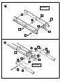
5. Install rod (7) through holes in bottom pole section (6) and eyebolt (8).
6. Insert pole assembly into tank assembly as shown. Secure pole assembly
with upper pivot bracket (9) and lock nut (10).
7. Secure base struts (11) to pole using bolt (12), washers (13), and nut (14),
as shown. Place vinyl bolt cover (36) over exposed bolt threads. Rotate
the non-secured ends of base struts (11) as shown.
8. Secure base struts (11) to base using bolt (16), washers (13), and
nut (17).
9. Insert carriage bolts (18) into middle set of holes on wheel bracket (19) as
shown.
10. Attach lower pivot bracket (20) to wheel bracket (19) using bolt (21),
washers (13), disc (22), and nut (10) as shown.
11. Attach handle bar (23) to wheel bracket assembly using nuts (17) as
shown.
12. Install wheels (3) onto axle (24) and wheel bracket assembly with push
caps (25) as shown.
13. Attach wheel bracket assembly to base assembly using bolt (26), washers
(13), and nut (10) as shown.
14. NOTE: Two people recommended for this step. Carefully reposition
entire assembly to upright position.
Attach front of plastic handle (27) to back of plastic handle (28) around
handle bar (23) using self-tapping screws (45) as shown.
IMPORTANT! Front of plastic handle (27) should face outward, away
from pole assembly.
15. Insert bolts (30) through plastic handle assembly, handle bar (23) and
attach nuts (17) as shown. Tighten completely.
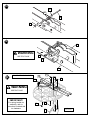
16. IMPORTANT! Test fit bolts into holes of backboard brackets (38) and
carefully rock them in a circular motion to ream out paint from holes
if necessary.
Fit spacer (39) into pawl (40). Then continue to assemble as shown.
Tighten completely.
17. Assemble elevator tubes (43) to ratchet components as shown. Tighten
completely. IMPORTANT! It is necessary for all parts to be installed
properly for this mechanism to work safely and properly.
18. Secure pawl (40) in place with clevis pin (48).
19. Stretch spring (56) into position with pliers.
WARNING: USE EYE PROTECTION WHEN INSTALLING
SPRINGS.
20. WARNING: TWO PERSON MINIMUM REQUIRED FOR THIS
PROCEDURE. NOT FOLLOWING RECOMMENDATION MAY RESULT
IN BODILY INJURY.
Starting with nuts (17) flush against backboard bracket (38), secure rim
and bracket to backboard. Bend upper halves of backboard brackets to
line up with holes in backboard and secure. Tighten completely. NOTE:
Mounting nuts and bolts supplied with rim hardware.
21. Assemble elevator tubes (43) to backboard bracket as shown.
22. WARNING: TWO PERSON MINIMUM REQUIRED FOR THIS
PROCEDURE. NOT FOLLOWING RECOMMENDATION MAY RESULT
IN BODILY INJURY.
Support pole on sawhorse. Attach backboard assembly to top pole section
(4) as shown.
Then install pole cap (37). NOTE: Two people are recommended for this
step, use caution, elevator assembly is heavy.
23. WARNING: DO NOT LEAVE ASSEMBLED UNIT UNATTENDED
WHEN EMPTY, MAY TIP OVER.
NOTE: Two people recommended for this procedure. Roll the completed
assembly to the desired playing area. Insert the T-strap (15) through the
slot on the back of the base as shown. Secure the unit to ground by
twisting the tie down stake (49) into the ground and hooking the T-strap
(15) onto the tie down stake (49). Fill tank with 33 gallons of water.
IMPORTANT! Add 2 gallons (7.6 liters) of non-toxic antifreeze in
sub-freezing climates.
24. Apply height adjustment and moving label (51) to front of pole as shown.
Regulation rim height is 10 feet (3.05 m).
WARNING: DO NOT ALLOW CHILDREN TO ADJUST HEIGHT.
WARNING: USE OF THIS PRODUCT WITHOUT PROPER
INSTALLATION OF SMART CLIPS, OR WHEN ALL SMART CLIPS
ARE NOT PRESENT COULD RESULT IN BODILY HARM. BE SURE TO
FOLLOW DIRECTIONS CAREFULLY.
25. Install net clips as shown. (See illustration)
26. Install net as shown. (See illustration)

05/03 P/N 214946C
7
IMPORTANT! WRITE MODEL NUMBER FROM BOX ONTO PAGE 1 OF THIS OWNERS MANUAL
1
1.
2
55
55
3
3
54
21
13
34
Page is loading ...

05/03 P/N 214946C
9
16
11
13
1
18
19
13
17
21
13
20
22
19
13
10
23
17
9
10
1
12
13
13
11
6
6
11
1
11
14
36
6
6. 7.
8.
9.
11.10.
SEE TEXT PAGE
WARNING
Page is loading ...

05/03 P/N 214946C
11
39
39
41
16.
IMPORTANT!
(See Text Page)
33
38
42
40
34
38
44
43
44
35
35
55
55
46
43
17.
IMPORTANT!
(See Text Page)
40
47
47

12
P/N 214946C 05/03
53
48
53
40
18.
43
38
56
43
19.
SEE TEXT PAGE
WARNING
38
29
32
17
Note
(See Text Page)
BOARD STYLE MAY VARY
SEE TEXT PAGE
WARNING
20.
IMPORTANT!
For spring loaded rim
assembly, refer to
instructions included with
rim hardware.
17
17
29

05/03 P/N 214946C
13
43
43
47
21.
37
4
43
43
SAWHORSE OR SUPPORT TABLE
22.
Note
(See Text Page)
35
35
47
47
35
44
44
SEE TEXT PAGE
WARNING
BOARD STYLE MAY VARY

14
P/N 214946C 05/03
50
15
23.
24.
IMPORTANT!
SEE TEXT PAGE
49
SEE TEXT PAGE
WARNING
Peel protective film from
surface of acrylic
backboard prior to use.
NOTE:
51
10 feet
(3.05 m)

05/03 P/N 214946C
15
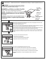
WARNING:
Use of this product without proper installation
of net clips, or when all net clips are not present could result in
bodily harm. Be sure to follow directions carefully.
AVERTISSEMENT : L'utilisation de ce produit sans installer
correctement ou toutes les pinces du filet risque de causer des
blessures. Veillez à suivre scrupuleusement les instructions.
WARNUNG: Ein Gebrauch dieses Produkts ohne ordnungsgemäß
angebrachte Netzhalteklammern bzw. ohne den Gebrauch der
Netzhalteklammern kann Verletzungen nach sich ziehen. Die Anleitung
genau befolgen.
ADVERTENCIA: Si este producto se usa con los sujetadores de la red
incorrectamente instalados, o si no están todos presentes, se pueden
ocasionar lesiones corporales. Asegúrese de seguir cuidadosamente
las instrucciones.
Install net clips. Installez les pinces du filet. Netzhalteklammern anbringen. Instale los sujetadores de la red.
CLIP “ARM”
" BRAS " DE LA
PINCE
CLIP-ARM
"BRAZO" DEL
SUJETADOR
CLIP “BODY”
" CORPS " DE LA PINCE
CLIP-HAUPTTEIL
"CUERPO" DEL
SUJETADOR
Insert one “arm” of clip (19) into ram (18) as shown. Twist “body” of clip slightly so that second “arm”
slides over the top of the first “arm” as shown.
Push in direction indicated by arrows.
Insérez un " bras " de la pince (19) dans l'éperon (18), comme illustré. Tournez légèrement le corps de la
pince de sorte que le second bras glisse par-dessus le premier, comme illustré.
Einen Arm des Clips (19) wie gezeigt in die Spirale (18) einsetzen. Den Hauptteil des Clips etwas drehen,
sodass der zweite Arm wie gezeigt oben über den ersten Arm geschoben werden kann.
Introduzca un "brazo" del sujetador (19) en el accionador (18) como se muestra. Tuerza ligeramente el
"cuerpo" del sujetador de manera que el segundo "brazo" se deslice sobre el primer "brazo" como se
muestra.
Push second “arm” back and into ram as shown.
Poussez dans le sens des flèches.
In die durch die Pfeile angezeigte Richtung schieben.
Empuje hacia la dirección que indican las flechas.
Twist “body” of clip slightly again to spread “arms” of clip.
Clip “arms” must be flat and touching edge to edge as shown, not overlapping.
Tournez légèrement le corps de la pince une nouvelle fois pour en étaler les bras.
Den Hauptteil des Clips noch einmal leicht drehen, um die Arme des Clips zu spreizen.
Otra vez tuerza ligeramente el "cuerpo" del sujetador para abrir los "brazos" del
sujetador.
AA
BB
CC
25.
32
31

16
P/N 214946C 05/03
Install net.
Installez le filet.
Das Netz anbringen
Instale la red.
Insert net into bottom of clip as shown.
Insérez le filet dans la base de la pince, comme illustré.
Das Netz wie gezeigt unten in den Clip stecken.
Introduzca la red en la parte inferior del sujetador como se muestra.
SIDE VIEW
VUE DE CÔTÉ
SEITENANSICHT
VISTA LATERAL
Twist net until it snaps into position.
Net must be centered through clip.
Tournez le filet jusqu'à ce qu'il s'enclenche en position.
Das Netz drehen, bis es einschnappt.
Tuerza la red hasta que quede conectada en su posición.
Le filet doit être centré dans la pince.
Das Netz muss im Clip zentriert werden.
La red debe quedar centrada a través del sujetador.
NET
FILET
NETZ
RED
NETCLIP
PINCE DE FILET
NETZHALTEKLAMMER
SUJETADOR DE LA RED
26.
32
31
32
SIDE VIEW
VUE DE CÔTÉ
SEITENANSICHT
VISTA LATERAL
NET
FILET
NETZ
RED
NETCLIP
PINCE DE FILET
NETZHALTEKLAMMER
SUJETADOR DE LA RED
Page is loading ...
Page is loading ...
Page is loading ...
Page is loading ...
Page is loading ...
Page is loading ...
Page is loading ...
Page is loading ...
Page is loading ...
-
 1
1
-
 2
2
-
 3
3
-
 4
4
-
 5
5
-
 6
6
-
 7
7
-
 8
8
-
 9
9
-
 10
10
-
 11
11
-
 12
12
-
 13
13
-
 14
14
-
 15
15
-
 16
16
-
 17
17
-
 18
18
-
 19
19
-
 20
20
-
 21
21
-
 22
22
-
 23
23
-
 24
24
-
 25
25


Huffy 214946C User manual
- Type
- User manual
Ask a question and I''ll find the answer in the document
Finding information in a document is now easier with AI
in other languages
- français: Huffy 214946C Manuel utilisateur
- español: Huffy 214946C Manual de usuario
- Deutsch: Huffy 214946C Benutzerhandbuch
Related papers
-
Huffy 15 User manual
-
-
-
-
-
-
-
-
-
Other documents
-
Spalding 214949B User manual
-
-
-
-
-
-
-
-
-
 Boston Loft Furnishings ATG3118 Installation guide
